Australian
National
University
Developing techniques for high fidelity studies
of reactions with light weakly bound nuclei
A thesis submitted for the degree of
Doctor of Philosophy
of The Australian National University
c
by Ian Paul Carter
What they undertook to do
They brought to pass;
All things hang like a drop of dew
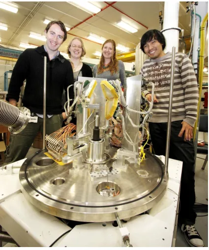
This thesis describes the final stages in the development of the radioactive ion beam capability at the Australian National University. A large part of this thesis was devoted to the development, testing and implementation of a tracking detector system; a critical component of this capability. From these advancements, the first RIB measurements at the ANU were executed using beams of 8Li. In addition, parallel to this developmental work, reactions with the stable but weakly-bound 9Be nucleus were carried out. This thesis describes the experimental setup, measurement, analysis and interpretation of measurements made to understand breakup in reactions of9Be with nuclei ranging from 40Ca to 124Sn at near and below-barrier energies. All experiments were carried out using the 14UD tandem electrostatic accelerator of the Heavy Ion Accelerator Facility at the ANU. All measurements documented in this work were made with the assistance of the nuclear reaction dynamics research group and the technical staff. This project was originally motivated by Prof. Mahananda Dasgupta and Prof. David Hinde. The radioactive ion beam experiments were carried out using the RIB capability integrated with a large-area high-resolution silicon detector array, which was also used for the 9Be breakup measurements. In designing the RIB tracking system, the author utilised advice and assistance from Prof. Mahananda Dasgupta, Prof. David Hinde, Dr Ramachandran, Mr Alistair Muirhead, Mr Dimitrios Tsifakis and Mr Steve Marshall. In the development of the RIB capability, the author also acknowledges the contributions of the Research School of Physics and Engineering Mechanical Workshop and Tom Rhymes Electronic Workshop. The author worked closely with fellow colleagues Ms Kaitlin Cook, Dr Huy Luong, and Dr Sunil Kalkal in the extraction of the breakup events from the array. All data analysis was done by the author using customised scripts written by Dr Huy Luong based on the existing C++ ROOT framework.
international conferences, and work published in peer reviewed journals:
1. Recent developments of SOLEROO: Australia’s First high Energy Radioactive Ion Beam Capability,
I.P. Carter, M. Dasgupta, D.J. Hinde, D.H. Luong, E. Williams, K. Ra-machandran, K.J. Cook, A.G. Muirhead, S. Marshall and T. Tunningley, EPJ Web of Conf. 91, 00001 (2015).
2. An Ion Beam Tracking System based on a Parallel Plate Avalanche Counter,
I.P. Carter, K. Ramachandran, M. Dasgupta, D.J. Hinde, R. Rafiei, D.H. Luong, E. Williams, K.J. Cook, S. McNeil, D.C. Rafferty, A.B. Harding, A.G. Muirhead and T.Tunningley, EPJ Web of Conf. 63, 02022 (2013).
3. Determination of the angular distribution of evaporation residues following transmission through the superconducting solenoidal separator SOLITAIRE,
I.P. Carter, M.L. Brown, M. Dasgupta, D.J. Hinde, M. Evers, D.H. Luong, A. Wakhle and E. Williams, EPJ Web of Conf. 35, 05003 (2012).
The author was closely involved with the following works, which are directly related to the work on breakup in this thesis:
4. Disintegration locations in 7Li → 8Be transfer-triggered breakup at near-barrier energies,
E.C. Simpson, K.J. Cook, D.H. Loung, Sunil Kalkal,I.P. Carter, M. Dasgupta, D.J. Hinde and E. Williams, Phys. Rev. C93, 024605 (2016).
5. Asymptotic and near-target direct breakup of 6Li and 7Li,
Sunil Kalkal, E.C. Simpson, D.H. Loung, K.J. Cook, M. Dasgupta, D.J. Hinde,
namics,
M. Dasgupta, E.C. Simpson, D.H. Luong, Sunil Kalkal, K.J. Cook, I. P. Carter, D.J. Hinde and E. Williams, EPJ Web of Conf. 117, 08005 (2016).
7. Breakup following interactions with light targets: Investigating new methods to probe nuclear physics input to the cosmological lithium problem,
K.J. Cook, D.H. Luong, I.P Carter, M. Dasgupta, D.J. Hinde, S. McNeil, D. Rafferty, K. Ramachandran, C. Simenel and E. Williams, EPJ Web of Conf.
91, 00002 (2015).
8. Breakup mechanisms for 7Li + 197Au, 204Pb systems at sub-barrier energies, D.H. Luong, M. Dasgupta, D.J. Hinde, R. du Rietz, R. Rafiei, M. Evers, C.J. Lin, A. Wakhle, K. Ramachandran, I.P. Carterand A. Diaz-Torres, EPJ Web of Conf. 63, 02004 (2013).
9. Developing new methods to investigate nuclear physics input to the cosmological lithium problem,
K.J. Cook, D.H. Luong, E. Williams, I.P. Carter, M. Dasgupta, D.J. Hinde and K. Ramachandran, EPJ Web of Conf. 63, 03011 (2013).
10. Nuclear Reaction Dynamics Research at the Australian National University, D. J. Hinde, M. Dasgupta, I.P. Carter, K.J. Cook, M. Evers, D.H. Luong, K. Ramachandran, D. Rafferty, C. Simenel, A. Wakhle and E. Williams, EPJ Web of Conf. 63, 02005 (2013).
11. Applications of a 6.5T Superconducting Solenoidal Separator,
D.J. Hinde, M. Dasgupta, M.D. Rodriguez, R. Rafiei, M.L. Brown, A.J. Horsley,
have been or will be published:
12. Examining the role of transfer coupling in sub-barrier fusion of 46,50Ti + 124Sn, J. F. Liang, J. M. Allmond, C. J. Gross, P. E. Mueller, D. Shapira, R. L. Varner, M. Dasgupta, D. J. Hinde, C. Simenel, E. Williams, K. Vo-Phuoc, M. L. Brown, I. P. Carter, M. Evers, D. H. Luong, T. Ebadi, and A. Wakhle, Phys. Rev. C94, 024616 (2016).
13. Multinucleon transfer in 16,18O, 19F + 208Pb reactions at energies near the fusion barrier,
D. C. Rafferty, M. Dasgupta, D. J. Hinde, C. Simenel, E. C. Simpson, E. Williams, I. P. Carter, K. J. Cook, D. H. Luong, S. D. McNeil, K. Ramachan-dran, K. Vo-Phuoc, and A. Wakhle, Phys. Rev. C94, 024607 (2016).
14. Exploring dissipative processes at high angular momentum in 58Ni+60Ni reac-tion,
E. Williams, D.J. Hinde, M. Dasgupta, I.P. Carter, K.J. Cook, D.Y. Jeung, D.H. Luong, S.D. McNeil, C.S. Palshetkar, D.C. Rafferty, K. Ramachandran, C. Simenel, E.C. Simpson and A. Wakhle, EPJ Web of Conf. 117, 08021 (2016).
15. Systematic study of quasifission characteristics and timescales in heavy element formation reactions,
D.J. Hinde, E. Williams, G. Mohanto, C. Simenel, M. Dasgupta, A. Wakhle,
I.P. Carter, K.J. Cook, D.Y. Jeung, D.H. Luong, C.S. Palshetkar, E. Prasad, D.C. Rafferty, R. du Rietz and E.C. Simpson, EPJ Web of Conf. 117, 08006 (2016).
16. Experimental study of the quasifission, fusion-fission, and de-excitation of Cf compound nuclei,
elements,
K. Hammerton, Z. Kohley, D.J. Hinde, M. Dasgupta, A. Wakhle, E. Williams, V.E. Oberacker, A.S. Umar, I.P. Carter, K.J. Cook, J. Greene, D.Y. Jeung, D.H. Luong, S.D. McNeil, C.S. Palshetkar, D.C. Rafferty, C. Simenel, and K. Stiefelv, Phys. Rev. C91, 041602 (2015).
18. Observation of mass-asymmetric fission of mercury nuclei in heavy ion fusion, E. Prasad, D.J. Hinde, K. Ramachandran, E. Williams, M. Dasgupta, I.P. Carter, K.J. Cook, D. Y. Jeung, D. H. Luong, S. McNeil, C. S. Palshetkar, D. C. Rafferty, C. Simenel, A. Wakhle, J. Khuyagbaatar, Ch. E. D¨ullmann, B. Lommel, and B. Kindler, Phys. Rev. C91, 064605 (2015).
19. How signatures of quasifission evolve in reactions forming Curium,
E. Williams, D.J. Hinde, M. Dasgupta, R. du Rietz, I.P. Carter, M. Evers, D.H. Luong, S.D. McNeil, D. C. Rafferty, K. Ramachandran and A. Wakhle, EPJ Web of Conf. 86, 00063 (2015).
20. Investigating energy dissipation through nucleon transfer reactions,
D.C. Rafferty, M. Dasgupta, D.J. Hinde, C. Simenel, K.J. Cook, I.P. Carter, D.H. Luong, S.D. McNeil, K. Ramachandran, A. Wakhle and E. Williams, EPJ Web of Conf. 91, 00010 (2015).
21. Evolution of signatures of quasifission in reactions forming curium,
E. Williams, D. J. Hinde, M. Dasgupta, R. du Rietz,I.P. Carter, M. Evers, D.H. Luong, S.D. McNeil, D.C. Rafferty, K. Ramachandran, and A. Wakhle, Phys. Rev. C88, 034611 (2013).
22. Study of fusion reactions forming Cf nuclei,
K. Ramachandran, D.J. Hinde, M. Dasgupta, E. Williams, A. Wakhle, D.H. Luong, M. Evers,I.P. Carterand S. Das, EPJ Web of Conf. 63, 02017 (2013).
The material in this thesis is, to the best of my knowledge, original and has not been submitted in whole or part for a degree at any other university.
Ian P. Carter
faster !.
Arnold Schwarzenegger
Acknowledgements
I would like to express my special appreciation and thanks to Nanda Dasgupta and David Hinde, you both have been tremendous mentors to me. I would like to thank you for believing in me, for your guidance, encouraging my research and for allowing me to grow as a research scientist. The skills and qualities I have picked up from you two will stay with me in my daily life long after I have finished my PhD. Your advice on both research as well as on my career has been priceless. You encouraged me to not only grow as a physicist but also as an independent thinker. Thank you for your support, patience and for having me on your team. I want to express my thanks to Alistair Muirhead, for his immense contribution to the technical challenges of my project and his ‘we could do better’ attitude. He was always ready on hand to help out in an instance and offer his expert knowledge of precision engineering. Seeing how conceptual ‘one of a kind’ ideas, usually drawn on the ‘back of an envelope’ by David or Nanda, come to life with Alistair’s creativity has both been inspiring and exciting.
I would like to thank Ramachandran for his help at the beginning of my PhD with the development of the tracking detectors when I really thought it was going over my head. His calm nature and patience helped to drive the project forward. I would like to say special thanks to Duc Huy Luong for his invaluable expertise on all things ’root’ related, and for his help/pain caused in troubleshooting codes. I am very grateful for the support I received from Kaitlin Cook, practically right up to the final days of this PhD thesis. Even though she was herself stresses as she is writing up her thesis. She was advising on breakup analysis, coding and read
my beam-time and for reading draft chapters of this thesis, along with Joe Walshe, Sunil Kalkal, Matthew Reed and Edward Simpson. Thank you all for your support, particularly when I was writing and encouraging me to strive towards my goal. To Edward Simpson in particular, thanks heaps for the pep talks. I really appreciate you taking the time to read the final draft of this entire thesis.
I want to thank the entire reaction dynamics group. Without our collective efforts as a team, projects like mine could not go ahead. You guys really put in the effort for the radioactive beam experiments. For those who were on night shifts, big thumbs up. To Sunil for her enlightening sarcasm, to Prasad for his impudent comments. To Cedric for our night shift beers and music. To Yun, I think you’re tiny but dangerous. To Dominic for having the best, ‘I don’t want to give a three-minute talk’ excuse. To Chandrima, for your never tiring questions. To Jess, for your newly found accelerator glory. To Kirsten, for your ‘granny-like’ attitude, and for helping me through the last few months of my thesis writing.
Thanks to our technical officers Dimitrios Tsifakis, Thomas Tunningley, Alan Cooper, Peter Linardakis, John Bockwinkel, Justin Heighway, Lariosa Lorenzo and the accelerator operations manager Nikolai Lobanov. Your creative minds and capable hands have made an enormous contribution. Thanks to Petra Rickman, just for being awesome.
Research capabilities in nuclear physics have greatly expanded in recent years with the availability of radioactive ion beams and exotic nuclei near the drip line. As a result, new phenomena are being discovered in areas of nuclear reactions and nuclear structure. This thesis work is focused on studies of reaction mechanisms of light weakly bound nuclei at energies near the Coulomb barrier, where nuclear structure influences nuclear reactions outcomes. Two strands towards this end were followed concurrently; the first, to develop a radioactive beam capability to enable reaction studies with6He and8Li nuclei, and the second, to study the systematics of breakup mechanisms of the stable but weakly bound nucleus 9Be in interactions with targets of mass A = 40-124.
The radioactive beam capability at the Australian National University uses in-flight transfer reactions to produce light unstable beams. The radioactive ion species of interest are then transported and focused onto a secondary target using the magnetic field generated by a superconducting solenoid. The relatively low purities of the unstable beam obtained using a single solenoid (typically 30%) normally necessitates the use of two solenoids in tandem to further purify the radioactive ion beam as done at the TwinSol (USA) and RIBRAS (BRAZIL) facilities. A unique feature of the Australian National University (ANU) radioactive beam capability is a pair of tracking detectors placed at the exit of the solenoid that allows identification and determination of the trajectories of the radioactive species, and electronic tagging event-by-event. These detectors were developed and successfully implemented as part of this thesis work. The reconstruction of ion trajectories using these detectors aids in rejection of contaminant species. Effective beam purities of greater than 90%
have been achieved for 6He and8Li, with most impurities being tritons. The tracking detectors have demonstrated rate handling capability of 3×10⁶ particles per second.
and the angle of incidence of the ion on the secondary target, allowing precise reconstruction of reaction kinematics which is necessary for high fidelity studies of nuclear reactions. Details of the ion transport, tracking detector performance and secondary beam characteristics are described in this thesis, along with the results of the first experiment using a radioactive beam of 8Li from the ANU capability.
1 Getting to the Heart of Visible Matter 1
1.1 The Internuclear Potential . . . 4
1.2 Basic Reaction Outcomes . . . 6
1.3 Coupled Channels Model of Nuclear Reactions . . . 8
1.4 Reactions of Weakly-bound Nuclei . . . 9
1.4.1 Suppression of Complete Fusion . . . 10
1.4.2 Relationship Between Breakup and Fusion Suppression . . . . 11
1.4.3 The Need to Develop a Classical Trajectory Model . . . 13
1.5 Thesis Outline . . . 14
2 9Be Breakup Measurements 17 2.1 Production of Accelerated 9Be beams . . . 18
2.1.1 Negative Ion Source . . . 19
2.1.2 14UD Accelerated Beams . . . 20
2.2 Experimental Setup . . . 23
2.2.1 Targets and Beam Energies . . . 23
2.2.2 Detector Configuration . . . 26
2.2.3 Signal Processing . . . 28
2.2.4 DSSD Signals to Preamplification . . . 28
2.2.5 Preamplification to Amplification . . . 30
2.2.6 DAQ Trigger Condition . . . 30
2.3 Breakup Analysis . . . 31
2.3.1 Analysis of Raw Data . . . 31
2.3.2 Selecting True Breakup Events . . . 33
2.4 Derived Energy Variables . . . 36
2.5 Identification of Breakup Modes . . . 39
2.6 Determining Near-Target Breakup from Asymptotic Breakup . . . 43
2.7 Determination of Absolute Breakup Probabilities . . . 47
2.7.1 Normalisation to Rutherford Scattering . . . 47
2.7.3 Geometric Coincidence Efficiency Correction . . . 50
2.7.4 Simulation of Events where θ12 is Outside Coverage of Detector 50 2.7.5 Near-Target Breakup Probabilities . . . 52
2.8 Experimental Breakup Functions . . . 52
2.9 Summary . . . 56
3 Radioactive Ion Beams at the Australian National University 59 3.1 Methods of RIB Production . . . 61
3.1.1 The ISOL Approach . . . 62
3.1.2 In-Flight Approaches . . . 62
3.1.3 Q-Window in Transfer Reactions . . . 63
3.2 Principle of Operation of the ANU RIB Solenoidal Separator . . . 65
3.2.1 Superconducting Solenoidal Separator . . . 67
3.2.2 Focusing of Ion Beams Through a Solenoid . . . 68
3.3 Production of RIBs . . . 70
3.3.1 Beam Purity using a Single Solenoid Separator . . . 71
3.3.2 Origin of Beam Impurities . . . 75
3.3.3 7Li Energy Degraded Primary Beam . . . 75
3.3.4 Details of the RIBs Currently Optimised for SOLEROO . . . 78
3.4 Need for Tracking Detectors . . . 80
4 Development of Tracking Detectors for Tagging Radioactive Ion Beams 81 4.1 Requirements of a Tracking System . . . 81
4.2 Principles of Operation of Parallel Plate Avalanche Counters . . . 82
4.2.1 Design and Construction . . . 84
4.2.2 PPAC Design Improvements. . . 86
4.2.3 Signal Processing . . . 87
4.3 Performance of the Second-generation PPAC . . . 90
4.3.1 Pulse Height . . . 90
4.3.3 Position Response . . . 93
4.3.4 Correcting for Non-Linearity . . . 97
4.3.5 Efficiency of Event Detection . . . 100
4.3.6 Radiation Hardness . . . 107
4.4 Summary and Future Changes . . . 112
5 Experience of Using Tracking Detectors to Tag RIBs 117 5.1 SOLEROO Pilot Experiment . . . 117
5.1.1 Signal Processing and Data Acquisition . . . 118
5.2 Tagging and Purifying the RIB . . . 119
5.2.1 Tagging by (PPAC-1 - PPAC-2) ToF and∆E . . . 121
5.2.2 Using Longer Flight Paths . . . 122
5.2.3 Additional Selection Techniques . . . 124
5.3 Tracking to Further Characterise the RIB . . . 126
5.3.1 Tracking the Trajectories . . . 129
5.4 Combining Tagging and Tracking with BALiN . . . 134
5.4.1 Neutron Induced Reactions . . . 134
5.4.2 Tagging and Tracking for Reaction Kinematics . . . 136
5.5 Summary . . . 137
6 Experiments with 8Li beams 141 6.1 Interest in Reactions with 8Li . . . 141
6.1.1 Factors Affecting Fusion . . . 142
6.2 Measurement of Elastic Scattering . . . 143
6.2.1 RIB Energy . . . 144
6.2.2 Geometric Efficiency . . . 146
6.2.3 BALiN Energy vs. Reconstructed Angle . . . 148
6.2.4 Elastic Cross-Sections . . . 153
6.3 Measurement of Breakup . . . 155
6.3.1 Breakup Coincidence Measurements of Charged Particles . . . 155
6.4 Summary . . . 159
7.1 Breakup Mechanisms of Be . . . 161 7.2 Advancements in Radioactive Ion Beam Capability at the ANU . . . 163 7.3 First RIB Measurement . . . 164
A A Classical Trajectory Model 1
B 1st Generation PPAC Performance 3
C 8Li + 209Bi Reaction Modes 13
Bibliography 38
and joy that the natural order of things brings to the true scientist.
Lise Meitner (1878-1968)
1
Getting to the Heart of Visible Matter
Human curiosity has led us to question the nature of matter for thousands of years. The earliest known records go as far back to ancient Greece. In about 600 B.C.E, Thales, a pre-Socratic Greek philosopher from Miletus, discussed the microstructure of the world. He discovered that a piece of amber, when rubbed with fur, attracted hair and feather, suggesting that this perplexing force came from the amber. Thales was describing what we now call static electricity. However, he did not connect this force with any particle [1]. Not until around 460 B.C.E did another pre-Socratic Greek philosopher, Democritus, conceive the concept of the atom. He asked a question similar to this: "If you break a piece of matter in half, and then break it in half again, how many breaks will you have to make before you can break it no further?" At the end of this process, Democritus thought he would have the smallest possible bit of matter. He called these basic matter particles ‘atoms’, with the ancient Greek meaning being ‘indivisible’ [2]. Nevertheless, his concepts were still far from the modern model of the atom.
These ideas did not develop until 2000 years later, when in the 1800s John Dalton performed experiments with a variety of chemicals that showed that matter consisted of lumpy elementary particles (atoms) [3, 4]. Though he did not know the structure of these atoms, he was aware that his findings pointed to something fundamental, which lead to the formulation of Daltons Atomic Theory. In 1897, J.J. Thomson
discovered the electron that resulted in the proposed model for the structure of the atom, called the ‘plum pudding’ model [5]. Thomson thought of the atom as a uniform, positively charged sphere of matter in which contained embedded electrons, analogous to raisins in a cake.
In the years following, Thomson proposed a model of the structure of the atom. The pursuit of the nature of these fundamental building blocks of matter was still ongoing. Researchers attempted to test Thomson’s proposed structure for the atom. To assess the ‘plum pudding model’, in 1911, Ernest Rutherford bombarded a gold foil with α-particles emitted from a Radium source. Alpha particles, being much heavier than electrons, were expected to come out of the foil with their trajectories almost unaffected. Instead, a fewα-particles were found to be scattered through large angles, with some scattered by 180◦. This disagreement led to the formulation of the Rutherford model of the atom, in which the atom had a minuscule, dense nucleus containing most of its mass and charge [6–8]. In 1932 James Chadwick discovered the final constituent of atoms, a neutral particle with about the same mass as the proton, now called the neutron [9]. Models of the atomic nucleus consisting of protons and neutrons were quickly developed soon afterwards by Werner Heisenberg, Dmitri Ivanenko and others [10–14].
Since this time, much progress has been made in understanding the structure of the nucleus, and the fundamentals of the strong force that binds the neutrons and protons in the nucleus. Many of these advances have occurred by using accelerated beams of stable nuclei. More recently, Tanihata et al. [15] opened up a new avenue for exploring nuclear structure, through his pioneering experiments on nuclei outside the valley of stability. Their experimental measurements showed that nuclei such as 6He, 11Be, 11Li and 14Be have large interaction radii when compared to those of stable nuclei. Due to this extended matter radius, nuclei such as 6He and 11Li are now known as ‘halo nuclei’.
a part of this thesis, a radioactive beam capability called SOLEROO (SOLenoidal Exotic Rare isOtOpe separator [16, 17]) was made fully operational at the Australian National University (ANU), and the first experiments performed with radioactive ion beams at ANU were carried out. SOLEROO focuses towards the production and separation of light radioactive beams, which show some of the most unusual features of unstable nuclei. This thesis uses both stable beams of 9Be and volatile beams of 8Li to investigate major reaction outcomes (breakup and fusion) at energies near the fusion barrier. This work is carried out with the ultimate aim of providing inputs to the development of quantitative models that can predict outcomes of reactions involving weakly-bound nuclei.
Further, light nuclei such as 6,7Li and 9Be play a crucial role in the chemical evolution of the universe [18–24]. As such, understanding the reaction outcomes after collisions of 9Be provides useful input into nuclear astrophysics. Near the fusion barrier, light weakly-bound nuclei such as 9Be have been found to break up into their cluster partitions, as initially suspected in Ref [25]. However, breakup of the projectile-like nucleus proceeds predominantly by the initial transfer of one or two nucleons [26, 27]. The aim of this thesis work is to investigate the different breakup mechanisms of 9Be and more exotic neutron-rich, unstable, weakly-bound nuclei. An understanding of these processes is crucial in elucidating the influence of their low threshold against breakup into cluster fragments on other reaction outcomes, particularly in nuclear collisions concerning fusion. In nuclear reactions with weakly-bound nuclei, breakup has been found to have a large contribution to suppression of fusion at above barrier energies [26–28].
r
V
(r
)
+
V
(r
)
+
V
(r
)
N
C
l
b
V
l
=0
l
> 0
b
[image:24.595.60.482.79.389.2]R
Figure 1.1: The sum of the Woods-Saxon nuclear, Coulomb, and centrifugal
potentials gives a series of potentials that depend on l. Rb and Vb are the
barrier radius and barrier energy respectively for a head-on collision. Illustration adapted from Ref [29].
1.1
The Internuclear Potential
on.
In describing nuclear collisions, due to the strong interactions between many nucleons in the colliding nuclei, a microscopic description of collisions is not usually performed. The interaction between two colliding nuclei is commonly described using a phenomenological potential that is constructed to account for many body interactions between nucleons. This internuclear potential can be broken into three physically relevant components: The potential arising from the strong nuclear interaction VN(r), the potential due to the Coulomb interaction, VC(r), and the centrifugal potential,Vl(r). The total internuclear potential is to first order given by:
where r is the centre-to-centre separation of the colliding nuclei. Usually, VN(r) is taken to be a Woods-Saxon nucleus-nucleus potential and is expressed by:
VN(r) = Vo
1 + expr−Ro
ao
, (1.2)
where Vo is the potential depth, ao is the surface diffuseness and:
Ro =ro(A
1 3
1 +A
1 3
2). (1.3)
Here ro is the nuclear radius parameter (typically 1.2 fm), and A1 and A2 are the mass number of the colliding nuclei [30]. These parameters are often extracted from fits of elastic scattering angular distributions using optical model calculations [31, 32].
The repulsive Coulomb potential term VC(r) between a point-like particle and a charged sphere of radius Ro fm, can be expressed as:
VC(r) =
Z1Z2e2
r For r >0 Z1Z2e2
r 3R2
o−r2
R3
o For r 60,
(1.4)
where e2 = 1.44 MeVfm and Z1,2 are the atomic numbers of the participants. The centrifugal potential Vl(r) from Eqn (1.2) is given by:
Vl(r) =
l(l+ 1)~2
2µr2 , (1.5)
wherel is the orbital angular momentum quantum number andµis the reduced mass. Figure (1.1) shows the resulting potentials for different values of angular momentum. It is the sum of the nuclear, Coulomb and centrifugal terms. Due to the centrifugal term, Eqn (1.1) results in a series of potentials that depend on l.
Eventually the local potential minimum, or ‘pocket’, disappears for some maximum value of l. At this point the capture of nuclei becomes impossible. As can be seen from thel dependence of the internuclear potential, the outcome of any particular collision depends on how close nuclei get to each other.
1.2
Basic Reaction Outcomes
The outcomes of any nuclear collision depend primarily on how close the two colliding nuclei get to each other. The distance of closest approach is parametrised by the impact parameterb, defined as
b= l
µυ, (1.6)
where l is the orbital angular momentum in the collision, µ is the reduced mass and υ is the asymptotic relative velocity of the two nuclei. The types of interactions between the nuclei are dependent on l, as shown in figure (1.2), since l defines the distance of closest approach of two nuclei Rmin. In this classical picture, reaction outcomes between two nuclei can be roughly classified into four categories [33], described below.
(i) Distant Collisions
Distant collisions are those with large impact parameters. Here, the Coulomb field determines the trajectories of these collisions, and the key resulting process is elastic scattering. The change in the Coulomb field can also cause excitations of low-lying states in both projectile and target, which is know as Coulomb excitation.
(ii) Grazing Collisions
Figure 1.2: Basic picture of nuclear collisions showing the outcome of a
nuclear reaction depends onl and thereforeb. Ri denotes the radius of nucleus
iand R is the sum of the radii of the colliding nuclei. Illustration adapted
from Ref [29]
are sufficiently close to allow nuclear interactions to occur, resulting in nucleon transfer, as well as inelastic scattering. These types of collisions are significant in this work.
(iii) Deep Inelastic Collisions
A peripheral collision occurs when the projectile’s orbit has an impact parameter less thanbgr, resulting in significant matter overlap. Examples of such collisions are deep inelastic collisions, where a substantial fraction of the relative kinetic energy gets dissipated into internal excitations of the projectile and target-like nuclei. Here the nuclei separate as projectile-like and target-like nucleons, for example, quasifission, where a significant amount of mass maybe transferred between the projectile-like and target-like nuclei before reseparation.
(iv) Central and Near Central Collisions
of complete fusion (CF), where the beam and target nuclei merge to form a fully equilibrated compound-nucleus (CN). Fusion implies a total loss of identity of the projectile and target. The classical definition for CF cross-sections is expressed by:
σCF(Ecm) =πR2
"
1− V(R)
Ecm
#
. (1.7)
Being purely classical, this neglects the internal degrees of freedom of the two nuclei, quantum mechanical effects, and competing reaction channels. For precise fusion cross-sections, quantum mechanical models are required that include quantum tunnelling and coupling to excited states in the colliding nuclei. One model that accounts for this is the Coupled Channels model of nuclear reactions [34].
1.3
Coupled Channels Model of Nuclear Reactions
Figure 1.3: Illustration depicting the weakly-bound nature of6,7Li and 9Be, and their low threshold energies for the breakup into their cluster components.
The threshold energy required for6Li to break up into aα−dcluster constituent,
for7Li to break up into aα−t cluster component, and for 9Be to break up
into aα−n−α cluster constituent, are also shown.
1.4
Reactions of Weakly-bound Nuclei
The concept of clustering in nuclei is close to a century old now. In 1921, Rutherford pictured the nitrogen nucleus as composed of three α- particles and a proton [36]. Gamow used the concept of α-clustering to devise a theory of α-decay through quantum tunnelling [37, 38]. Since then, clustering has been included in models of the structure of the nucleus [39–44]. Nuclei such as 6,7Li and 9Be show substantial α-clustering, leading to small binding energies, and a range of unique behaviours [45]. For example, as illustrated in figure (1.3), the direct-breakup of9Be into anα+α+n requires only 1.57 MeV of excitation energy, for the direct-breakup of 6Li into α+d, 1.47 MeV is needed, and for 7Li into α+t, only 2.46 MeV is required.
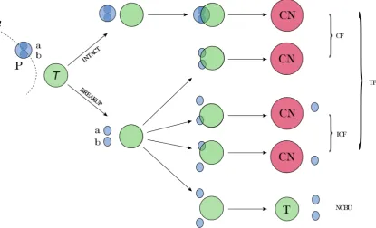
Figure 1.4: A representation depicting important reaction channels for
colli-sions of a two-cluster (a, b) weakly-bound nucleusP with a target nucleusT.
A compound nucleus is formed whenP and T penetrate their mutual barrier
radius. WhenP survives intact at the barrier, or whenP breaks up and either
or both fragments (a, b), pass through thea, b+T barrier radii. The former is
called complete fusion (CF) while the last, incomplete fusion (ICF) occurs if
eitheraorb is captured by the target. If both fragments are obtained, then
it is also called complete fusion. The sum of complete and incomplete fusion
is called total fusion (TF). Reactions, where both breakup fragmentsa, bare
not captured by the target are referred to as no-capture breakup (NCBU) [29]. Illustration adapted from Ref [29].
nuclei, by making precision measurements aimed at investigating these breakup processes, and particularly, in observing how these breakup processes affect complete fusion [28, 47–51, 51–62, 62–72].
1.4.1 Suppression of Complete Fusion
systems, with the typical suppression of the complete fusion cross-section being ≈ 30%[28, 49–51, 58, 64–72]. Along with complete fusion, other reaction pathways can occur and are illustrated in figure (1.4).
In weakly-bound systems, complete fusion can occur in two ways: from the capture of the projectile by the target [described in section (1.2)], and breakup followed by capture of both fragments. Both lead to the same reaction product. As a result, the two processes cannot be differentiated. If after breakup occurs, only one of the fragments is captured by the target, then this is known as incomplete fusion (ICF). The case where no breakup fragments are detected is termed ‘no capture breakup’ (NCBU). It is suggested that fusion suppression above the barrier is due to breakup of the projectile into fragments before passing inside the fusion barrier leading to ICF and NCBU, and reducing the likelihood for complete fusion [49].
1.4.2 Relationship Between Breakup and Fusion Suppression
0.0 1.0 2.0 3.0 4.0 5.0 6.0 7.0 8.0
(a)
0.0 1.0 2.0 3.0 4.0 5.0 6.0 7.0
0.8 0.9 1 1.1 1.2 1.3 1.4 1.5
σfus
/
R
2 b
Ec.m./Vb
(b)
7Li + 209Bi 18O + 198Pt
SBP calc.
0.74 × SBP calc.
9Be + 208Pb 13C + 204Hg
SBP calc.
[image:32.595.65.471.110.624.2]0.70 × SBP calc.
Figure 1.5: Experimental data taken from Ref [58], showing the reduced
complete fusion cross-sections, for (a)7Li +209Bi and 18O +198Pt reactions
and (b)9Be +208Pb and13C +204Hg reactions. They show that cross-sections
for reactions involving weakly-bound nuclei are lower than for reactions of well-bound nuclei. The dashed lines are single barrier penetration model
calculations which describe the data for the 18O + 198Pt and 13C + 204Hg
could be extrapolated to above-barrier energies and therefore be used to predict the above barrier fusion suppression due to breakup [25], leading to the development of a three-dimensional classical dynamical model that relates above-barrier CF and ICF cross-sections with below-barrier NCBU cross-sections [74, 75].
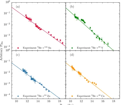
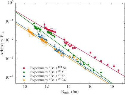
In this thesis, breakup of 9Be incident on targets of 124Sn, 89Y, 64Zn and 40Ca were measured, and data were used to explore several fundamental questions. What are the systematics in the suppression factors due to breakup in decreasing proton number Z? Is there a target dependence? Does the breakup strength, and therefore potential to influence fusion, decrease with decreasing targetZ? These measurements along with Cook et al. [26], will be valuable inputs into quantum models, which account for breakup in stable and unstable weakly-bound nuclei.
1.4.3 The Need to Develop a Classical Trajectory Model
The fully quantum coupled channels (CC) approach [34] to nuclear reactions fails to describe fusion with weakly-bound nuclei because low-lying unbound states cannot be included. Instead, calculations are carried out using continuum discretised coupled channels (CDCC) [76–82], an extension of the CC approach that allows the treatment of couplings to unbound continuum states above the breakup threshold, developed for describing three-body nuclear reactions. The approach can make reliable estimates of the NCBU and total fusion (CF + ICF) processes. The major disadvantage of this method is that ICF and CF process cannot be distinguished, and transfer triggered breakup cannot be currently modelled [79]. This shortcoming is present in all other existing quantum models as well.
as KOOKABURRA∗, a next generation code in a similar vein to PLATYPUS [74, 75, 83, 84], allows a consistent calculation of breakup, incomplete, and complete-fusion cross-sections. It is used to estimate the above-barrier suppression of complete fusion for reactions of9Be, by tracking the trajectories of the breakup fragments and is delineated in Appendix (A).
1.5
Thesis Outline
The first part of this thesis is aimed at understanding the breakup mechanisms for the weakly-bound cluster nucleus of 9Be in reactions with medium to light mass nuclei, using a large-area high-efficiency silicon detector array ‘Breakup Array for Light Nuclei’ (BALiN). This work is complementary to previous work that studied the interactions of9Be incident on heavier targets [26, 27]. The aim is to quantify the breakup of9Be across the nuclear chart, gaining knowledge of how breakup affects fusion as the target mass is changed.
The second part of this thesis describes developments, made concurrently with the9Be measurement, to enable experiments with light weakly radioactive ion beams (RIB) at the ANU. These beams include 8Li and the exotic 6He halo nucleus. In particular this thesis describes the design, development and commissioning of a tracking detector system based around two twin Parallel Plate Avalanche Counters (PPACs), a critical element of the SOLEROO separator at the ANU [16, 17]. These detectors allow tracking and tagging of the particles that pass through them and thus lead to a virtually pure beam of the desired species.
The layout of the thesis is as follows. Chapter 2 gives details of 9Be beam production using the ANU 14UD accelerator, the experimental setup, data analysis and results from below-barrier breakup measurements of the weakly-bound 9Be nucleus, incident on targets ranging in mass number from 40 to 124. Chapter 3 describes the unique features of RIB production and provides a description of SOLEROO, the RIB capability developed at the ANU, and uses an in-flight transfer
∗Private communication with E. Simpson, Australian National University (Australia). The
but soon the remoteness of the turmoil of life and the inspiring influence of the altitude calm your blood; your step gets firm and sure and you begin to look -for dizzier heights.
Nikola Tesla (1856 - 1943)
2
9
Be Breakup Measurements
To understand the mechanisms and systematics of breakup of9Be, charged coincidence particle measurements of the breakup of 9Be on targets of 40 ≤ A ≤ 124 were performed at below barrier energies using a highly pixellated large solid angle charged particle detector known as ‘BALiN’.
This chapter describes the production of the9Be beam, the detector array, how the coincident breakup fragments were identified, and the analysis used to understand the systematics and mechanism in breakup. From the measured data two important quantities are derived: The three-body reconstructed reaction Q-values, and the relative energies of the breakup fragments. Together these quantities give an insight into the dynamics of the breakup mechanism and allow identification of the physical processes that lead to the breakup of the projectile-like nucleus. The data presented in this chapter show that breakup following neutron transfer dominates the total breakup yield for all systems studied. At sub-barrier energies, long-lived states in the projectile-like nucleus break up asymptotically far away from the target nuclei, on the outgoing trajectories. At above-barrier energies, nuclei in these long-lived states pass inside the fusion barrier, and so cannot contribute to complete fusion suppression. However, breakup following neutron stripping from 9Be can form 8Be in its 2+ excited state which has a short mean lifetime of 4.35 × 10⁻²²s [85, 86], decaying into two α-particles. At above-barrier energies, this can result in breakup
Figure 2.1: A schematic layout of the SNICS ion source, adapted from
Ref [29]. The positively charged caesium ions are accelerated towards a
cathode, sputtering sample material on impact. Some of the sputtered atoms pick up an electron while passing through the neutral caesium film on the surface of the cooled cathode, thus forming a beam of negatively charged ions.
on the incoming trajectory, reducing the probability of complete charge capture, and thus suppress complete fusion.
2.1
Production of Accelerated
9Be beams
2.1.1 Negative Ion Source
As a tandem accelerator, the 14UD requires negatively charged ions to be injected. Negative ions are produced by an NEC SNICS II (Source of Negative Ions by Caesium Sputtering) ion source, shown in figure (2.1). The Caesium is located in a reservoir which is heated typically to > 100◦C, forming a vapour. This vapour fills the region between the cathode and the ioniser. The cathode containing the source sample is typically cooled to just below room temperature, resulting in some caesium vapour condensing onto the cool surface of the cathode, forming a neutral layer of caesium atoms. The caesium vapour also comes into contact with the surface of the ioniser made of tungsten as it has greater electron affinity than caesium, and heated to a temperature of ∼ 1000◦C and leaves behind an electron. The charged positive caesium ions emerge from the ioniser and are accelerated towards the cathode, biassed at -5kV. They sputter atoms of the sample material in the cathode on impact. Some of the sputtered atoms will pick up an electron when passing through this neutral caesium layer which had condensed on the surface of the cathode. This forms the beam of negatively charged ions which are extracted from the SNICS by the positively biassed extractor electrode [91–93].
The beam produced using the SNICS for this thesis work was 9Be, extracted as mono-, di- and trihydride negative ions. This is achieved by introducing ammonia (NH3) gas into the volume around the sample. The hydride ions (9Be H−) have a larger electron affinity of 2.8 eV compared with the 9Be− electron affinity of 0.195 eV, resulting in a much greater beam current.
qv⊥B = mv
2
⊥
r =
2Ea
r . (2.1)
As all the ions have the same energy and charge state, the inflection magnet acts as a mass separator, by bending ions of different mass through different r:
r= mv⊥
B =
√
2mEa
B . (2.2)
Having passed through the mass selection magnets, the ions are then injected into the 14UD accelerator.
2.1.2 14UD Accelerated Beams
A schematic layout of the 14UD accelerator is shown in figure (2.2). The accelerator tank is filled with inorganic sulphur hexafluoride (SF6) gas at a pressure of ∼700 kPa. This is to prevent electrostatic discharge caused by the high potentials. There are two stages of acceleration in the 14UD. In the first, ions enter the 14UD from the mass selection inflection magnet and are accelerated from ground potential to the positively charged central terminal potential, giving ions of energy:
E = (VT +Va)e. (2.3)
Here E is the ion energy in MeV,VT is the potential at the terminal and Va, the ion source potential, both in MV. The charging of the terminal happens by using the Pelletron charging system. The charging chains are made of metal pellets connected by insulating nylon links [94]. Induction electrodes at the base of the column induce positive charge onto each pellet moving up towards the terminal. As the pellets leave the terminal, a negative charge is produced on the pellets, using induction electrodes once again. This results in a net positive charge at the terminal. At the terminal the negative ions pass through a carbon stripper foil∗, where electrons are stripped. The ions emerge with a distribution of positive charges whose mean can be described by
the semi-empirical formula for particles passing through a solid [95, 96],
¯
q =Z
1 +Z0.75 3.86
r
E A
!−1.67
−0.6
. (2.4)
Here q¯is the mean charge state, E is the ion energy at the terminal in (MeV), Z is the atomic number, and A is the mass number of the ions. At this point, any molecular ions break up to make elementary ions. For example 9BeH− now becomes (9Be x+ and H+). All the ions are at this stage positively charged and will undergo a second phase of acceleration away from the positively charged terminal to ground potential. The energy of the ions exiting the accelerator can now be defined by:
E = (1 +q0)VTe+Vae, (2.5)
where q0 is the charged state of the accelerated ion after stripping.
When the beam leaves the accelerator, it comes to the energy selection electro-magnet shown in figure (2.2). Here the desired beam energy can be selected by appropriately setting the magnetic field strength based on Eqn (2.2). The magnetic field is measured by a nuclear magnetic resonance probe.
Table 2.1: The range of beam energies for the projectile-target combinations
used in these experiments and the areal densities of the targets. Vb is the
fusion barrier in the centre-of-mass frame.
Projectile Target Areal density [µg/cm2] EBeam[MeV] Ecm[MeV] Vb [MeV] E/Vb
9Be 40CaF
2 20−50 12.50, 14.00 10.20, 11.43 12.02 0.85, 0.95 64Zn 100 15.70, 17.70 13.76, 15.52 16.20 0.85, 0.96 89Y 60 20.80, 23.00 18.89, 20.89 21.80 0.87, 0.96 124Sn 200 23.00, 26.40 21.44, 24.60 25.87 0.83, 0.95
controlling the beam pulsing system and are used in time-of-flight (ToF) analysis.
2.2
Experimental Setup
Following the energy selection magnet, the beam is transported to the target area. The experiment was carried out in the CUBE scattering chamber shown in figure (2.3). This is a purpose vacuum chamber, which is also home to large-area multi-wire proportional counter (MWPC) gas detectors, utilised for fission measurements [102–105]. A selection of up to 7 targets and 1 aperture can be mounted on a multi-target ladder which is computer controlled. A tuning aperture with a central 2 mm hole is placed in the path of the beam, mounted on the hub that holds two double-sided silicon strip detectors (DSSDs), downstream from the target. It serves, when used in combination with a beam current measurement from the beam dump (downstream of CUBE), to allow operators to (a) minimise the beam spot size and (b) maximise its intensity at the centre of the target. Charged breakup fragments were detected using the ‘Breakup Array for Light Nuclei’ (BALiN), a large area position sensitive detector array that consists of four DSSDs, as shown in figure (2.4) (a) and (b).
2.2.1 Targets and Beam Energies
For these experiments, the 9Be pulsed beam was incident on targets of mass 40 ≤ A
Figure 2.3: Centre of the photograph shows the BALiN array in the front-back configuration, placed inside the CUBE chamber. Not shown in the photo is the CUBE chamber lid, which surrounds the experimental set up and allows
(a)
(b)
MONITOR
DSSD
-A
DSSD
-B DSSD-C
DSSD -D
TARGET
BEAM
TARGET BEAM
onto ≈ 10µg/cm2 natC backings. The 89Y target had an Al backing of 30µg/cm2, while the 64Zn target was self-supporting. The targets were oriented at 45◦ to the beam axis, with the plane of the target facing BALiN detectors and their backing, if present, facing downstream. Apart from the carbon support, and the fluorine in the calcium target, other light impurities, for example, oxygen, may be present in the targets, as materials may change chemical composition over time. The targets were chosen because above barrier complete fusion cross-sections existed in the literature for these targets [51, 67–72, 106].
Each target was measured at two different beam energies, both below the barrier. Making measurements at below-barrier energies reduces the influence from competing capture processes like incomplete fusion (ICF) and complete fusion (CF), which would be dominant at above-barrier energies. This makes interpretation of the results cleaner and clearer. For the9Be + 124Sn reaction, the experimental centre-of-mass energies were 21.44 and 24.60 MeV, corresponding to 0.83 and 0.95 of the barrier energy Vb, taken from Ref [106]. The 9Be + 89Y reaction was measured at energies 18.89 and 20.89 MeV, corresponding to 0.87 and 0.96 of Vb, taken from Ref [70]. For 9Be + 64Zn reaction, the measurements were carried out at 13.76 and 15.52 MeV, corresponding to 0.85 and 0.96 Vb, taken from Ref [67]. For the9Be +40Ca reaction, the energies were 10.20 and 11.43 MeV, corresponding to 0.85 and 0.95 Vb, calculated using the São Paulo potential [107], as no reported measured barrier energy in the literature exists for this system.
2.2.2 Detector Configuration
For these experiments, the BALiN detectors were mounted in a front-to-back config-uration. Each detector∗ has an active area of 540 cm2. The four DSSDs labelled A to D, in figure (2.4) were mounted on two hubs. The plane of the detectors was at an angle of 45◦ and mounted on a hub coaxial with the beam axis as shown in the cross-sectional view of the experimental set up, in figure (2.5). The array was placed in this arrangement to maximise coverage of capturing coincident breakup events;
TARGET
Al MASK
BEAM 45.0
HUB
DSSD o
45.0o 45.0o
o
50
45.0 55o
DSSD
Al MASK
MONITORS
Up & Down (Out of Plane)
HUB
Figure 2.5: A cross-sectional view of the experimental set up adapted from Ref [29,89], showing only one forward and one backwards angle DSSDs. During the experiment an aluminium mask was placed in the chamber, in such a position, to shield the two forward DSSDs from an intense elastic count rate.
for these projectile-target combinations, a significant number of breakup fragments are expected to be at forward angles.
All four DSSDs are 400 µm thick, with units A, B taking ≈ -120 V of bias, D taking ≈ -108 V of bias for full depletion, while unit C is fully depleted∗ with -45 V. Placed in front of each DSSD is a Mylar foil of 0.7 µm thickness to stop the low energy electrons produced by the interaction of the beam and target. Each detector has 16 arcs and 8 sectors. The intersection of each arc and sector defines a pixel, which over all four detectors, gives 512 pixels. This allows fine-grained position information to be obtained.
Each pixel is separated from the neighbouring pixels by a 100µm of insulating partition. The forward angles of the detector were shielded to avoid a high elastic count rate. This gave an angular coverage of 55◦ to 84.5◦ (θ) in the forward hemisphere, and 110◦ to 170◦ in the backward hemisphere. Each detector has an azimuthal angle coverage of 72◦ (φ) giving a total coverage of 144◦ (φ) over all 4
∗The low depletion voltage compared with A,B and D is suspected to arise from detector C
detectors in the front and back arrangement of the DSSDs. Experimental data were normalised by two surface barrier monitor detectors, fixed at ±50◦ with respect to the beam axis. At sub-barrier energies, the elastic scattering events follow Rutherford scattering at these angles.
2.2.3 Signal Processing
Over four DSSD detectors there are 64 arcs and 32 sectors, giving 96 energy and 64 time signals∗ in addition to the two monitor detector signals. All are processed by an electronics set up† shown in figure (2.6).
2.2.4 DSSD Signals to Preamplification
The first stage of signal processing is preamplification. The 64 arcs and 32 sectors were individually amplified using the MESYTEC MPR-16‡ multi channel preamplifiers. These preamplifiers are housed within the CUBE chambers and operate under vacuum. This is done for two reasons. Firstly, to reduce the distance the signals have to travel from the DSSDs, minimising the capacitive loading associated with long cables, and thus improving the signal-to-noise. Secondly, housing the preamplifiers in the CUBE chamber, under vacuum, helps to isolate the preamplifiers from external electronic noise like RF interference, again acting to improve the signal-to-noise. The preamplifiers, mounted on thick aluminium plates thermally anchored to the chamber base, all faced outwards towards the wall of the CUBE chamber to maximise the radiative cooling. The detector bias voltage was supplied to the preamplifiers from an ORTEC 710 quad§1 kV bias supply. All six MPR-16 preamplifiers were grounded
∗Time signals taken from BALiN’s arcs only.
†Units shown in figure (2.6) and not defined in text: (FIFO) ‘Fan-in/fan-out’, used to make
multiple outputs from one or more analog or logic inputs. (CFD) ‘constant fraction discriminator’, designed to mimic the mathematical operation of finding a maximum of a pulse by finding the zero of its slope. (TFA) ‘Timing Filter Amplifier’, designed to shape pulses and optimise the signal-to-noise ratio for timing measurements. (RF) ‘Radio Frequency’, a reference signal used in time of flight (ToF) measurements. (SCALER), used to record signals that occur too rapidly to be recorded individually and a (PRE-SCALER), used to reduce a high frequency signal to a lower frequency by integer division [108, 109] .
Figure
2.6:
BALiN
electronics
set
up,
adapted
from
Ref
[29
to a clean earth also used for the subsequent signal processing and data acquisition system.
2.2.5 Preamplification to Amplification
The analogue signals are then sent to 6 MEYSTEC STM-16 multi channel amplifiers. The STM-16 is a linear pulse-shaping and timing amplifier which provides the energy and time information from the preamplifier output pulse. The energy signal has a Gaussian pulse shape whose height is proportional to the particle energy. The timing signal is a negative fast logic pulse corresponding to signal passing threshold (leading edge timing). The analog energy outputs are sent to CAEN V785 32-channel multi-event peak sensing angalog to digital converter (ADC) and the timing outputs are processed through a CAEN 64-channel V1190B 100 ps multi-hit time to digital converter (TDC). At this point the signals registered in BALiN are now digitised.
2.2.6 DAQ Trigger Condition
A trigger signal needs to be sent to the data acquisition system (DAQ) to record the data. The DAQ was triggered by demanding that at least one arc of any detector received a signal, or either monitor detector received a signal. This was achieved by chaining the multiplicity output of each arc amplifiers to each other, requiring only multiplicity = 1. A logical ‘OR’ condition with either of the monitor detectors generated the DAQ trigger. The measurements were made in singles mode, requiring the DAQ to read simultaneously the output of all arcs and sectors which fired, recording events with all multiplicities. Higher multiplicity requirements were imposed in off-line analysis. Data was collected using DCP (data collection software running on a VMS cluster), and all subsequent off-line analysis were done in ROOT∗, an object orientated data analysis framework [110].
2.3
Breakup Analysis
The breakup analysis of 9Be incident on targets of 40Ca, 64Zn, 89Y and 124Sn follow the methods laid out in Ref [26]. This work focused on measurements of breakup in reactions of 9Be with 144Sm,168Er, 186W, 196Pt, 208Pb, and209Bi at energies below the barrier. Therefore to have a comparable data set concerning breakup reactions with 9Be, completing the stable elementary range of the periodic table, consistency in the analysis is needed. Techniques applied in this work, taken from Ref [26] are as follows:
(i) Identification of breakup modes, section (2.5);
(ii) Determining breakup that occurs close to the target or asymptotically far from the target, section (2.6);
(iii) Efficiency corrections, subsection (2.7.2) and (2.7.3);
(iv) Simulation of efficiency for events where θ12 is outside coverage of the array, subsection (2.7.3);
(v) Determination of near-target breakup probabilities, subsection (2.7.5);
A brief discussion on the listed applied techniques will be presented later on in this chapter. Further information and justification can be found in Ref [26].
2.3.1 Analysis of Raw Data
(deg)
φ
50 100 150 200 250 300 350
(deg) θ 20 40 60 80 100 120 140 160 180 h
Entries 2.000549e+07 Mean x 136.7 ± 0.01662 Mean y 79.47 ± 0.005547 RMS x 74.29 ± 0.01175 RMS y 24.8 ± 0.003923 Integral 1.999e+07
1 10 2 10 3 10 h
Entries 2.000549e+07 Mean x 136.7 ± 0.01662 Mean y 79.47 ± 0.005547 RMS x 74.29 ± 0.01175 RMS y 24.8 ± 0.003923 Integral 1.999e+07 Elastic.T1:Elastic.P1
A B C D
Figure 2.7: Angular coverage of individual detectors of the array, for the
reactions of9Be incident on 124Sn atEBeam = 26.40 MeV.
293◦ for detectors A-D, respectively. The finite pixel size results in uncertainty in determining the exact location of interaction. Each particle is thus randomised in (θ, φ), within the physical boundaries of its pixel by assuming a uniform distribution of events over the pixel. The angular coverage on average per pixel is ≈ 3◦ in θ and 9◦ in φ. The experimental (θ,φ) coverage is shown in figure (2.7). The determination of the angles is estimated to be better than 1◦.
(deg)
θ
60 80 100 120 140 160
Arc Energy (MeV)
0 5 10 15 20 25 30 h
Entries 2.000549e+07 Mean x 79.47 ± 0.005547 Mean y 12.87 ± 0.00203 RMS x 24.8 ± 0.003923 RMS y 9.076 ± 0.001436 Integral 1.999e+07
1 10 2 10 3 10 4 10 h
Entries 2.000549e+07 Mean x 79.47 ± 0.005547 Mean y 12.87 ± 0.00203 RMS x 24.8 ± 0.003923 RMS y 9.076 ± 0.001436 Integral 1.999e+07
Elastic.E:Elastic.T1
Figure 2.8: Energy calibrated singles spectrum, displayed across the full
angular coverage of the array for9Be incident on124Sn atEBeam= 26.40MeV.
2.3.2 Selecting True Breakup Events
Figure 2.9: Time-of-Flight (ToF)vs. Energy of the fragments,9Be incident
on124Sn at EBeam= 26.40 MeV.
The radio frequency (RF) signal from which the beam pulsing was referenced was used to obtain the time-of-flight (ToF) taken from the target to the BALiN array with respect to this RF signal. Combining this ToF information with the measured energy in BALiN allowed for particle identification, as shown in figure (2.9). While in principle ToF can be converted to mass, this conversion is made complex due to the time walk of the leading edge timing used in the experiments. In this thesis ToF information was not required to identify the dominantα+ αbreakup partition. However in experiments using6Li and 7Li, ToF information proved crucial in identifying breakup partitions.
addition, from plotting the raw calibrated energy of two events E1 vs. E2 shown in figure (2.10), there are indications of spurious coincidences that are not the result of ambiguities in position identification. Events found in the horizontal and vertical bands [indicated by the dashed line figure (2.10)], arise from one particle having an energy equal to that expected of elastically scattered 9Be at the given beam energy. Events in these bands are random coincidences between an elastically scattered 9Be and another fragment of lower energy (or at the intersection of these two bands, correspond to coincidences between two elastically scattered particles).
Many of the events that lie on the diagonal bands correspond to true breakup events. The correlated energies of the coincident particles indicates that they may be fragments from breakup. Discrete bands show breakup of different parent-nuclei or parent-nuclei with different kinetic energies. However, not all events with diagonal energy correlation are true breakup events. For example, consider events where the two signals are recorded in neighbouring pixels of the same DSSD. Events that meet this condition can be true two particle events with a small opening angle between them (for example, 8Be ground state decay). Alternatively, they could have arisen from charge sharing (cross-talk) from a single particle that was incident on an inter-strip separation of a DSSD causing the charge to be collected in two arcs or two sectors. The majority of events along the solid black line in figure (2.10) arise from charge sharing from a single 9Be elastically scattered particles. Other sources of spurious coincidences include random coincidences with detector noise or a scattered projectile, from lighter impurities in the target, and low fragment energy coincidences from p and α transfer.
Figure 2.10: Energy of fragments E1 vs. E2 for coincidence events in
the reaction of 9Be incident on 124Sn at EBeam = 26.40 MeV, E/Vb = 0.95.
Diagonal bands are events consisting of breakup fragments originating in the same process. The black band indicates a significant number of events from cross-talk (a single particle incident on the inter-strip separation, simulating a
coincidence event, of elastically scattered particles orα-particles from breakup
of 9Be). The dashed line corresponds to random coincidences between an
elastically scattered9Be and another fragment of lower energy. Events within
the black triangle consists of events from spurious coincidences from light
impurities in the target and possibly coincidences from p andα transfer.
2.4
Derived Energy Variables
Once the false coincidence events are removed, theαpairs resulting from the breakup of 8Be and 9Be can be seen in the measured energy of the breakup fragments shown in figure (2.11). The breakup can be characterised from the reconstructed spectra of the reaction Q-value. The Q-value reconstruction is done assuming projectile breaks up into the two detected charged particles, labelled 1 and 2. The Q-value is determined by:
Q=E1+E2+Erecoil−Elab. (2.6)
(MeV)
1
E
2 4 6 8 10 12 14 16 18 20 22 24
(MeV)
2E
2 4 6 8 10 12 14 16 18 20 22 24 hEntries 207830 Mean x 10.42 ± 0.003287 Mean y 10.43 ± 0.003288 RMS x 1.499 ± 0.002324 RMS y 1.499 ± 0.002325 Integral 2.078e+05
5 10 15 20 25 30 h
Entries 207830 Mean x 10.42 ± 0.003287 Mean y 10.43 ± 0.003288 RMS x 1.499 ± 0.002324 RMS y 1.499 ± 0.002325 Integral 2.078e+05
Data.AE2:Data.AE1 {aa.Id}
Figure 2.11: Energy of fragment 1 (E1) against fragment 2 (E2). Same figure
as figure (2.10), but all false coincident events have been removed, leaving only
events from the breakup of9Be.
mylar foil, aluminium layer and silicon dead-layer, Elab is the lab energy of the beam particle, after traversing half the target thickness. Knowledge of the undetected recoiling target-like nucleusErecoil is obtained from applying momentum conservation,
− →P
beam =−→P1+−→P2+−→Precoil. (2.7)
The individual components of the recoil nucleus momentum vector are given by:
Precoilx =−P1x−P2x,
Precoily =−P1y −P2y,
Precoilz =Pbeam−P1z −P2z.
(2.8)
Figure 2.12: Reconstructed Q-value spectrum for125Sn through the n-transfer
reaction124Sn (9Be, 8Be)125Sn at EBeam = 26.40 MeV
for 9Be + 124Sn, measured at 26.60 MeV in the lab frame. Clear peaks are visible above Q > -1.57 MeV. These peaks match well with excitation energies in 125Sn (target + n), implying transfer of a neutron from 9Be, forming 125Sn, with a ground state Q-value of +4.069 MeV in its 11/2− state. In the direct-breakup of 9Be, no information from the neutron is acquired as the detector is not sensitive to neutrons. This results in a smear in Q-value, arising from the fact that the neutrons will carry a range of energies. The direct-breakup channels of 9Be → α +α+n (Q-value = -1.57 MeV) and 9Be → 4He + 5He (Q-value = -2.037 MeV), followed with the subsequent fast decay of 5He → α+n = (Q-value = 0.735 MeV) with a lifetime in the order 7×10⁻²²s [85, 86], means that all the 9Be direct-breakup will be below Q-value = -1.57 MeV. Although the majority of events in this region are expected to be from the direct-breakup of 9Be, breakup events may be present from (n + target) transfer reactions resulting in high excitations in125Sn, or from reactions with target impurities. Here, because of the wrong mass assumed in the Q-value reconstruction, the events are spread in energy.
Following n-transfer, it is possible for the 8Be projectile-like nucleus to be in an excited state. This excitation energy will appear in the form of kinetic energy of the two measured α-particles following breakup. By reconstructing the relative energy Erelbetween twoα-particles, information about the state of the projectile-like nucleus at the time of breakup can be obtained and is determined from the expression:
Erel=
m2E1+m1E2−2
√
m1E1m2E2cosθ12 m1+m2
, (2.9)
whereθ12is the reconstructed laboratory frame opening angle between twoαparticles, given by:
cosθ12= cosθ1cosθ2 + sinθ1sinθ2cos(φ1−φ2). (2.10)
Here mi and Ei are the mass and the energy of each fragment. (θi, φi) are the measured scattering angle and azimuthal angle of each particle in a coincidence event.
The reconstructed α−α Erel spectra for 9Be + 124Sn at laboratory energies of 26.4 and 23.0 MeV are shown in figure (2.13). The intense peaks at 92 keV arise from 8Begs decay. The broadening of the 92 keV peak is an effect of the finite energy resolution and angular pixelation of the detector array [28]. The broad distribution peaking at Erel ≈ 3.0 MeV in figure (2.13), originates largely from the 2+ excited state of the 8Be nucleus with large width, and thus short lifetime in the order of
10−22 seconds [86], with a tail extending up to 10 MeV.
Combining both the Q-value and Erel information thus provides an insight into the mechanisms leading to breakup, and will be discussed next.
2.5
Identification of Breakup Modes
Figure 2.13: The measuredα−αrelative energy for9Be +124Sn at laboratory energy of 26.40 MeV (Top) and 23.0 MeV (Bottom)
projectile-target combinations (9Be + 124Sn, 89Y,64Zn and40Ca), as shown in figure (2.14). The spectra have been divided into three regions labelled (1,2,3).
Region (1) 8Begs Breakup
Figure 2.14: Reconstructed Erel against Q-value for all the reactions and
energies studied. Region (1), shown to the left of the vertical dashed line,
contain events from the decay of 8Be from its 0+ ground state. Region (2),
shown to the right of the vertical dashed line contains events from breakup of
8Be from either the high excitation energy tail of the 0+ state or the 2+, 4+
states. Region (3), marked in the dashed box, right of the vertical dashed line
contains events coming from direct-breakup from the decay of 9Be from its
5/2− state. No clear indication of breakup for from the 5/2− state is seen in
pixels [29]. Due to the long mean lifetime, breakup will occur on the outgoing trajectory with the 8Be nucleus travelling essentially at its asymptotic velocity, fully accelerated in the Coulomb field of the projectile-like and target-like nuclei, and is therefore referred to as asymptotic breakup. The8Begs events in this region can come from n-transfer followed by breakup (Q > -1.57 MeV), or from the direct-breakup of 9Be (e.g. 9Be → 8Be + n).
Region (2) 8Be 2+ Breakup
The events in region (2)with largerErel to the right of region(1)predominately arise from breakup of8Be via its 3.03 MeV 2+state. This state has width ofΓ= 1.513 MeV
± 15 keV, which corresponds to a mean lifetime of 4.35 ×10⁻²²s [85, 86]. Another possible source, though unlikely because of the large excitation energy required, is the 11.35 MeV 4+ state excited state of8Be, which has a width of 3.50 MeV, and a similar lifetime [85, 86]. Given the short lifetimes, it is possible that break up can occur close to the turning point (distance of closest approach). These events are thus described as near-target breakup. As the breakup occurs in close proximity to the target, its interaction with the breakup fragments can distort and affect their trajectories, therefore smearing the distribution of Erel. Erel is thus not a direct measure of the excitation energy of the projectile-like nucleus in this region, which is reflected in what is seen in figure (2.13), showing a very broad distribution for near-target events. At above barrier energies if breakup occurs prior to the turning point, it is possible for the one of the breakup fragments to fuse with the target-like nucleus leading to an increase of the ICF cross-section and a suppression of the CF. It is also possible for both fragments to be captured by the target-like nucleus, a process indistinguishable from CF.
Region (3) 9Be Direct-Breakup

![Figure 1.5: Experimental data taken from Ref [58], showing the reducedwell-bound nuclei.complete fusion cross-sections, for (a) 7Li + 209Bi and 18O + 198Pt reactionsand (b) 9Be + 208Pb and 13C + 204Hg reactions](https://thumb-us.123doks.com/thumbv2/123dok_us/1804678.135512/32.595.65.471.110.624/figure-experimental-showing-reducedwell-complete-sections-reactionsand-reactions.webp)
![Figure 2.1:A schematic layout of the SNICS ion source, adapted fromRef [29].The positively charged caesium ions are accelerated towards acathode, sputtering sample material on impact](https://thumb-us.123doks.com/thumbv2/123dok_us/1804678.135512/38.595.60.482.85.295/figure-schematic-positively-caesium-accelerated-acathode-sputtering-material.webp)