This is a repository copy of
Design of a Modular Continuum Robot Segment for use in a
General Purpose Manipulator
.
White Rose Research Online URL for this paper:
http://eprints.whiterose.ac.uk/145152/
Version: Accepted Version
Proceedings Paper:
Castledine, NP, Boyle, J and Kim, J orcid.org/0000-0002-3456-6614 (2019) Design of a
Modular Continuum Robot Segment for use in a General Purpose Manipulator. In: 2019
IEEE International Conference on Robotics and Automation (ICRA). 2019 International
Conference on Robotics and Automation (ICRA), 20-24 May 2019, Montreal, Canada.
IEEE , pp. 4430-4435. ISBN 978-1-5386-6027-0
https://doi.org/10.1109/ICRA.2019.8794249
©2019 IEEE. Personal use of this material is permitted. Permission from IEEE must be
obtained for all other uses, in any current or future media, including reprinting/republishing
this material for advertising or promotional purposes, creating new collective works, for
resale or redistribution to servers or lists, or reuse of any copyrighted component of this
work in other works.
[email protected] https://eprints.whiterose.ac.uk/
Reuse
Items deposited in White Rose Research Online are protected by copyright, with all rights reserved unless indicated otherwise. They may be downloaded and/or printed for private study, or other acts as permitted by national copyright laws. The publisher or other rights holders may allow further reproduction and re-use of the full text version. This is indicated by the licence information on the White Rose Research Online record for the item.
Takedown
If you consider content in White Rose Research Online to be in breach of UK law, please notify us by
Design of a Modular Continuum Robot Segment for use in a General
Purpose Manipulator*
Nicholas P. Castledine
1,2, Jordan H. Boyle
1and Jongrae Kim
1Abstract— This paper presents the development of a tendon-driven continuum robot segment with a modular design, simple construction and significant lifting capabilities. The segment features a continuous flexible core combined with rigid interlocking vertebrae evenly distributed along its length. This design allows bending in two degrees of freedom while minimising torsional movement. The segment is actuated by two antagonistic tendon pairs, each of which is driven by a single geared DC motor. Modularity is achieved by embedding these motors in one end of the segment, avoiding the need for a bulky actuation unit and allowing variable numbers of segments to be connected. The design features a large hollow central bore which could be used as a vacuum channel for suction-assisted gripping or to allow ingress and egress of fluids. The design process goes through four iterations, the final two of which are subjected to quantitative experiments to evaluate workspace, lifting capabilities and torsional rigidity. All iterations are fabricated using multi-material 3D printing, which allows the entire structure to be printed as a pre-assembled unit with the rigid vertebrae fused to the flexible core. Assembly is then a simple case of inserting the motors and connecting the tendons. This unconventional manufacturing approach is found to be efficient, effective and relatively cheap.
I. INTRODUCTION
Loosely inspired by biological structures like snakes or elephant trunks, hyper-redundant robots are a class of robots characterised by elongated bodies or appendages that bend in smooth curves along some or all of their length. This class can be subdivided into serpentine robots, which have a large number of discrete rotational joints, and continuum robots, which rely on deformation of a flexible material [1]. These approaches are functionally similar, but the use of soft materials in continuum robots tends to make them cheaper, more robust and easier to control thanks to their ‘mechanical intelligence’ [2], but this comes at the expense of reduced control precision and power output. These approaches have been used successfully to create snake or worm-like mobile robots, but here we will focus on their use in arms or manipulators.
Hyper-redundant arms can be designed with actuators integrated into the curvature section (‘intrinsically actuated’), or located somewhere else, such as in the base (‘extrinsically actuated’). Intrinsic actuation is more commonly used in continuum arms and is often based on pneumatic actuators, because they are relatively easy to integrate into a flexible
*This work was supported by the EPSRC Research Grant, EP/N010523/1, Balancing the impact of city infrastructure engineering on natural systems using robots.
1School of Mechanical Engineering, University of Leeds, Leeds, UK 2Email: [email protected]
structure. This has the advantage of potentially allowing ac-tuation of extension, torsion and bending simultaneously, but at the expense of relatively low force generation capabilities and the need for complex tube routing and external pressure regulation hardware [3]. Due to the high strain required for actuation, actuation rates can be slow and precision control can be challenging [4]. A representative example of this approach is OctArm, a multi-section continuum arm actuated by air-muscles that uses the distal segment to wrap around objects for manipulation [5]. This arm had a tendency to twist into complex shapes in response to applied end forces, due to the flexibility of the structure. Indeed, a lack of rigidity, including torsional rigidity, is one of the main factors that limits the lifting capability of continuum arms.
Serpentine arms are usually extrinsically actuated via cables or ‘tendons’ in a way that is loosely inspired by the longitudinal muscle fibres of worms and octopus arms [2]. Forces generated by actuators (typically housed in the base) are transferred to attachment points along the arm to generate bending torques. A key advantage of this approach is that conventional rigid actuators like electric motors, which are relatively powerful and controllable, can be used. However, for an arm with multiple independent bending segments (as is typically required), routing the actuation tendons for distal sections through proximal sections causes some issues. Long tendons can experience significant frictional losses, and there is a limit to how many tendons can fit in the arm’s circumfer-ence. There is also the problem of passive coupling between sections, which complicates the kinematic modelling [6]. The most mature example of a tendon-actuated serpentine arm is the one produced by OC Robotics. The arm was designed for working in hazardous environments like nuclear reactors, and has a hollow central core to enable fitting of a large range of end effector tooling. Most of the issues associated with tendon actuation have been solved through precision engineering and advanced control [7], but the system is extremely costly and portability is limited by the presence of a very large base unit housing the actuators.
also allowing extension and contraction in two sections. An arm with rigid vertebrae connected by spherical joints around an elastic backbone was described in [10]. It has good torsional stiffness due to torsional rigidity of the backbone and friction between the vertebrae, but it also relies on a large actuation module. Interlocking vertebrae providing torsional stiffness were also used in [11], but each joint was only capable of bending in one degree of freedom. A modular robot on the surgical scale controls each adjoined segment from a centralised wireless controller, with flexible fluidic actuators fed from a central piping system passing through each segment. This design also relies on the central controller for power and pressure regulation [12].
Informed by a wide range of prior work, our design incorporates a number of features that we believe are the best compromise for a hyper-redundant robot module. A tendon-based design with actuators embedded in each segment will give powerful actuation while avoiding tendon interference and enabling easy reconfigurability, and a compliant back-bone will be combined with rigid interlocking ‘vertebrae’ for ease of manufacturing and good torsional rigidity. The paper is organised as follows: Section II presents the development process of the arm based on an outlined initial concept to get to the current arm specification. Section III presents the testing to define and compare the lifting and workspace capabilities of the latest two arm segment designs. Section IV contains the conclusion and Section V gives recommen-dations for future work.
II. SEGMENTDEVELOPMENT A. Overall Concept
This paper presents the development of tendon driven continuum robot segment, designed with an emphasis on versatility to accept a wide range of end effectors and be used in varied applications. A continuous central bore can be used to provide suction to the tip for grasping assistance, or transport liquids for ingress/egress. The number of connected segments would be limited by their weight in conventional manipulation applications, but would be theoretically unlim-ited if used as a mobile snake-like robot or as an underwater manipulator where buoyancy would counteract weight. To achieve this flexibility in application we will ultimately develop a standardised inter-segment interface, but the focus of the current paper is the design of the actuation segment itself.
Similar to previous continuum robots the segments have a continuous flexible backbone, but attached to this are a series of equally spaced rigid disks or ‘vertebrae’ similar to those found in a typical serpentine robot, making it a hybrid design. These vertebrae act as guides for the actuation tendons and, in later iterations of the design, incorporate an interlocking mechanism for torsional rigidity. The segment is extrinsi-cally actuated by four tendons arranged equally around the circumference and travelling the entire length of the arm. They operate in antagonistic pairs, one for each degree of freedom, with each pair connected to a single motor via a dual spool such that one tendon is let out while the other is
reeled in. A four tendon configuration was chosen to allow the use of one motor per pair of tendons, instead of a motor per tendon approach. These tendons are secured at the distal end of the segment. This compact actuation system fits within a short rigid section at one end of the segment, making it fully self-contained. This increases reconfigurability, reduces tendon friction and eliminates interactions between segments. A diagram outlining this basic concept can be seen in Fig. 1. The body of each segment was 3D printed as a pre-assembled unit using a Stratasys Objet1000 multi-material printer, with soft Tango+ material used for the flexible backbone and rigid Vero material for the vertebrae and ends. This approach was very effective in producing functional prototypes quickly and easily, as shown by the first two designs. Assembly was a fairly simple process of attaching the tendons and spools to the motor shafts, press-fitting the motors into their housings, threading the tendons through their guides and securing them at the far end of the segment. Other manufacturing techniques may be investigated after the design is optimised.
B. Preliminary Designs
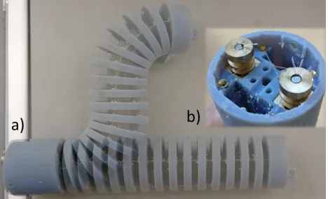
The first iteration (v.0.1) was created to test the actuation concept and the use of multi-material 3D printing for manu-facturing (see Fig. 2). Two Pololu Micro Metal Gearmotors with 298:1 gearboxes are located vertically in the base of the segment, each with a brass double spool on the output shaft which secure a pair of oppositely wound tendons. The motors are connected to an Arduino Nano via a motor shield and controlled by a joystick. Nylon fishing line was used for the tendons, secured at the distal end by tying and gluing them to small posts.
This iteration successfully validated the manufacturing approach, in that the soft backbone allowed for a large range of motion, the vertebrae supported the tendons effectively and all parts fused together into one assembly. The actuation concept proved broadly successful, but two significant issues were identified. Firstly, we found that there is not a one to one ratio of tendon length to tip position. Indeed, with all tendons at equal length the segment could still move through a large range (see Fig. 2) by forming an S-shaped bend. This is inevitable to some degree in an underactuated system such as this, but is magnified by the length of the first prototype. Secondly, the relatively small diameter flexible backbone gave very little torsional rigidity. Together, these two issues meant the segment was incapable of supporting even its own weight in a horizontal position.
C. Refined designs
In the second iteration (v.0.2) we attempted to address these issues by shortening the segment and implementing a soft ‘hinge’ between each vertebrae pair (see Fig. 3). The greater width of these connections gave significantly greater torsional rigidity, but it also limits each joint to one degree of freedom. We therefore alternated the orientation of these hinges by90o
Fig. 1. Overall Concept Layout. a) X axis bending tendon pair. b) Y axis bending tendon pair. c) Hollow continuous low modulus backbone. d) Vertebra containing actuation motors. e) Arm vertebrae. f) End vertebra fixing wire tendons. g) A continuum segment in an arm arrangement.
Fig. 2. Version 0.1 of the continuum segment. a) Showing the range of movement available with all tendons fixed at the same length. b) Top down view of the motor, spool and tendon arrangement.
and are summarised in Table I. By reducing the maximum total bending angle, the tendon lengths better define the segment’s shape. Torsional stiffness was somewhat increased, but not enough to allow horizontal lifting of payloads.
Based on the preliminary designs we concluded that a compliant material cannot provide sufficient torsional rigidity so we developed a novel interlocking vertebrae system. Each identical vertebra features a profiled extruded key and keyway (see Fig. 4). By orienting adjacent vertebrae 90o to each other they interlock to resist rotation while still allowing bending in two degrees of freedom. The motor and tendon architecture remained the same but the nylon fishing line was replaced by 0.7mm braided steel fishing wire to increase strength and reduce stretch. The segment dimensions were also modified as shown in Table I. This third iteration (v.1.1) was subject to a series of quantitative tests which are described in Section III. Ultimately we concluded that there was further room for optimisation, leading to a final round of design refinement. In particular, we sought to increase lifting capability and reduce the play in the interlocking mechanism, while reducing the amount of material used in the vertebrae. Also, we noted during testing that heavy loads would occasionally cause the tendons to slip out of their
Fig. 3. Version 0.2 of the continuum segment with low modulus hinges at alternating orientations between each vertebrae.
spool guides or pull the spools off the motor shafts, due to the sharp angle of the tendon path from the spool to the routing hole.
The final iteration of the design (v.1.2) incorporated a number of changes from the previous. In order to prevent the tendons from slipping from their spool guides, the orientation of the motors was changed to horizontal allowing the spools to be located almost in line with the routing holes, which in turn reduced the tendon’s angle relative to the spool axis. As the tendon loads are now acting perpendicular to the rotation axis, the non-motor end of the spool is supported to reduce the load on the motor shaft. The motors were also changed to 1000:1 gear ratio versions for additional torque. In order to accommodate the horizontal mounting of the motors, the diameter was increased as shown in Table I.
In order to minimise the weight increase associated with the diameter increase, we sought to remove material from the vertebrae while maintaining strength. We therefore con-ducted FEA (Finite Element Analysis) based shape optimisa-tion using the ATOM module in Abaqus (see Fig. 5). Material specifications were taken from the Stratasys website and the boundary conditions were configured to simulate the inter-face between adjacent vertebrae with a torque applied. The optimisation was set up with the Von Mises stress and the volume as the design responses, with the objective function to remove volume while also reducing stress. Critical areas such as the tendon holes and the key/keyway geometry were isolated to prevent volume reduction. This simulation did not take into account the forces from the tendons acting on their guide holes. The optimised geometry was imported into CAD (Computer Aided Design) software and simplified from its abstract shape. The final design for v.1.2 can be seen in Figure 4.
III. EXPERIMENTALEVALUATION
Both iterations of the revised design (v.1.1 and v.1.2) were tested to measure their lifting and workspace capabilities when oriented horizontally, to consider the worst case in terms of gravitational support. Individual vertebra from each version were also tested for torsional strength.
A. Vertebrae Torsional Testing
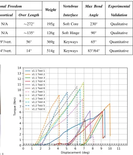
[image:4.612.60.294.253.395.2]TABLE I
CONTINUUMSEGMENTSPECIFICATION.
Version Length No. Vertebrae
OD ID Torsional Freedom Weight Vertebrae
Interface
Max Bend
Angle
Experimental
Validation Measured Theortical Over Length
0.1 190mm 16 40mm 4mm ∼17°/vert. N/A ∼272° 195g Soft Core 230° Qualitative
0.2 122mm 9 40mm 4mm ∼15°/vert. N/A ∼135° 126g Soft Hinge 90° Qualitative
1.1 181mm 10 60mm 7mm 5.6°/vert. 2.9°/vert. 56° 369g Keyways 65° Quantitative
[image:5.612.291.564.77.395.2]1.2 181mm 10 75mm 9mm 1.4°/vert. 1.4°/vert. 14° 514g Keyways 83°/64° Quantitative
Fig. 4. a) Version 1.1 segment. b) Version 1.2 segment. c) Version 1.1 motor and spool arrangement. d) Version 1.2 motor and spool arrangement. e) Interlocking vertebrae at maximum bending deflection.
Fig. 5. a) Simulated torsional loading of single vertebra. b) FEA optimised geometry overlaid on original shape. c) Simplified final vertebra shape.
fixed in a specially designed rig which reproduces the inter-face between adjacent vertebrae by matching the geometry of the keyways. This test will analyse the suitability of the 3D printed material and results, with each testing vertebra printed in the same batch, and in the same orientation in relation to the keyways for manufacturing consistency. The test began at the neutral position (0o
of rotation) and gradually rotated at 0.5 °/s until the point of failure, while recording the associated torque. The results can be seen in Figure 6 and Table II.
[image:5.612.58.312.82.379.2]In order to quantify the rotational play before the interlock-ing mechanism engages, we defined a torque threshold of 0.2 Nm to allow for small amounts of friction in the mounting arrangement. The optimised v.1.2 vertebrae have significantly less play than v.1.1, coming close to the theoretical value
Fig. 6. Torsional tensile loading results of v.1.1 and v.1.2 vertebrae.
TABLE II
TORSIONALTESTINGRESULTS.
Version Break Torque Angle at
Break Play Angle Stiffness
1.1 (0.89 SD)6.1 Nm 8.75° (1.56 SD)5.18° 2.3 Nm/°
1.2 9.9 Nm
(0.99 SD) 5.96°
1.73°
(0.24 SD) 2.1 Nm/°
calculated from the CAD model (shown in Table I). The results show that the v.1.2 vertebrae have a higher average break torque than v.1.1, with a similar average stiffness. The failure mode of the vertebrae was observed to match the high stress areas observed in the FEA, with fractures occurring at the base of the vertebra key.
B. Segment Performance Testing
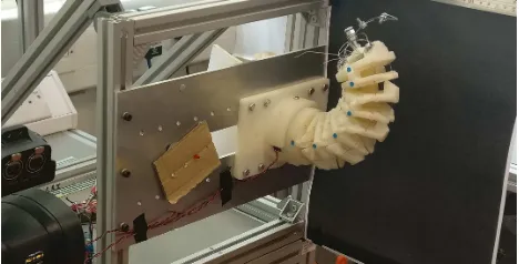
order to scale the image pixels to real dimensions, a ruler was included in shot. Each test was automated for repeatability by a programmed Arduino board piggybacked to a motor controller, set up with a switch to activate the test remotely and safely. Upon test start there was a pause of 3 seconds before the motor activated and a LED (Light Emitting Diode) illuminated, providing a visual reference for in the video for test start. The motor continued to actuate the tendon, creating curvature in the arm until the mechanical limit of motion was reached.
Each segment was tested in two configurations, the first with a tendon pair in the vertical plane which engages one motor only for lifting actuation, and the second rotated 45 degrees from vertical which engages both motors equally for lifting actuation. The tests started with the segment at its lower limit of motion in the workspace and the weight was lifted vertically to the highest achievable point.
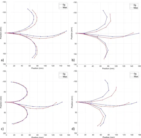
The video footage was analysed in MATLAB to extract the coordinates of each marker in each frame. Figure 8 shows the path of the final (tip) marker in the vertical plane for different payload weights and segment configurations. The capabilities are summarised in Table III, where the maximum payload is defined as the heaviest weight that could be lifted where the tip of the arm is higher than the fixed end at stall point.
The lifting capacity of v.1.2 is significantly greater than v.1.1, and although the unladen speed of v.1.2 is about half that of v.1.1., this gap narrows at maximum payload. As expected, the double tendon configuration lifted significantly more than the single tendon configuration in both versions. The tip trajectory remains relatively consistent with increas-ing payload, particularly in the sincreas-ingle tendon configuration (see Fig. 8 a) and c)). It was also noted that v.1.2. was capable of a slightly greater bending angle range in the single tendon orientation (see Table I), because the non-circular vertebra profile allows more displacement before contact. Due to the current weight of each segment, two configured in series would dramatically reduce the useful payload, therefore further optimisation to reduce the weight will be required.
Figure. 9 shows that the change in workspace (specifically the reach) of the arm under load, is caused by kinking in the mid section. This was measured to be marginally better for the lifts actuated by dual tendons, but this was not a major difference.
Further testing manoeuvring the segment tip out of the vertical plane with an end load showed the effect of the small amount of rotational slack in the arm. It was noted that the direction of the resulting rotation was consistently inwards, as shown in Fig. 10.
IV. CONCLUSIONS
[image:6.612.319.553.50.169.2]We have presented the development of a tendon driven continuum robot segment which is able to strongly resist torsional loads while bending actively and forcefully in two degrees of freedom. By embedding the actuation mechanism in one end of the structure, we have created a relatively
Fig. 7. Performance testing set up, with segment mounted horizontally and a perpendicular high definition camera to track the coloured circular markers during lifting tests. Increasing weights are added to the tip.
TABLE III
PERFORMANCETESTINGRESULTS.
Version Max.
Payload Ave. Unladen Speed
Ave. Max Payload Speed 1.1
(Single) 400g 23°/s 16°/s
1.1
(Double) 700g 31°/s 19°/s
1.2
(Single) 500g 12°/s 12°/s
1.2
(Double) 1300g 15°/s 10°/s
easy to manufacture design, with a high degree of modularity that will ultimately allow great flexibility of application. The segment is intended primarily for use in a general purpose manipulator, but it could also be applied to mobile snake-like robots with further development focused on this application. The work presented here shows that the novel interlocking vertebra mechanism and actuation approach both perform well. The final design (v.1.2) has only14o
of rotational play along its entire length and displays predictable and minimal further deflection under large torsional loads. This is a unique feature among continuum robots which, when combined with the compact but powerful actuation mechanism, gives the segment an impressive lifting capability of up to 1.3kg.
That said, some issues remain to be addressed in future work. Currently, the lifting capabilities are limited by the mechanical strength of the motor gearboxes. Indeed, we observed that the gears would strip before the motors stalled due to the very high (1000:1) reduction ratio, a bending load on the motor shaft, and the small size of the gears. An upgrade to an alternative gearbox system is therefore warranted. Design v.1.2 had significantly less rotational play than v.1.1 as intended, and the breaking torque was increased, giving confidence that the results of our FEA-based shape optimisation are valid.
V. FUTUREWORK
Fig. 8. Change in tip path with increased payload. a) V.1.1 single tendon lifts. b) V.1.1 double tendon lifts. c) V.1.2 single tendon lifts. d) V.1.2 double tendon lifts.
power supply lines to proximal sections. To further enhance the modularity, the embedding of a micro-controller and battery will also be investigated. The next iteration will use a revised gearbox system, eliminating the bending load on the motor shaft causing the gearbox to strip, also equipped with encoders to enable closed-loop feedback control alongside evaluating the dynamic characteristics. After finalising the segment design, we will assemble a full manipulator system using several such segments and evaluate its performance.
ACKNOWLEDGMENT
This research is supported by EPSRC Research Grant, EP/N010523/1, Balancing the impact of city infrastructure engineering on natural systems using robots.
REFERENCES
[1] G. Robinson and J. B. C. Davies, “Continuum robots-a state of the art,” in Robotics and Automation, 1999. Proceedings. 1999 IEEE International Conference on, vol. 4. IEEE, 1999, pp. 2849–2854. [2] S. Kim, C. Laschi, and B. Trimmer, “Soft robotics: a bioinspired
evolution in robotics,” Trends in biotechnology, vol. 31, no. 5, pp. 287–294, 2013.
[3] I. D. Walker, “Continuous backbone “continuum” robot manipulators,”
Isrn robotics, vol. 2013, 2013.
[4] D. Rus and M. T. Tolley, “Design, fabrication and control of soft robots,”Nature, vol. 521, no. 7553, p. 467, 2015.
[5] W. McMahan, V. Chitrakaran, M. Csencsits, D. Dawson, I. D. Walker, B. A. Jones, M. Pritts, D. Dienno, M. Grissom, and C. D. Rahn, “Field trials and testing of the octarm continuum manipulator,” in
Robotics and Automation, 2006. ICRA 2006. Proceedings 2006 IEEE International Conference on. IEEE, 2006, pp. 2336–2341. [6] R. J. Webster III and B. A. Jones, “Design and kinematic modeling
of constant curvature continuum robots: A review,”The International Journal of Robotics Research, vol. 29, no. 13, pp. 1661–1683, 2010. [7] R. Buckingham and A. Graham, “Nuclear snake-arm robots,” Indus-trial Robot: An International Journal, vol. 39, no. 1, pp. 6–11, 2012.
[image:7.612.61.289.50.265.2]Fig. 9. Change in segment shape with increased payload, showing bottom, middle and top positions in the segment bending range. a) V.1.1 single tendon lifts. b) V.1.1 double tendon lifts. c) V.1.2 single tendon lifts. d) V.1.2 double tendon lifts.
Fig. 10. View on distal tip of segment (a), showing direction of allowable rotation (θ) under tip loading (m) when actuated away from the fixed end (b) vertical plane.
[8] W. McMahan, B. A. Jones, I. D. Walkeret al., “Design and implemen-tation of a multi-section continuum robot: Air-octor.” inIROS, 2005, pp. 2578–2585.
[9] G. Immega and K. Antonelli, “The ksi tentacle manipulator,” in
Robotics and Automation, 1995. Proceedings., 1995 IEEE Interna-tional Conference on, vol. 3. IEEE, 1995, pp. 3149–3154. [10] Z. Li and R. Du, “Design and analysis of a bio-inspired
wire-driven multi-section flexible robot,”International Journal of Advanced Robotic Systems, vol. 10, no. 4, p. 209, 2013.
[11] N. Liu, C. Bergeles, and G.-Z. Yang, “Design and analysis of a wire-driven flexible manipulator for bronchoscopic interventions,” in
Robotics and Automation (ICRA), 2016 IEEE International Conference on. IEEE, 2016, pp. 4058–4063.
[image:7.612.322.551.338.470.2]