Tibenderana, C. and Weiss, S. (2004) Low-complexity high-performance
GFSK receiver with carrier frequency offset correction. In: IEEE
International Conference on Acoustics, Speech and Signal Processing,
2004-05-17 - 2004-05-21, Montreal. ,
http://dx.doi.org/10.1109/ICASSP.2004.1326981
This version is available at
https://strathprints.strath.ac.uk/38459/
Strathprints
is designed to allow users to access the research output of the University of
Strathclyde. Unless otherwise explicitly stated on the manuscript, Copyright © and Moral Rights
for the papers on this site are retained by the individual authors and/or other copyright owners.
Please check the manuscript for details of any other licences that may have been applied. You
may not engage in further distribution of the material for any profitmaking activities or any
commercial gain. You may freely distribute both the url (
https://strathprints.strath.ac.uk/
) and the
content of this paper for research or private study, educational, or not-for-profit purposes without
prior permission or charge.
Any correspondence concerning this service should be sent to the Strathprints administrator:
[email protected]
The Strathprints institutional repository (https://strathprints.strath.ac.uk) is a digital archive of University of Strathclyde research outputs. It has been developed to disseminate open access research outputs, expose data about those outputs, and enable the
LOW-COMPLEXITY HIGH-PERFORMANCE GFSK RECEIVER WITH CARRIER
FREQUENCY OFFSET CORRECTION
Charles Tibenderana and Stephan Weiss
Communications Research Group
School of Electronics & Computer Science
University of Southampton, UK
ABSTRACT
This paper presents an implementation of a GFSK receiver based on matchedÞltering of a sequence of successive bits. This en-ables improved detection and superior BER performance but re-quires matchedÞlters of considerable complexity. Exploiting redundancy by performing phase propagation of successive single-bit stages, we propose an efÞcient receiver implementation. Re-sults presented highlight the beneÞts of the proposed method in terms of computational cost and performance compared to stan-dard methods. We also address carrier frequency offset, and sug-gest a blind algorithm for its elimination. Performance results are exemplarily shown for a Bluetooth system.
1. INTRODUCTION
Gaussian Frequency Shift Keying (GFSK) is a bandwidth preserv-ing digital modulation technique, which has been used for low-cost transmission standards such as Bluetooth. This low cost makes it an attractive alternative over expensive high data rate WLAN services such as IEEE802.11b. Therefore, in this contribution we aim at deriving GFSK receivers for high performance data trans-fer, which can enable their use in inexpensive standards similar to Bluetooth more efÞciently.
High performing receivers for GFSK use a system ofÞlters to match expected waveforms [1], or the Viterbi algorithm to penalise illegitimate phase transitions [2]. Basic reception methods include FM-AM conversion, phase-shift discrimination, zero-crossing de-tection, and frequency feedback [3]. Susceptibility of GFSK to carrier frequency errors necessitates additional functions to handle carrier offset conditions. Current research into frequency correc-tion has focused on adaptive thresholding based on the DC level of a training signal [4], while researchers on blind methods have considered use of frequency difference detectors [5], and excess mean-square algorithms, whereby the error function directs the loop towards the point of equilibrium [6, 7].
We adopt a high-performance GFSK receiver that achieves near optimum performance in AWGN [1] but uses a prohibitively complex bank ofÞlters to match a large set of legitimate wave-forms over several bit intervals. However, we reduce the compu-tational cost by performingÞltering over a single bit interval, and propagating the results over successive bit periods, thereby elim-inating redundancy in providing the matchedÞlter outputs. We also propose a blind algorithm for carrier frequency correction. It is based on the observation of the phase gain in the transmit signal over aÞnite time-interval. Our derivation concurs with work by other researchers [7].
Hence, this paper will, based on a brief review of the stan-dard high-performance receiver in Sec. 3, introduce a novel low-complexity high-performance algorithm in Sec. 4. A simple recur-sive adaptive algorithm for carrier offset correction is derived in Sec. 5. Sec. 6 discusses the results before we conclude in Sec. 7.
2. SIGNAL MODEL
GFSK generally modulates a multilevel symbol℄, which here is assumed to be binary,℄ . This bit sequence is expanded by a factor ofand passed through a GaussianÞlter with impulse response℄of length, thus having a support ofbit periods and yielding a continuous instantaneous angular frequency signal
℄
½
½
℄℄ (1)
where is the modulation index. The phase of the baseband ver-sion of the transmitted signal,
℄
½
℄
½
℄
(2)
is determined as the cumulative sum over all previous phase values
℄.
We assume that the received signal,℄, has been subject to a gainand distortion by additive white Gaussian noise (AWGN)
℄that is uncorrelated with the transmitted signal℄,
℄℄
℄ (3)
whereby clock tolerances cause a carrier frequency offset rel-ative to the transmitter.
3. MATCHED FILTER BANK RECEIVER
A standard high-performance receiver is discussed in [1, 8], which achieves near-optimum non-coherent estimation of a bit in AWGN. This method is based on aÞlter bank containing all possible trans-mitted sequences℄over a duration of bit periods. Over this observation interval, due to the support length of the GaussianÞ l-ter,
possible sequences exist apart from an initial phase shift. The best matchingÞlter then determines the detected value of the middle bit in the bit sequence, assuming to be odd. In order to reduce the large complexity of this receiver, the marginal bits inßuencing the bit sequence are often omitted [1]. The resulting scheme assumes
℄different possible transmitted se-quences with indicating the value of the middle bit and
indexing the possible combinations of the remain-ing bits. To determine the output bit℄ of the receiver, a detector selects the matchedÞlter output with the largest magni-tude according to
℄
℄
£
℄ (4)
where £
℄are the matchedÞlter responses. The perfor-mance of this receiver improves when increasing the observation interval. However, despite its performance merits and neglect-ing marginal bits, the computational complexity of
(5)
real valued multiply accumulates (MACs) is prohibitive. There-fore, in the following we seek a low complexity implementation of this receiver.
4. LOW-COMPLEXITY RECEIVER
We willÞrst inspect the matchedÞlter responses in Sec. 4.1, and thereafter develop a recursive scheme for their representation in Sec. 4.2, leading to an analysis of its complexity in Sec. 4.3.
4.1. Received Signals
Let us assume thatbit periods of the received signal℄, for simplicity here without carrier offset, are held in a tap delay line (TDL) vector , synchronised with the
th bit to be the most re-cent datum:
. ..
. ..
(6)
where
holds the noise samples. The vectors , and analogously, are deÞned as
℄ ℄ ℄℄
(7) According to (2),
, holding
samples within a bit period, can be expanded as
℄
℄ ..
.
℄
½
℄
(8)
whereby for the samples in
the instantaneous frequency is only accumulated from the start of theth bit period. Inserting (8) into
yields
·½
¡¡¡ ¾
½
·½
¡¡¡ ¾
..
.
·½
(9)
with
℄ and
½
℄ (10)
Firstly, note that each vectorcan take on the shape of
dif-ferent waveforms, whereby was the support length of the Gaus-sian window in bit periods. Secondly, observe that a phase correc-tion term contains the instantaneous frequency values accu-mulated over theth bit period, which is held in the top element of
in (8) and is applied to all subsequent bit periods. The initial phase of℄entering the TDL is.
4.2. Recursive Matched Filter Formulation
The matchedÞlter responses £
℄are designed from the trans-mitted signal℄in (2). Utilising the previous observation that
only takes on
basic waveforms independent of, we will construct a matched receiver in steps.
Case . Consider a matchedÞlter for covering the th bit period. The
matchedÞlter outputs are given by
(11)
with
¢
containing the possible complex conjugated waveforms in its rows. The superscript
indicates that only a single bit period is observed. TheÞrst column of
, denoted by, holds the
possible values for . We assume that theÞrst row of
is the matchedÞlter for bits of value , binary coded decimally down to the last row with bits of value.
Case .Expanding to , we can denote
(12)
In constructing the matchedÞlter responses in
, only one extra bit needs to be considered compared to the responses in
. Thus each sequence in
can be doubled up and expanded by an extra bit input, enabling to write
(13)
(14)
whereby
are the single bit matchedÞlter outputs for the st bit. The matrix
,
block
·½
¢
(15)
produces an extra copy of each response in
, while
·½ ¢
·½
(16)
applies the phase correction term , and the matrix
·½
¢
(17)
IV - 934
is assigning the expansion by the extra bit consider for , whereby is an
identity matrix.
Case arbitrary.Generalising from the previous cases, we
for-mulate recursively for · ½ (18) where with (19) block ½ (20) with (21)
This form of the matchedÞlter bank receiver is depicted in theßow graph in Fig. 1. To determine the correct output bit, the operator in (4) would operate on
.
4.3. Computational Complexity
Inspecting the operations in Fig. 1, matchedÞlter operations of lengthhave to be performed per bit period. As the matrices
and only perform indexing, the only arithmetic oper-ations required are multiplicoper-ations with the diagonal elements of the phase correction matrices
, yielding a total of
Æ » (22)
MACs. If marginal bits are disregarded analogously to the matched Þlter receivers in [1, 8] as discussed in Sec. 3, then desired outputs
can be extracted. As an example for , the extraction matrix
takes the form
with block ℄ ·½ (23)
The extraction matrices can be appropriately absorbed into (19)– (21), yielding a reduced complexity of
Æ »
[MACs] (24)
Fig. 1. Low-complexity implementation of a
matched Þlter bank high-performance GFSK re-ceiver. The received GFSK signal℄is passed through a serial/parallel converter and aÞlter bank
with a single bit duration. Processed over stages, the matchedÞlter bank outputs are contained in . 000 000 000 000 111 111 111 111 000 000 000 000 111 111 111 111 000 000 000 000 111 111 111 111 0000 0000 0000 0000 1111 1111 1111 11110000
00 00 00 00 11 11 11 11 11 11 00 00 00 00 00 00 11 11 11 11 11 11 0000 0000 0000 0000 0000 0000 0000 0000 1111 1111 1111 1111 1111 1111 1111 1111 000 000 000 000 111 111 111 111 00 00 00 00 11 11 11 11 0000 0000 0000 0000 1111 1111 1111 1111 00000 00000 00000 00000 00000 00000 00000 00000 11111 11111 11111 11111 11111 11111 11111 11111 0000 0000 00000 00000 00000 00000 00000 00000 11111 11111 11111 11111 11111 11111 11111 11111 0000 0000 0000 0000 0000 0000 0000 0000 1111 1111 1111 1111 1111 1111 1111 1111 00000 00000 00000 00000 00000 00000 00000 00000 00000 00000 00000 00000 00000 11111 11111 11111 11111 11111 11111 11111 11111 11111 11111 11111 11111 11111 0000 0000 0000 0000 0000 0000 0000 0000 1111 1111 1111 1111 1111 1111 1111 1111 0000 0000 0000 0000 0000 0000 0000 0000 1111 1111 1111 1111 1111 1111 1111 1111 0000 0000 0000 0000 0000 0000 0000 0000 1111 1111 1111 1111 1111 1111 1111 1111 000 000 000 000 111 111 111 111 0000 0000 0000 0000 0000 0000 0000 0000 1111 1111 1111 1111 1111 1111 1111 1111 0000 0000 0000 0000 0000 0000 0000 0000 1111 1111 1111 1111 1111 1111 1111 1111 0 0 0 0 1 1 1 1 000 000 000 000 111 111 111 111 00000 00000 00000 00000 00000 00000 00000 00000 11111 11111 11111 11111 11111 11111 11111 11111 000000000000 000000000000 000000000000 000000000000 000000000000 000000000000 000000000000 000000000000 111111111111 111111111111 111111111111 111111111111 111111111111 111111111111 111111111111 111111111111 00 00 00 11 11 11 0000000000000 0000000000000 0000000000000 0000000000000 0000000000000 0000000000000 0000000000000 0000000000000 0000000000000 1111111111111 1111111111111 1111111111111 1111111111111 1111111111111 1111111111111 1111111111111 1111111111111 1111111111111 00000 00000 00000 00000 11111 11111 11111 11111 000000000 000000000 000000000 111111111 111111111 111111111 00 00 11 11 k ~ r k (1)
y y(1)
k 1 y
(1) k K+1 y(1) k y (2) k y (K) k S/P N
W
(1)M
A
D
M
A
D
(K)M
(K) (1) (2) (2) (2) (K) r[n]5. CARRIER FREQUENCY OFFSET CORRECTION
An estimation of the carrier frequency offset can be based on the received signal in (3) by denoting
℄ ℄ ℄ ℄ ℄
℄ (25)
(26)
where is the expectation operator. By selecting sufÞ -ciently large, the autocorrelation term of the noise in (25) van-ishes. Since the instantaneous angular frequency accumulated over
samples of the transmitted signal ℄will either rotate in a positive or negative direction but on average be zero, we have
℄
℄ . Note that the detection of the carrier frequency offset is independent of any other receiver functions.
5.1. Cost Function
We create a modiÞed receiver input ℄ ,
℄ ℄
(27)
i.e. modulating byand scaling the input by, which is ideally selected such that
℄ , andto match the carrier offset. In order to determine, we can use the following constant modulus (CM) cost function,
℄
℄ (28)
Inserting (27) and (26) with
℄into (28) yields
(29)
We are interested in the solution for only, for which the cost function provides a unique minimum under the condition
(30)
similar to [7]. Hence, a trade-off exists for the selection of be-tween decorrelating the noise in the receiver and not exceeding the bounds in (30).
5.2. Stochastic Gradient Method
Within the bounds of (30),can be iteratively adapted over time based on gradient descend techniques according to
℄ ℄
(31)
with a suitable step size parameter
. A stochastic gradient can be based on an instantaneous costby omitting expectations in (28) and assuming small changes inonly:
[image:4.612.65.299.134.282.2]0.5
0
0.5
2 1 0 1 2 20 15 10 5 0 5 10 15
Θ/π
B
1
0
l
o
g1
0
χ
/
[
d
B]
Fig. 2. Cost function for , , and .
3 5 7 9
/[MAC] 192 1280 7168 36864
Æ/[MAC] 96 288 1056 4128
Table 1. Bluetooth receiver complexity with and .
Similarly, the gain parameterin (27), can be estimated by
℄ ℄
(33)
whereby the stochastic gradient analogously to above results in
℄
℄ ℄
℄
(34)
The modiÞed received signal ℄in (27) would then be passed into the matchedÞlter detector discussed in Sec. 4 instead of ℄.
6. RESULTS
We show some results exemplarily for Bluetooth, which requires for its speciÞed bandwidth-time product of 0.5 a GaussianÞlter with support . Further, we have chosen throughout.
6.1. Matched Filter Performance
The receiver improves with the increase in the observation inter-val length[1]. Bluetooth demands a maximum BER of , which relatively simple algorithms achieve at 14.8 dB channel SNR [9], while some practitioners even assume 21 dB to be re-quired [10]. As shown in Fig. 3, the matchedÞlter receiver with can operate in an SNR of 9.8 dB, highlighting the improved performance.
The computational cost for standard and efÞciently implemen-ted matchedÞlter receivers is compared in Tab. 1, with the pro-posed method only requiring about 11% of the standard method in [1].
0 2 4 6 8 10 12 14
104 103 102 101 100
SNR
BER
∆Ω= 0, µ
Θ=0
∆Ω= 2π0.15,µΘ=0 ∆Ω= 2π0.15,µ
Θ=0.005
Fig. 3. Effect of carrier offset correction on BER for GFSK with bandwidth-time product 0.5,=0.35, , and .
0 100 200 300 400 500 600 700 800 900 1000 0.05
0 0.05 0.1 0.15 0.2
iteration n
Θ
[n
],
∆Ω
/
2
π
ra
d
Θ[n] ∆Ω
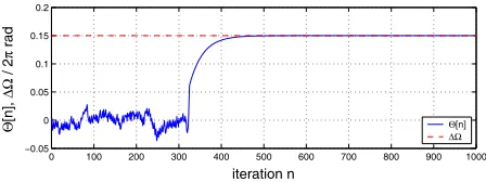
Fig. 4. Learning curve of carrier offset correction according to (31) for GFSK , ,
and .
6.2. Carrier Frequency Offset
Bluetooth permits a carrier offset of up to 75kHz, which can severely degrade performance [4], and for translates into a maxi-mum normalised carrier offset . The matchedÞlter receiver, while performing near-optimum in AWGN, suffers under carrier offset conditions, which is shown in Fig. 3 by the BER curve with carrier offset but no correction. Applying the algorithm derived in Sec. 5 allows to adapt to the correct carrier offset, with the learning curve given in Fig. 4, resulting in a near optimum BER performance of the matchedÞlter according to Fig. 3.
7. CONCLUSION
We have considered high performance matchedÞlter detectors for GFSK modulated signals. By analysing the possible transmitted sequences, a recursive low-cost implementation has been found. For popular transmission schemes such as Bluetooth, where ex-pensive receiver algorithms are prohibitive, the proposed receiver can operate with identical performance but at a considerably re-duced computational cost.
Frequency errors seriously degrade performance of the high-performance receiver. We have proposed a blind adaptation scheme to correct for carrier frequency offset, which are fast converging and permit near optimum receiver performance in AWGN.
8. REFERENCES
[1] W.P. Osborne and M.B. Luntz, “Coherent and Noncoherent De-tection of CPFSK,” IEEE Trans. Comms., COM-22(8):1023–1036, 1974.
[2] T. Aulin, N. Rydbeck, and C.-E.W. Sundberg, “Continuous Phase Modulation-Part II: Partial Response Signaling,” IEEE Trans. Comms, COM-29(3):210–225, 1981.
[3] B.A. Carlson,Communication Systems, McGraw-Hill, 3rd ed., 1986.
[4] C. Robinson and A. Purvis, “Demodulation of Bluetooth GFSK Sig-nals Under Carrier Frequency Error Conditions,” Proc. IEE Col-loq. DSP Enabled Radio, Livingston, UK, Sept. 2003.
[5] A.N.D. Andrea, A. Ginesi, and U. Mengali, “Frequency Detector For CPM,”IEEE Trans. Comms, COM-43(2):1828–1837, 1995.
[6] P. Spasojevic and C.N. Georghiades, “Blind Frequency Compensa-tion For Binary CPM with h=1/2 and A Positive Frequency Pulse,” Proc. Globecom, Sidney, Nov. 1998.
[7] A. Aziz, P. Spasojevic, and C.N. Georghiades, “ Large Frequency Offset Compensation for GMSK Signals: DSP Receiver Implemen-tation,”Proc. Int. Conf. Sig. Proc. Applications, Toronto, June 1998.
[8] T.A. Schonhoff, “Symbol Error Probabilities for M-ary CPFSK: Co-herent and NoncoCo-herent Detection,” IEEE Trans. Comms, COM-24(6):644–652, 1976.
[9] R. Schiphorst, F. Hoeksema, and K. Slump, “Bluetooth Demodula-tion Algorithms and their Performance,” Proc. Workshop Software Radios, Karlsruhe, pp. 99–105, 2002.
[10] Ericsson, Ericsson Bluetooth Development Kit documentation, Oc-tober 1999.