Rochester Institute of Technology
RIT Scholar Works
Theses Thesis/Dissertation Collections
6-1-2009
Volume ray casting techniques and applications
using general purpose computations on graphics
processing units
Michael Romero
Follow this and additional works at:http://scholarworks.rit.edu/theses
This Thesis is brought to you for free and open access by the Thesis/Dissertation Collections at RIT Scholar Works. It has been accepted for inclusion in Theses by an authorized administrator of RIT Scholar Works. For more information, please [email protected].
Recommended Citation
Graphics Processing Units
by
Michael Romero
A Thesis Submitted in Partial Fulfillment of the Requirements for the Degree of Master of Science in Computer Engineering
Supervised by
Professor Dr. Muhammad Shaaban Department of Computer Engineering
Kate Gleason College of Engineering Rochester Institute of Technology
Rochester, New York June 2009
Approved by:
Dr. Muhammad Shaaban
Thesis Advisor, Department of Computer Engineering
Dr. Roy Melton
Committee Member, Department of Computer Engineering
Dr. Joe Geigel
Committee Member, Department of Computer Science
Dr. Reynold Bailey
Thesis Release Permission Form
Rochester Institute of Technology Kate Gleason College of Engineering
Title:
Volume Ray Casting Techniques and Applications using General Purpose Computations on Graphics Processing Units
I, Michael Romero, hereby grant permission to the Wallace Memorial
Library to reproduce my thesis in whole or part.
Michael Romero
Dedication
For my family, for their love and support,
iv
Acknowledgments
I would like to thank my primary advisor Dr. Muhammad Shaaban for
sparking my interest in the field of computer architecture. His instruction
has led to my passion in the field, giving me satisfaction and fulfillment in
my work. Second I would like to thank Dr. Roy Melton for his invaluable
assistance and attention to detail with this thesis. His availability and
guidance have proven very helpful in the course of writing and
development. Next I would like to thank Dr. Joe Geigel for providing
many of the necessary and thought-provoking resources used in the
development of this thesis. His selection of literature has helped shape
many of the concepts explored in this work. Finally I would like to thank
Dr. Reynold Bailey for both his instruction in the field of computer
graphics, and his remarkable dedication towards his students. His
Abstract
Volume Ray Casting Techniques and Applications using General Purpose Computations on Graphics Processing Units
Michael Romero
Traditional 3D computer graphics focus on rendering the exterior of
ob-jects. Volume rendering is a technique used to visualize information
cor-responding to the interior of an object, commonly used in medical
imag-ing and other fields. Visualization of such data may be accomplished by
ray casting; an embarrassingly parallel algorithm also commonly used in
ray tracing. There has been growing interest in performing general purpose
computations on graphics processing units (GPGPU), which are capable
ex-ploiting parallel applications and yielding far greater performance than
se-quential implementations on CPUs. Modern GPUs allow for rapid
accelera-tion of volume rendering applicaaccelera-tions, offering affordable high performance
visualization systems.
This thesis explores volume ray casting performance and visual quality
enhancements using the NVIDIA CUDA platform, and demonstrates how
high quality volume renderings can be produced with interactive and real
time frame rates on modern commodity graphics hardware. A number of
vi
sampling and texture filtering. In a performance comparison of a sequential
versus CUDA implementation on high-end hardware, the latter is capable of
rendering 60 frames per second with an impressive price-performance ratio
heavily favoring GPUs.
A number of unique volume rendering applications are explored
includ-ing multiple volume renderinclud-ing capable of arbitrary placement and rigid
vol-ume registration, hypertexturing and stereoscopic anaglyphs, each greatly
enhanced by the real time interaction of volume data. The techniques and
applications discussed in this thesis may prove to be invaluable tools in
fields such as medical and molecular imaging, flow and scientific
Contents
Dedication . . . iii
Acknowledgments . . . iv
Abstract . . . v
Glossary . . . xviii
1 Introduction. . . 1
2 Motivation . . . 8
2.1 Technology . . . 8
2.2 Applications . . . 11
3 CUDA Background . . . 13
3.1 CUDA Architecture . . . 13
3.1.1 Thread Organization . . . 13
3.1.2 Memory Hierarchy . . . 15
3.1.3 Multiprocessors . . . 17
3.1.4 Compute Model . . . 18
4 Volume Rendering Concepts and Existing Work . . . 21
4.1 Introduction . . . 21
viii
4.2.1 Description . . . 23
4.2.2 Ray Casting Process . . . 23
4.2.3 Shortcomings and Enhancements . . . 26
4.2.4 Early Ray Termination . . . 27
4.2.5 Octree Space Subdivision . . . 28
4.2.6 Empty Space Skipping . . . 28
4.2.7 Supersampling . . . 28
4.3 Slicing Methods . . . 30
4.3.1 Description . . . 30
4.3.2 3D Texturing Process . . . 31
4.3.3 Shortcomings and Enhancements . . . 33
4.4 Analysis of Techniques for CUDA . . . 34
4.5 Existing CUDA Implementations . . . 35
4.5.1 Jusub Kim’s Thesis . . . 36
4.5.2 CUDA SDK Volume Renderer . . . 38
5 Implementation and Features . . . 40
5.1 Volume Rendering Framework . . . 40
5.2 Load Balancing . . . 42
5.3 CUDA Multiprocessor Occupancy . . . 49
5.4 Constant Memory and the World Structure . . . 52
5.5 Texture Memory, Volumes and Filtering . . . 52
5.6 Early Ray Termination . . . 54
5.7 Supersampling . . . 56
5.8 Multiple Volume Rendering . . . 59
5.9 Hypertextures . . . 64
6 Performance Results . . . 68
6.1 Sequential vs. CUDA Implementations . . . 68
6.2 Register Usage . . . 70
6.3 Threads Per Block . . . 73
6.4 Texture Filtering Modes . . . 75
6.5 Early Ray Termination . . . 76
6.6 Supersampling . . . 78
6.7 Voxel Resolution . . . 79
6.8 Number of Volumes . . . 80
6.9 Anaglyph Results . . . 82
7 Analysis . . . 84
7.1 CUDA vs. Sequential Performance . . . 84
7.2 Price vs. Performance . . . 85
7.3 CUDA Object Orientation Difficulties . . . 87
7.4 CUDA Texture Memory Difficulties . . . 88
7.5 Occupancy and Partitioning Analysis . . . 88
7.6 Texture Filtering Analysis . . . 90
7.7 Early Ray Termination Analysis . . . 91
7.8 Supersampling Analysis . . . 93
7.9 Analysis of Volume Characteristics . . . 94
7.10 Anaglyph Analysis . . . 97
8 Thoughts for Investigation and Future Work . . . 100
8.1 Performance . . . 100
8.2 Image Quality . . . 102
8.3 User Interaction . . . 103
x
9 Conclusion . . . 108
Bibliography . . . 110
A Compiling the Volume Renderer . . . 113
B Using the Volume Renderer . . . 114
C Structure of Included CD . . . 116
List of Tables
3.1 Selection of graphics devices and their respective compute
models [10]. . . 19
6.1 A performance comparison in frames per second between
the simple sequential volume renderer and the CUDA
vol-ume renderer. . . 70
6.2 A performance comparison in frames per second between
devices of two different compute models obtained by
vary-ing the register usage of each thread. The number of threads
per block remained a constant 64 threads. . . 71
6.3 A performance comparison in frames per second between
devices of two different compute models obtained by
vary-ing the threads per block. The register usage remained a
constant 32 registers. . . 74
6.4 A performance comparison in frames per second of point
and linear texture filtering modes, across different devices. . 75
6.5 A performance comparison in frames per second of ray march
order and early ray termination, across different devices.
F-to-B indicates front to back ordering, B-to-F indicates back
to front ordering, and a threshold of NA indicates early ray
termination was not enabled. The buckyball volume
xii
6.6 A performance comparison in frames per second of ray march
order and early ray termination, across different devices.
F-to-B indicates front to back ordering, B-to-F indicates back
to front ordering, and a threshold of N/A indicates early ray
termination was not enabled. The sphere testing volume
[13] was used when collecting data. . . 78
6.7 A performance comparison in frames per second of various
degrees of supersampling across different devices. . . 79
6.8 A performance comparison in frames per second of
render-ing volumes with varyrender-ing voxel resolutions across different
devices. Hypertextures were generated with varying voxel
resolutions to collect the data. Note that a 512x512x512
volume could not be rendered using the GeForce 9600m GT
because it exceeds the memory capacity of the device. . . 80
6.9 A performance comparison in frames per second of
render-ing multiple volumes different devices. The buckyball
vol-ume included in the NVIDIA SDK was used when
collect-ing data. Every volume is placed in the center of the scene,
overlapping each other. . . 81
6.10 A performance comparison in frames per second of
render-ing multiple volumes different devices. The buckyball
vol-ume included in the NVIDIA SDK was used when
collect-ing data. The volumes were placed from left to right, bottom
to top in a 8x4 2D grid configuration which can be seen in
6.11 A performance comparison in frames per second of normal
vs. anaglyph rendering methods across different devices.
The engine volume seen in figure 5.17 was used to collect
results. . . 83
7.1 A price-performance comparison between a primitive
se-quential volume rendering implementation running on a CPU
and the CUDA volume rendering implementation running
xiv
List of Figures
1.1 GFLOPS Performance Comparison of Modern GPUs vs.
CPUs. Courtesy of NVIDIA [10]. . . 2
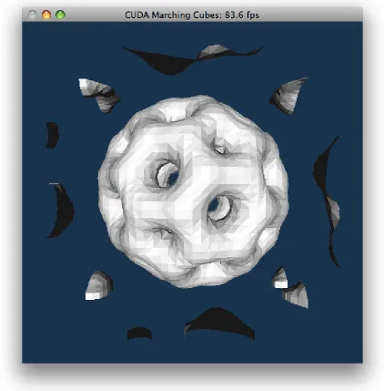
1.2 A buckyball volume rendered as a polygon mesh using the
marching cubes algorithm. This rendering was produced
us-ing the marchus-ing cubes example application in the NVIDIA
CUDA SDK. . . 6
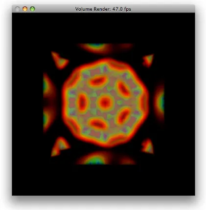
1.3 A buckyball volume rendered using volume ray casting, a
direct volume rendering algorithm. This rendering was
pro-duced using the volume rendering example application in
the NVIDIA CUDA SDK. . . 7
3.1 CUDA Computational Hierarchy. . . 15
3.2 CUDA Memory Hierarchy. . . 17
4.1 The four basic steps of volume ray casting:
(1) Ray Casting: cast a ray from the viewplane.
(2) Sampling: sample the intersected volume along the path
of the ray.
(3) Shading: compute a color value for each voxel based on
a shading model.
(4) Compositing: accumulate color and assign to a pixel on
the viewplane
4.2 Pseudo code of a fragment-program-based volume ray-caster
[15]. . . 24
4.3 The Steps of a Typical Texture-Based Volume Rendering
Implementation [4]. . . 32
4.4 Performance Comparison (CPU v.s. CELL v.s. CUDA) [5]. . 37
5.1 Example of a ray traced scene used to collect partitioning
performance statistics. . . 43
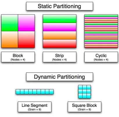
5.2 Static and Dynamic Thread Partitioning Methods. . . 45
5.3 Performance of Static and Dynamic Partitioning Methods. . 46
5.4 Actual partitioning of threads in the volume renderer. The
blue channel is increased based on the thread ID within a
block, and the red channel is increased based on the block
ID within a grid. This shows dynamic partitioning of line
segments of a grain size equal to the threads per block; in
this case, 64. . . 48
5.5 An image of a 32x32x32 hypertexture rendered using point
filtering (left) and linear filtering (right). . . 54
5.6 Pseudocode used to accumulate color by ray marching through
a volume from front to back. . . 55
5.7 Pseudocode used to accumulate color by ray marching through
a volume from back to front. . . 55
5.8 Four images showing a hypertexture rendered in back to
front order (top left), front to back order (top right), front
to back order with an early ray termination threshold of 0.5
(bottom left) and front to back order with an early ray
xvi
5.9 Four images showing a simulated Buckyball rendered using
point filtering with no supersampling (top left), point
filter-ing with 16x supersamplfilter-ing (top right), linear filterfilter-ing with
no supersampling (bottom left) and linear filtering with 16x
supersampling (bottom right). . . 58
5.10 Pseudocode for supersampling. . . 59
5.11 An image showing six volumes rendered simultaneously.
From left to right, top to bottom they are a protein molecule,
an engine block a hypertexture, an orange, a monkey’s skill
and a frog. . . 60
5.12 An image showing 32 individual volumes, the current
max-imum number of displayable volumes in the renderer. . . 62
5.13 An image showing an MRI scan (left) and a CT scan (right)
of a monkey’s head. The density factor of the MRI scan is
one fifth the density factor of the CT scan. . . 63
5.14 An image showing an MRI scan and the CT scan of a
mon-key’s head nested together. The density factor of the MRI
scan is one fifth the density factor of the CT scan to
high-light the results of the CT scan. . . 64
5.15 Two images showing the density modulation function of
a hypertexture. The image to the left was generated with
voxel values between [0,1]. The image to the right was
gen-erated using voxel values between [-0.5,0.5], and
reinter-preted as unsigned values. . . 65
5.17 An image showing a stereoscopic anaglyph of an engine
block. To properly view the image, it must be reproduced in
color, and the observer requires “3D glasses” with red and
cyan lenses. . . 67
6.1 Renderings of a 32x32x32 hypertexture from the simple
se-quential volume renderer (left) and the CUDA volume
ren-derer (right). . . 69
6.2 Charts produced by the CUDA Occupancy Calculator
show-ing occupancy by varyshow-ing the register usage for a compute
model 1.1 device. . . 72
6.3 Charts produced by the CUDA Occupancy Calculator
show-ing occupancy by varyshow-ing the register usage for a compute
model 1.3 device. . . 73
6.4 Images of the two models used for gathering performance
results for early ray termination. The images are of a
Buck-yball (left) and a Sphere distance field (right). . . 77
7.1 A graph of the results showing how performance scales with
xviii
Glossary
block
A grouping of threads dynamically allocated to the next available
mul-tiprocessor. 15
GPGPU
General-Purpose computing on Graphics Processing Units. 1
grain size
The amount of work dynamically partitioned among multiprocessors,
synonymous with threads per block. 47
grid
A collection of thread blocks executing the same kernel. 15
kernel
The code that each thread executes on the graphics device, the entry
point for computation on the device. 14
multiprocessor
A cluster of computational resources on the graphics device. There
multiprocessor occupancy
The ratio of the number of active warps on a multiprocessor to the
max-imum number of active warps. Determined by devices compute model,
threads per block, registers per thread and shared memory usage. 50
ray casting
An embarrassingly algorithm for direct volume rendering. 23
thread
The most fundamental level of the CUDA computational hierarchy,
where several perform computations in parallel. 15
transfer function
A function used to corollate a density with a color and opacity. 34
voxel
Discrete volume element, like a three dimensional pixel. 3
warp
A group of 32 threads from the same thread block starting at the same
1
Chapter 1
Introduction
Technology trends and advances in graphics techniques (such as those found
in modern video games and simulations) have led to a need for extremely
powerful dedicated computational hardware to perform the necessary
calcu-lations. Graphics hardware companies such as AMD/ATI and NVIDIA have
developed graphics processors capable of massively parallel processing,
with large throughput and memory bandwidth typically necessary for
dis-playing high resolution graphics. However, these hardware devices have the
potential to be repurposed and used for other non-graphics-related work, or
programmed outside the bounds of traditional graphics APIs. This is
com-monly refered to as “GPGPU,” or “General-purpose computing on graphics
processing units.” A number of frameworks allows for graphics devices
to be repurposed and programmed in a general fashion, such as Stanford’s
Brook programming language, AMD’s CTM (Close To Metal) technology,
and NVIDIA’s programming interface known as CUDA (Compute Unified
Device Architecture). Utilizing graphics devices to execute massively
paral-lel algorithms will yield a significantly large speedup over sequential
performance computing nodes. Figure 1.1 illustrates the potential
compu-tational throughput of NVIDIA’s discrete graphics devices in contrast with
[image:22.612.101.489.178.448.2]CPU offerings from Intel.
Figure 1.1: GFLOPS Performance Comparison of Modern GPUs vs. CPUs. Courtesy of NVIDIA [10].
With the expanded capabilities of graphics processors that programming
frameworks like CUDA afford, it is possible to achieve performance that
has previously been out of reach. Real-time or interactive manipulation of
data is a common use of these technologies, which is often beneficial to the
exploration and understanding of these particular data sets. Many
3
by these applications must be parallelizable; ideally, embarrassingly
paral-lel. Target applications include audio and video processing, physics
simu-lations, flow dynamics, digital signal processing, computer vision, weather
modeling, neural networks, medical imaging and many more. In the case
of medical imaging, it is desirable to reconstruct models obtained from CT
(computed tomography) scans, and view the results. The data obtained from
a CT scan is “voxel” data, and requires a certain rendering technique in
or-der to view and interpret the results.
Volume rendering describes a specific paradigm of visualizing
three-dimensional data. A 3D model is typically constructed from a polygon
mesh which defines only the surface of the model. With volume
render-ing however, the data describrender-ing the model defines the interior volume of
the model as well, so the internal details of a 3D object may be assigned
“optical properties” such as color and opacity. Volumetric data is comprised
of “voxels” or volume elements, and can be viewed a number of ways. One
option is to approximate and render a polygon mesh from the voxel data.
One of the most common approximation methods is the “marching cubes”
algorithm. This algorithm and other approximation algorithms allow the
vi-sualization of the approximate surface structure of a volume, however they
do not allow visualization of the volume’s interior, and are not suitable for
the purposes of this thesis. Direct volume rendering allows the visualization
optical properties to each voxel element in the scene. Direct volume
render-ing can be achieved by a number of techniques includrender-ing volume ray castrender-ing
[15] or plane composing algorithms such as texture-based rendering [4] or
shear-warping [7]. Additionally, various optimization and quality
enhance-ment techniques exist, such as early ray termination, volume segenhance-mentation,
empty space skipping, anti-aliasing, interpolation of voxel data,
illumina-tion models and more. Figure 1.2 shows an approximated volume
render-ing of a buckyball represented as a polygon mesh by usrender-ing the marchrender-ing
cubes algorithm. Figure 1.3 shows a direct volume rendering of a buckyball
achieved using the ray casting algorithm. Comparing these two images, it is
clear that more information can be gleaned by assigning color and opacity to
the density of the volume and visualizing the volumes interior than strictly
visualizing the approximated surface of the volume.
This thesis focuses on implementing direct volume rendering techniques
using commodity graphics cards, specifically the volume ray casting
ap-proach, though other approaches may benefit from the results of this work.
NVIDIA’s CUDA was chosen as the target GPGPU platform, and this
docu-ment will discuss the approach to impledocu-menting a volume ray casting system
using this platform, the advantages and speedups obtained, as well as
diffi-culties encountered. This work’s unique contributions lie in the
implemen-tation of some of the visual and performance enhancements on the CUDA
platform, development of an extensible and easily manageable framework
5
applications made possible by these enhancements such as the interactive
rendering of multiple volumes and stereoscopic anaglyphs. The volume ray
casting software, all of the effects achieved, and applications demonstrated
are capable of running with interactive performance on commodity off the
shelf devices, including laptops, and across Microsoft Windows and Mac
OS X operating systems.
This thesis has been organized to best place the volume rendering system
developed in context. Chapter 2 discusses the motivation behind volume
rendering, and possible applications of this rendering technique. Chapter 3
provides the necessary background information to understand how CUDA
may be used to exploit volume rendering algorithms. Chapter 4 examines
common volume rendering concepts, the existing efforts in the field, and
the potential that exists to improve on these efforts. Chapter 5 describes the
implementation details, features and novel contributions of the volume
ren-dering system developed. Chapter 6 shows the performance characteristics
of the volume renderer by listing the framerate of the system while
vary-ing a number of factors. Chapter 7 analyzes the quality, performance and
effectiveness of each applicable volume rendering technique or application.
Chapter 8 contains ideas and considerations for the future of the system
de-veloped in this thesis and volume rendering in general. Finally, chapter 9
7
Chapter 2
Motivation
To place the volume rendering efforts of this thesis in the proper context,
it is necessary to examine the technologies available capable of
perform-ing volume renderperform-ing, and the potential applications for volume renderperform-ing.
When the potential applications are considered, ideal technologies for these
applications may be identified.
2.1
Technology
In most common modern day implementations of visualizing three-dimensional
models on a computer, a polygon consisting of a mesh of triangles is used to
represent the figure to be displayed. This polygon mesh describes the
sur-face of the model, and various techniques and special effects are applied to
add detail and light to a scene described by polygons. Volumetric rendering
differs from traditional visualization technique by using a 3D model
rep-resented by “voxel” or “volumetric elements” rather than a polygon mesh.
Voxel representations describe a 3D model as a set of values on a regular
9
space, and these voxels describe the interior as well as exterior surface of
the model. This differs from polygon meshes, where the mesh describes a
series of points on the surface of the model but not the interior of the model.
This fundamental difference is one of the primary advantages of volumetric
rendering over traditional rendering schemes: voxel-based models contain
information about their volume.
Current generation specialized graphics hardware is targeted specifically
for rendering polygon meshes, and the performance is more than adequate
to render scenes interactively in real-time. Volume rendering systems exist
in a variety of fields. Particular interest in volume rendering comes from
the medical imaging field, because body scans obtained from patients are
volumetric in nature, and it is very desirable to investigate these body scans
interactively. Volume rendering systems have also been used in a
num-ber of video games for their ability to render complex terrain. These
sys-tems have historically done all the necessary rendering work on the CPU.
However, the common consumer-level graphics hardware offerings from
NVIDIA and AMD/ATI do not targeting volume rendering. Advances in
graphics hardware have ignored volumetric rendering, and the necessary
performance to render large voxel-based data sets with a high level of
de-tail interactively has been very difficult or impossible to achieve.
Fortu-nately dedicated consumer-level graphics hardware has been identified for
its massively parallel computational abilities. With the introduction of
utilized for volume rendering acceleration [6]. Furthermore, graphics
hard-ware companies are now releasing APIs and frameworks which expose the
architecture of these devices for general purpose programming. Currently,
the most popular and prevalent API is NVIDIA’s CUDA platform, which
stands for “Compute Unified Device Architecture.” This platform allows
for the programming of any CUDA capable device to perform general
pur-pose computations in parallel.
This thesis implements a system capable of rendering and interacting
with volumetric data sets by programming graphics hardware to perform
the general purpose computations necessary for volume rendering. This
is known as General Purpose computation on Graphics Processing Units
(GPGPU). The target platform is NVIDIA’s CUDA, but the general C/C++
ray casting parallel algorithm should also be adaptable to other dedicated
graphics hardware, such as the offerings from AMD/ATI, Intel, or SGI. The
volume renderer demonstrates a large improvement in performance and at
a high level of detail over rendering using a CPU. The system is capable of
interactively rendering relatively large data sets, larger and more complex
than those which can be rendered interactively on the CPU. Furthermore,
this thesis also demonstrate a number of applications of volume-based
ren-dering; specifically the rendering of hypertextures, multiple volumes, and
11
2.2
Applications
Several applications exist which would benefit from an interactive volume
rendering system, such as medical imaging applications. Common body
scans such as CT and MRI scans generate images of several “slices” of a
patient’s body. These slices may be reassembled into voxel data. Using the
system developed in this thesis, this data set may be displayed and explored
interactively by doctors or surgeons. Furthermore, the volume rendering
system developed here allows for multiple volumes to be positioned in the
same space, performing a type of rigid registration. This would allow
doc-tors to gain new insight on patients by exploring multiple medical scans
simultaneously.
While the possibility of rendering static volumetric data interactively has
many applications, the ability to deform these data sets opens the way to
many more possibilities. Current 3D modeling systems operate by
plac-ing vertices and exportplac-ing meshes based on those vertices. With volumetric
data, a 3D model could instead be created by “sculpting” the model.
Sim-ilar to the way popular image editing tools provide brushes to paint with,
and blending tools to smooth edges, a voxel painting system could provide
cube or sphere brushes as an extension to constructive solid geometry, and
smoothing functions to round or blend together 3D models. In the case of
medical images, surgeons could use the volumetric representation of a
cutting, bending, pinching and suturing of a completely virtual body;
some-thing that has not yet been efficiently demonstrated.
Voxels have been used in computer games and simulations to define
com-plex terrain geometry in lieu of another popular technique known as “height
maps.” Height maps are gray scale images where the light and dark spots
are converted into peaks and valleys in terrain. The shortcoming is that
height maps do not support concave structures. Voxels offer a solution to
this problem, providing the additional information.
In computer simulations and gaming, volumetric data could provide much
higher levels of detail and realism for certain objects. Much like the
ad-vancements ray tracing brings to lighting, volume rendering could provide
similar advancements to geometry. Deformable volumes would allow a
player to alter the environment without pre-computed demolition models.
For example, using a physics system, it would be possible to blow up walls,
dent trash cans, or shatter glass, and perform these actions on anything in a
scene without the need to pre-program a model’s reaction to certain
behav-ior.
It would also be possible to interact with volumes in ways typically
re-served for other media. For example, stereoscopic visualization is becoming
more prevalent in video games and motion pictures. Volumes can also be
visualized using stereoscopy. This thesis provides a system for rendering
13
Chapter 3
CUDA Background
Background information on NVIDIA’s CUDA platform is described here. A
fundamental understanding of CUDA is necessary to understand how
vol-ume rendering algorithms may be exploited by its architecture.
3.1
CUDA Architecture
The CUDA programming guides [9], [10] provided by NVIDIA
Corpora-tion document the architecture of the CUDA framework and runtime, the
CUDA programming paradigm, and list several performance considerations
when programming for CUDA. The following summarizes the CUDA
ar-chitecture in terms of thread organization, memory hierarchy, processing
elements and compute models.
3.1.1 Thread Organization
In the CUDA processing paradigm (as well as other paradigms similar to
stream processing) there is a notion of a “kernel.” A kernel is essentially a
mini-program or subroutine. Kernels are the parallel programs to be run on
of primitive “threads” simultaneously execute a kernel program. Batches of
these primitive threads are organized into “thread blocks.” A thread block
contains a specific number of primitive threads, chosen based on the amount
of available shared memory, as well as the memory access latency hiding
characteristics desired. The number of threads in a thread block is also
limited by the architecture to a total of 512 threads per block. Each thread
within a thread block can communicate efficiently using the shared memory
allocated to each thread block. Using this shared memory, all threads can
also sync within a thread block. Every thread within a thread block has its
own thread ID. Thread blocks are conceptually organized into 1D, 2D or 3D
arrays of threads for convenience.
A “grid” is a collection of thread blocks of the same thread
dimensional-ity which all execute the same kernel. Grids are useful for computing a large
number of threads in parallel since thread blocks are physically limited to
only 512 threads per block. However, thread blocks within a grid may not
communicate via shared memory, and consequently may not synchronize
with one another.
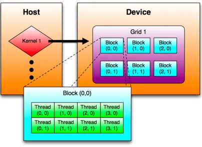
Figure 3.1 demonstrates the thread hierarchy described. Here, kernel 1
contains a 3x2 grid of thread blocks. Each thread block is a 5x3 block of
threads, for a total of 90 threads in kernel 1. Kernel 2 may contain a different
organization of thread blocks, which in turn may contain an array of threads
15
Figure 3.1: CUDA Computational Hierarchy.
3.1.2 Memory Hierarchy
There are several levels of memory on the GPU device, each with distinct
read and write characteristics. Every primitive thread has access to private
“local memory” as well as registers. This “local memory” is really a
mis-nomer; the memory is private to the thread, but is not stored local to the
thread’s registers; instead it is located off-chip in the global GDDR memory
available on the graphics card. Every thread in a thread block also has access
to a unified “shared memory,” shared among all threads for the life of that
which is located off-chip on the main GDDR memory module, which
there-fore has the largest capacity but is the most costly to interact with. There
also exists read-only “constant memory” and “texture memory”, in the same
location as the global memory.
The global, constant and texture memory are optimized for different
memory usage models. Global memory is not cached, though memory
transactions may be coalesced to hide the high memory access latency.
These coalescence rules and behaviors are dependent on the particular
de-vice used. The read-only constant memory resides in the same location as
global memory, but this memory may be cached. On a cache hit, regardless
of the number of threads reading, the access time is that of a register access
for each address being read. The read-only texture memory also resides in
the same location as global memory and is also cached. Texture memory
differs from constant memory in that its caching policy specifically exploits
2D spatial locality. This is due to the use of “textures” in 3D graphics:
the use of 2D images to texture the surface of 3D polygons. Textures are
frequently read and benefit from caching the texture spatially.
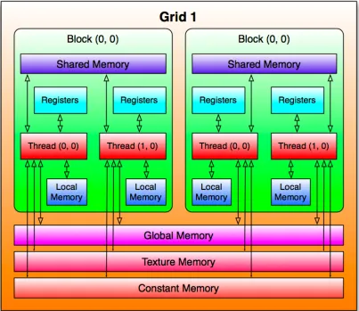
Figure 3.2 shows the scope of each of the memory segments in the CUDA
memory hierarchy. Registers and local memory are unique to a thread,
shared memory is unique to a block, and global, constant, and texture
mem-ories exist across all blocks. It’s important to note that local memory has the
17
Figure 3.2: CUDA Memory Hierarchy.
3.1.3 Multiprocessors
CUDA capable GPUs are constructed with the Tesla architecture. CUDA
applications may be run on any card which supports this architecture, but
each GPU device may have different specifications and therefore a slightly
different set of supported features and a different number of available
on a “multiprocessor.” This multiprocessor contains the resources to
sup-port a certain number of threads.
•8 Scalar Processor cores
•2 special function units for transcendentals
•1 multithreaded instruction unit
•On-chip shared memory
One or more thread blocks are assigned to a multiprocessor during the
execution of a kernel. The CUDA runtime handles the dynamic
schedul-ing of thread blocks on a group of multiprocessors. The scheduler only
assigns a thread block to a multiprocessor when enough resources are
avail-able to support the thread block. Each block is split into SIMD
(Single-Instruction Multiple-Data) groups of threads called “warps.” The SIMD
unit creates, manages, schedules and executes 32 threads simultaneously to
create a warp. Every warp is synchronous, and therefore care must be taken
to ensure that certain threads within a warp do not take substantially longer
than other threads in that same warp, because the warp only executes as fast
as the slowest thread. There are a number of programming hints provided
in the CUDA programming guide to help prevent such warp divergence.
3.1.4 Compute Model
Every CUDA-enabled device has a compute capability number. This
num-ber indicates a standard numnum-ber of registers, memory size, etc. for all
19
compatible. The CUDA Programming Guide [10] available from NVIDIA
details the compute capabilities of various graphics devices, an excerpt from
which can be found in figure 3.1.
Num Multiprocessors Compute Capability
Tesla C870 16 1.0
GeForce 9600m GT 2 1.1
GeForce 9800GT 14 1.1
[image:39.612.130.487.196.272.2]GeForce GTX260 24 1.3
Table 3.1: Selection of graphics devices and their respective compute models [10].
The primary devices used for the development of this thesis are the GeForce
9600m GT, a discrete graphics card found in mid-high range laptops, and
the GTX260, a graphics card found in mid-high range gaming desktops. At
the time of writing, the GTX200 series conforms to the most recent
com-pute model. This latest comcom-pute model, 1.3, has a number of significant
improvements over previous compute models, including the following.
•Double precision support
•Higher memory bandwidth
•Double the number of available registers
The double precision floating point support is a feature not often used in
computer graphics, but is frequently used in various scientific and
engineer-ing calculations, which may performed usengineer-ing CUDA. The higher memory
bandwidth decreases transfer times between the host and the device.
greater multiprocessor occupancy, resulting in higher computational
21
Chapter 4
Volume Rendering Concepts and
Existing Work
This chapter outlines several fundamental volume rendering concepts and
references the various academic publications in which they are discussed.
A brief analysis of the rendering techniques is made, and their suitability
for implementation on the CUDA platform is also considered. Finally this
chapter takes survey of existing CUDA volume rendering implementations.
4.1
Introduction
There are two primary categories of algorithms associated with direct
vol-ume rendering. The first, ray casting algorithms, operate by casting a ray
down the line of sight for every pixel in the image of the scene. Each ray
assigns a color value to a pixel by compositing the color and transparency
of the voxels in the volumetric model intersected by each respective ray.
Ray casting algorithms may use early ray termination [14], as well as
oc-tree subdivision [8] and empty space skipping [6] to reduce computational
complexity is relative to the image size times the depth of the volume [2].
Plane composing algorithms are the other main category of direct
vol-ume rendering algorithms. These algorithms operate by compositing several
slices which comprise a volumetric model. These algorithms tend to work
best when the view-plane is fixed parallel to the model, so that each of the
voxels being composed may be accessed on separate planes. Texture-based
rendering is one key technique which composites slices of volumetric data.
Shear-Warp factorization can be used to enhance performance of rendering
volume slices by applying a shearing transformation to exploit spatial
co-herency of the model, reducing computational complexity of rendering a
volume from an arbitrary viewing angle [7]. The computational complexity
is relative to the volume size [2].
The following is a brief overview of the various rendering techniques,
and comparisons of their advantages and shortcomings, such as
compu-tational complexity, required memory capacity, and visual quality. These
techniques will be used to identify the most suitable category of techniques
to target for enhancements, as well as to provide a relative comparison of
23
4.2
Ray Casting
4.2.1 Description
One primary technique for rendering volumes is known as “ray casting.”
Ray casting is an object order rendering technique, where the computations
are performed based on the voxels in the volumetric model intersected by
each ray. Ray casting has been overlooked as a primary volume
render-ing algorithm in favor of slicrender-ing methods, in part because the advances in
graphic acceleration hardware brought optimized texturing units capable of
greatly enhancing the performance of 3D texture-based rendering methods.
However, more recent trends in hardware graphics acceleration have given
way to CUDA (as well as other GPGPU platforms), putting the performance
of ray casting methods on par with other slicing methods and reaffirming
ray casting as a worthwhile volume rendering effort. Figure 1.3 shows an
example rendering of a ray casted volume.
4.2.2 Ray Casting Process
The general ray casting procedure is similar for most volume ray casting
systems. For each pixel in a resulting image, a single ray is cast through the
scene, intersecting with the volumes to be rendered. These rays may be cast
independently, resulting in full pixel-parallelism. Each voxel intersected
with the ray has a certain color and opacity. Shading can be applied based
that is a function of color and opacity for each voxel the ray intersects, and
renders a pixel. This approach fits well into a parallel stream processing
paradigm, exhibited by fragment processors, as well as the CUDA
archi-tecture. Figure 4.1 shows a graphical representation of the basic ray casting
procedure. Figure 4.2 details the pseudo code for a fragment-program-based
implementation of a volume ray-caster, described by S. Stegmaier et al.for
a volume rendering framework [15].
Figure 4.1: The four basic steps of volume ray casting: (1) Ray Casting: cast a ray from the viewplane.
(2) Sampling: sample the intersected volume along the path of the ray. (3) Shading: compute a color value for each voxel based on a shading model. (4) Compositing: accumulate color and assign to a pixel on the viewplane Courtesy of Wikipedia [17].
Compute volume entry position
Compute ray of sight direction
While in volume
Lookup data value at ray position Accumulate color and opacity
Advance along ray
25
A great deal of emphasis has been placed on fitting the ray casting
pro-cess into a stream propro-cessing system. Stream propro-cessing is essentially a
sys-tem where chain of microprocessing units perform simple “kernels” (small
programs or subroutines), with one microprocessor’s output feeding directly
to the input of the next. The advantage to stream processing coincide with
the advantages of pipelining, by splitting the work into stages and feeding
the pipeline in a specific interval, so that the pipeline produces a final
re-sult every interval. Stream processing takes this concept further by having a
data “stream” run through several kernels, with dedicated hardware (and
of-ten scratchpad memory) for each kernel performed, without the overhead of
context switching one subroutine to another. This offers very high
through-put of a complex series of operations. Modern graphics hardware performs
this kind of stream processing in SIMD fashion, where several data-parallel
homogeneous streams may be computed with each instruction.
In its relation to ray casting, initial efforts spawned from Purcell’s
publi-cation of a ray tracing technique that took advantage of the stream
process-ing paradigm of modern graphics hardware [12]. Followprocess-ing this publication,
one of the most ground-breaking volume ray casting papers was published
by Kruger and Westermann, where a ray casting approach that uses multiple
passes over the scene (for early ray termination) to render an image using
shader model 2.0 was described [6]. A volume rendering framework was
finally described by S. Stegmaier et al., which requires only one pass by
The author of the pseudo code in figure 4.2 envisioned using a 3D
tex-ture for the lookup of the raw data used to accumulate color and opacity
information. 3D textures are described in section 4.3.1 of this document.
In the CUDA architecture, texture memory exhibits the most desirable
stor-age and access properties in a system. Texture memory is located in main
memory on the device, and therefore has the largest capacity on the device
(exact size dependent on the specific hardware device). Texture memory
is constant and is optimized for data exhibiting 2D spatial locality through
its caching system [10]. Considering its capacity and caching properties,
texture memory is a prime target for volumetric data storage.
4.2.3 Shortcomings and Enhancements
Ray casting algorithms have historically required multiple passes to render
a scene [6], resulting in long rendering times when compared with other
slicing-based methods. Although a single-pass implementation of the ray
casting algorithm has been recently discussed [15], this approach requires
support for dynamic flow control within the data streams. While NVIDIA’s
CUDA platform is capable of performing dynamic flow control, it requires
significant effort to implement efficiently, and often results in a performance
hit.
Due to the relatively lengthy rendering time involved with ray casting, a
number of performance enhancements have been identified to speed up the
27
skipping are all methods employed to reduce the degree of computations
that must be performed on each ray, leading to quicker renderings. In
addi-tion to the various performance enhancements for volume ray casting, there
are also image quality enhancement techniques such as supersampling.
4.2.4 Early Ray Termination
Early ray termination can be performed when a volume is rendered in
front-to-back order (as opposed to back-to-front order). This typically requires
multiple passes through the volume to extract the necessary information
about the front and back faces. If a ray leaves the volume being traced, the
ray terminates and no more computations are performed. Furthermore, this
technique employs a threshold value, indicating a maximum opacity/density.
As a ray progresses and opacity and color is accumulated, the resulting
com-posited value is checked against the threshold. If the integrated opacity
reaches approximately 1 (within the threshold), it is decided that the
re-maining voxels along the ray will not significantly contribute to the color
of the pixel being rendered, and the ray will terminate [14]. This early
ter-mination enhancement efficiently reduces the degree of computation while
4.2.5 Octree Space Subdivision
Octrees are a tree structure commonly employed when dealing with 3D
graphics. In an octree, each parent node may contain either zero or 8
chil-dren. The 8 children achieve a 2x2x2 regular subdivision of the parent node,
essentially dividing each node into 8 equal parts, or “leaves” [8]. The
subdi-vision of space by the octree is simply a very convenient hierarchical
index-ing mechanism, which is commonly used when performindex-ing occlusion. In
volumetric rendering applications, octrees are used to perform empty space
skipping.
4.2.6 Empty Space Skipping
Empty space skipping is a technique that allows a ray, when cast through
a volume, to “jump” through areas of empty space by avoiding sampling
along the ray as long as the ray is intersecting with empty space. This
tech-nique requires a separate data structure to contain the empty space
infor-mation [6]. Octrees are often used to store the statistical inforinfor-mation on
the child nodes within the tree, such as the min/max bounds for the region
covered by the node, providing the requisite information to perform space
skipping.
4.2.7 Supersampling
Supersampling or oversampling in general is the act of sampling the scene at
29
is calculated by sampling multiple times per pixel. The goal of
supersam-pling is to combat artifacts and aliasing caused by the coarse granularity of
per-pixel sampling. The approach is to sample within a pixel region multiple
times and average the color values returned from each of those samples to
obtain the best possible color representation for a given pixel. The specific
qualities of an image have been identified as causing noticeable artifacts
due to aliasing, most notably, abrupt changes in intensity commonly found
along the silhouette edge of an object in the scene [1]. Adaptive approaches
involving convolution have been used to target these areas of high-contrast
in an image and perform supersampling on these key points.
A number of supersampling distribution techniques exist, most with their
own positive and negative aspects. Some selected examples of sampling
techniques include “Regular” sampling, “Jittered” sampling, “n-Rooks”
sam-pling, “Multi-Jittered” sampling and “Hammersley” sampling. Each of these
techniques is detailed in chapter 5 of [16]. This chapter includes code
list-ings and excellent figures detailing the effects of each sampling technique.
Furthermore, the chapter identifies three characteristics of a well-distributed
2D sampling pattern: the samples are uniformly distributed on a 2D unit
square, projecting the points in the x- and y-directions yields a uniformly
distributed 1D projection, and finally there must be a minimum distance
between samples. Of the examples mentioned here and in [16], only
Ham-mersley sampling exhibits all these characteristics, but is still less than ideal.
between sample points in the x-and y-direction can result in aliasing.
Ham-mersley samples are regularly spaced in the x- and y-directions.
4.3
Slicing Methods
4.3.1 Description
Direct rendering of a volume can be achieved on modern dedicated graphics
cards using a three dimensional texture. A “texture”, in the field of computer
graphics, is an image typically applied to the surface of some geometry in
order to simulate the details and appearance of the surface of that geometry.
A texture in this sense is two dimensional. A 3D texture can be achieved
us-ing a stack of 2D texture slices, which is capable of texturus-ing the volume of
an object. Other 3D texture objects exist in hardware specially designed to
deal with 3D textures. Historically, 3D texture mapping systems were used
by a number of companies in their graphics workstations, such as Silicon
Graphics and their InfiniteReality system. Many modern graphics hardware
devices support 3D Texture Objects.
3D Texturing is an image order rendering technique, meaning
computa-tions are performed based on image size and not based on the number of
objects in the scene. Typically, there are a far greater number of pixels in
a scene than the number of geometric primitives, making most object-order
techniques quicker than image-order rendering techniques. However, in the
31
of the image to be rendered, making the image-order techniques more
effi-cient in most situations. It is generally accepted that, given that nearly all
modern graphics hardware supports 3D texture acceleration, real-time
in-teractive rendering of reasonably sized volumes may be achieved using this
technique [6].
4.3.2 3D Texturing Process
The “optical properties” of the given volume, specified by an “optical model”
(a model which relates the available volume data, typically density, to
opti-cal properties such as the emission and absorption of light) can be defined by
either using data values directly, or by a “transfer function.” Simple
trans-fer functions may be implemented using a fragment shader, but typically a
texture lookup table is used [4].
The sampling and compositing of texture-based volume rendering
sys-tems are typically performed in a series of steps identified in “Volume
Ren-dering Techniques” [4]. The GPUGems books are compilations of advanced
rendering techniques, and are copyrighted by NVIDIA corporation. First,
a series of 2D geometric primitives (proxy polygons perpendicular to the
viewing direction, parallel to the viewing plane) is placed within the
vol-ume. Each of these primitives is assigned coordinates to sample from within
the 3D texture. The proxy geometry is then rasterized, such that each proxy
polygon is rasterized with its respective 2D slice of the 3D texture. The
the transfer function textures to assign the optical properties to the volume.
Various illumination techniques such as shading may also be applied before
the textures are finally composited.
A texture-based volume rendering implementation typically contains three
primary steps. Figure 4.3 demonstrates these steps. These are initialize,
up-date and draw. Initialize is usually performed only once, while the upup-date
and draw routines are executed when user input is received, and the scene
must be redrawn, for example when the camera changes position or
orien-tation.
Figure 4.3: The Steps of a Typical Texture-Based Volume Rendering Implementation [4].
The initialization routine prepares the data and shader routines to be used
in the volume rendering process. The volume data must be compressed and
downloaded to main memory on the graphics device. Before sending the
volume data, it may first undergo a variety of processing stages, such as the
computation of gradients or downsampling of the data. The initialization
stage is also responsible for the construction of the transfer function lookup
33
The next step is to update the scene. This step occurs every time user
input is received which changes any properties of the scene being rendered,
or the viewpoint from which the scene is viewed. The proxy geometry is
computed in this stage, with a number of slices through the volume being
computed, and stored in vertex arrays. Vertices are computed by
intersect-ing planes with the volume boundintersect-ing box (perpendicular to the viewintersect-ing
angle), and sorting the resulting vertices either clockwise or counter
clock-wise around their center. For each vertex, the corresponding 3D texture
coordinate is calculated. [4].
4.3.3 Shortcomings and Enhancements
Slicing techniques have historically been much faster than ray casting
tech-niques, but most recently the performance gap has closed and these
algo-rithms no longer have such a large performance advantage. Now that the
performance gap is closing, the performance versus quality trade off is
be-coming unbalanced, and images obtained by slicing approaches are of lower
quality than those rendered by ray casting. Slice-based techniques lead to
artifacts due to aliasing and cannot easily model viewing rays which change
direction, as exhibited by refracting volumes [15]. It is also difficult for
slice-based methods to implement more complicated optical models,
com-pared to the ease of implementation of the same optical models using a ray
casting method. These quality issues have been addressed by the use of over
A number of performance enhancements have been proposed for the
var-ious shortcomings of the 3D texturing approach by integrating specific ray
casting techniques with slice-based approaches. It has been observed that
in the standard implementation of 3D texturing, a number of unnecessary
operations are performed (such as texture fetch operations, numerical
oper-ations, and per pixel blending operations) are performed on fragments that
do not contribute to the final image. Therefore, it was proposed that
accel-eration techniques such as early ray termination and empty-space skipping
be integrated into 3D texturing approaches [6].
For reference, the following are extensions or enhancements to the
slic-ing approach.
•Shear-Warp Factorization [7]
•Volumetric Clipping [14]
•Pre-Integration [14]
•Integration of Ray Casting Techniques [6]
4.4
Analysis of Techniques for CUDA
The ray casting algorithm is embarrassingly parallel, making it an ideal
tar-get for implementation on CUDA. Despite the dynamic branching inherent
in the ray casting algorithm, the algorithm is much easier to exploit using
CUDA than the slicing method. The ray casting approach also has the
35
to aliasing, as well as more potential illumination models. Several
perfor-mance enhancements have been identified and listed for ray casting such as
early ray termination, octree subdivision and empty space skipping. Each
of these performance enhancements may be implemented using CUDA. As
discussed, the storage of volume data may also be exploited using CUDA by
placing it in texture memory. Texture memory exhibits a caching policy that
exploits spatial locality; ideal for accessing volume data. The ray casting
approach was chosen for implementation for this thesis due to its parallel
and easily exploitable nature, as well as the ease of implementation of the
standard performance and quality enhancements.
4.5
Existing CUDA Implementations
A small number of efforts to perform volume ray casting using CUDA exist.
However, most of these efforts are non-academic in nature, and are closed
source projects still in development. The most relevant volume ray casting
effort was discovered on NVIDIA’s CUDA website. A recent doctoral thesis
released in May 2008 by Jusub Kim at the University of Maryland, College
Park, focuses on volume ray casting using the CUDA platform, as well as
the CELL Broadband Engine [5]. A second relevant volume ray casting
on CUDA system which deserves mention is an example volume rendering
4.5.1 Jusub Kim’s Thesis
Kim’s doctoral thesis makes a number of advancements in ray casting on
the CUDA platform and the CELL Broadband Engine [5]. First, new
out-of-core data management techniques were implemented; specifically a new
layout scheme of the slice data used to compose the volume and a new
mul-tidimensional indexing structure. Second, an efficient stream-based
paral-lel implementation of volume ray casting was implemented on the CELL
processor and then extended to the CUDA platform. This implementation
specifically optimized two of the primary ray casting performance
tech-niques, early ray termination and empty space skipping.
The results of Kim’s CUDA implementation show CUDA as the clear
champion of the three architectures assessed (NVIDIA’s CUDA on an 8800GTX,
IBM’s CELL processor and Intel’s Xeon processor). The CUDA
implemen-tation achieved a 1.5x speedup over the CELL, and a 15x speedup over the
Xeon processor, with only a third of the lines of code used for the CELL
processor’s implementation. Figure 4.4 shows a performance comparison
in frames per second (fps) of four different volumes on the three
architec-tures.
The important distinction between Kim’s doctoral thesis and this thesis
is the implementation and exploration of various unique ray casting
tech-niques to improve performance, visual quality, and investigation into
37
Figure 4.4: Performance Comparison (CPU v.s. CELL v.s. CUDA) [5].
of testing conditions is impossible given the details from Kim’s thesis, the
volume renderer implemented in this thesis has been shown to achieve
sig-nificantly higher framerates and far greater speedup, which can be seen by
comparing Kim’s results with the results collected in chapter 6. The volume
renderer implemented in this thesis uses dynamic line segment allocation,
while Kim’s uses dynamic block allocation for partitioning threads which
this thesis declares inferior to line segment partitioning (see section 5.2).
Kim’s thesis makes no apparent investigations into visual quality
enhance-ments while this work examines the quality and performance aspects of both
supersampling and texture filtering. Finally, the work put forth in Kim’s
renderer developed in this thesis is capable of displaying 32 volumes
si-multaneously capable of rigid registration, can perform hypertexturing, and
implements stereoscopic anaglyphs.
4.5.2 CUDA SDK Volume Renderer
The NVIDIA CUDA SDK assists developers by providing them with a
number of example CUDA applications. Among these applications exists
a volume renderer which utilizes the ray casting algorithm. The source
code for this volume rendering system is available as part of the SDK, and
copyrighted by NVIDIA. As an important disclaimer, the volume renderer
contained in the CUDA SDK was examined as a resource which provided
example code for utilizing texture memory and pixel buffer objects. The
behavior and implementation of the volume renderer implemented in this
thesis was conceived exclusively by the author of this thesis document
ex-cept where noted and credited, and the volume rendering system developed
in this work is fundamentally unique from the volume renderer provided by
NVIDIA.
A large number of differences exist in both feature sets and
implementa-tion of the volume renderer developed in this work and the volume renderer
provided in the CUDA SDK; in fact the only common feature is the ability
to perform texture filtering, because 3D textures were used to store the
vol-ume data in both implementations. The volvol-ume renderer in the CUDA SDK
39
one volume. None of the applications explored in this thesis are included in
the SDK’s volume renderer. The approach to implementation is also entirely
different, with the CUDA SDK placing all host functions in a single “.cpp”
file and all device functions in a single “.cu” file, while this thesis makes
significant effort to structure source code in a nearly object oriented
fash-ion. The SDK’s renderer does not make use of global memory, or contain a
world structure to define the scene. Finally, the CUDA SDK is not
particu-larly extensible, making it difficult or clumsy to add support for applications
such as multiple volume rendering or anaglyphs. The volume renderer
im-plemented in this work addresses and overcomes these issues by focusing
on the thesis goals: completion of an extensible and portable framework
ca-pable of interactive rendering while investigating a number of performance
and image quality enhancements, as well as exploring potential applications
Chapter 5
Implementation and Features
In order to achieve the stated goals of high quality interactive volume
ren-dering, a number of key techniques and optimizations were implemented.
Along with these techniques, a framework was constructed allowing
simul-taneous rendering of multiple volumes, and a number of unique example
application of volume rendering were developed, including the rendering of
multiple volumes, hypertexturing, and stereoscopic anaglyphs. This chapter
discusses each of these features in detail, and explains how they contribute
to the thesis objectives.
5.1
Volume Rendering Framework
Due to the complexity of describing a scene consisting of multiple objects
in 3D space (as well as an associated camera and view plane), a volume
ren-dering framework was implemented. This framework simplifies the scene
description and makes it easily modifiable and interchangeable by placing
the necessary variables in a single build function, essentially a script
41
function, which populates the “world” structure; the primary data structure
containing all necessary information about the scene to be rendered. For
more information on the world structure, please see section 5.4.
The volume rendering program is separated into nearly object-oriented
code. As of CUDA version 2.2, C++ style objects are not supported.
How-ever the various structures (camera, volume, world, etc.) and the functions
related to these structures are separated into their own source files. This
particular feat was difficult to accomplish due to errors in resolving symbols
between the gcc/g++ and nvcc compilers. Duplicate symbol errors are
com-mon, and CUDA does not have an elegant way to handle multiple source
files organized in this fashion; in the example SDK, many of the projects
have CUDA source code directly including other CUDA source code.
De-spite these issues, the compartmentalizing of this code, and the use of type
defined ‘objects’ (header files corresponding to the objects define the
struc-ture of the object) potentially allow the strucstruc-tures to be replaced with true
objects; in the event that objects are supported by the CUDA compiler.
A more general but important aspect of the rendering system is
accessi-bility and compatiaccessi-bility. Special care was taken to write code that was
capa-ble of compiling and running correctly under a variety of different operating
systems and hardware. The renderer has been programed to allow
interac-tive frame rates on desktop systems as well as laptop systems with CUDA
to ensure that a laptop was capable of producing the bare minimum
process-ing power required, brprocess-ingprocess-ing the utilization of this visualization technology
further away from a dedicated high performance computing environment
and onto a mobil platform. The renderer has also been programmed to
com-pile under a variety of different comcom-pilers for different operating systems
in an attempt to produce a highly cross-platform system. The renderer has
been compiled and tested to function correctly under 32 and 64 bit versions
of Windows XP, Windows Vista and Mac OS X. Multiple projects which
target the same source code have been maintained to enable building across
these various platforms; a makefile exists for Mac OS X and a Visual Studio
2005 project exists for the Windows platform.
5.2
Load Balancing
Whenever an application is parallelized, load balancing must be addressed
to ensure the maximum utilization of the available compute nodes. Volume
rendering, ray tracing, and other rendering systems which utilize ray casting
are parallel on the ray level. Assuming that one primary ray corresponds to
one pixel in the rendered scene, then the smallest parallelizable block in
the workload is the computation of that pixel. Some pixels take longer to
compute than others; in ray tracing, the number of rays spawned from the
primary ray increase the amount of work to perform for each pixel, and with
volume rendering, the distance a ray must march through a volume before
43
the amount of work to perform before accumulating a color for the pixel.
Research was conducted to determine the optimal partitioning of work
for a ray tracing application on an MPI system. Because the ray casting
algorithm is the algorithm being parallelized, and the ray tracing/marching
is performed sequentially for each primary ray, the optimal partitioning for
ray tracing is the same as the optimal partitioning for ray marching.
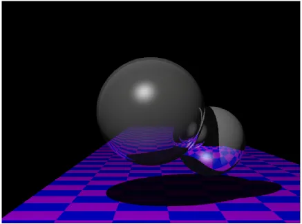
Fig-ure 5.1 shows an example of type of ray traced scene rendered to analyze
[image:63.612.91.528.307.632.2]partitioning performance.
![Figure 1.1: GFLOPS Performance Comparison of Modern GPUs vs. CPUs. Courtesy ofNVIDIA [10].](https://thumb-us.123doks.com/thumbv2/123dok_us/57389.5314/22.612.101.489.178.448/figure-gflops-performance-comparison-modern-gpus-courtesy-ofnvidia.webp)
![Table 3.1: Selection of graphics devices and their respective compute models [10].](https://thumb-us.123doks.com/thumbv2/123dok_us/57389.5314/39.612.130.487.196.272/table-selection-graphics-devices-respective-compute-models.webp)
![Figure 4.4: Performance Comparison (CPU v.s. CELL v.s. CUDA) [5].](https://thumb-us.123doks.com/thumbv2/123dok_us/57389.5314/57.612.168.455.90.327/figure-performance-comparison-cpu-v-s-cell-cuda.webp)