Int. J. Electrochem. Sci., 13 (2018) 11762 – 11776, doi: 10.20964/2018.12.28
International Journal of
ELECTROCHEMICAL
SCIENCE
www.electrochemsci.org
Nano-sized Tin Oxide-Modified Graphite Composite as Efficient
Anode Material for Lithium Ion Batteries
Chia-Chin Chang1,4,*, Li-Chia Chen1, Tai-Ying Hung2, Yuh-Fan Su1, Huang-Kai Su1, Jarrn-Horng Lin2, Chih-Wei Hu3, Lakshmanan Saravanan4, Tsan-Yao Chen3
1 Department of Greenergy, National University of Tainan, Tainan 70005, Taiwan 2 Department of Material Science, National University of Tainan, Tainan 70005, Taiwan
3 Department of Engineering and System Science, National Tsing Hua University, Hsinchu 30013,
Taiwan
4 R & D Center for Li-ion Battery, National University of Tainan, Tainan 70005, Taiwan *E-mail: [email protected]
Received: 17 July 2018 / Accepted: 9 September 2018 / Published: 5 November 2018
Nano-sized tin based compounds dispersed graphite composites, synthesized by the electroless plating process and pyrolysis method, act as efficient anode materials for lithium ion batteries (LIBs). The nano-sized tin complexes on the graphite surface can be obtained through a simple chemical reaction between Sn(BF4)2 and Na2S2O4 in aqueous solution and completely converted to SnO2 after
pyrolysis. The synthesized tin-modified graphite composites were characterized by X-ray diffraction (XRD), field-emission scanning electron microscopy (FE-SEM), and high-resolution transmission electron microscopy (HRTEM). The electrochemical performance of the composites for application as anode materials in lithium-ion batteries was investigated. The average particle size of nano-SnO2 is
~14.7 nm, as determined by HRTEM. Results of infrared spectra and electrochemical properties indicate that such an optimized nano Sn-based compound on graphite influences the formation of the thin solid electrolyte interface (SEI) in the electrode and thus improves the cycling performance, with high efficiency of 97.3% in LIBs. Nyquist plots show that during Li+ intercalation, the thin SEI film
and the low charge transfer resistance of SnO2-modified graphite composite anode plays important
roles in improving the electrochemical properties of LIBs.
Keywords: Graphite; SnO2; Anode; Electroless method; Lithium ion battery
1. INTRODUCTION
anode in commercial LIBs owing to their lower potential plateau, acceptable capacity, and low cost [4]. However, their insufficient electrochemical performance (e.g. energy density, capacity) hinders the application of carbon materials in public transportation markets.
Sn-based composite oxides and alloys have an impressive specific capacity that overcomes the long-standing issues of the carbon anode in a LIB [5]. However, Sn-based composite anode materials exhibit rapid capacity fading owing to the pulverization and structural destruction of electrode materials caused by large changes in volume and severe particle aggregation during cycling. Recently, it has been found that Sn-based composites in combination with ductile carbon materials could effectively alleviate the multi-cycle capacity fading [6]. In such a configuration, carbon materials provide sufficient local space for facile accommodation of volume expansion, thereby preventing aggregation of LixSn during lithiation/delithiation processes. Furthermore, SnO2 particles are not only
a high capacity Li-intercalation material but also enhance the lithiation/delithiation behaviors of SEI between the electrolyte and the graphite surface [7]. For Sn composites/carbon anodes, nano-sized and uniformly distributed tin compounds can achieve better electrochemical performance [8-10].
There are many ways to prepare Sn compounds on graphite anode materials, such as high-energy ball-milling [11], the hydrothermal process [12], the hydrolysis method [13], microemulsion techniques [14], the pyrolysis technique [15], electroplating [16], and electroless plating [17]. Electroless plating is an efficient method to deposit Sn-based compounds on graphite for LIB application. Various Sn-based compounds, including Sn nanoparticles [18] on nanoporous Au, Sn thin film [19] for Sn-Cu alloy, a Sn-Ni alloy layer [20], Sn-P-O compounds [17], a SnO2/Cu layer [21],
Sn-Zn film [22], and Ni-Sn-P compounds [23] prepared by electroless plating have been reported. In this study, we focused mainly on synthesizing a SnO2-modified graphite composite anode with an
optimized small quantity (~5%) of nano-sized SnO2 (14.7 nm) dispersed homogeneously on graphite
surface. This article describes mainly the formation of a highly stable SEI that preserves the high ionic conductivity to increase the diffusion of Li+, and the presence of Sn/SnO2 nanoparticles increases the
electron transport and protects the graphite surface from electrolyte decomposition.
In this study, we developed a composite anode of graphite deposited with nano-size tin based compounds (tin sulfide and/or tin oxide) by combining electroless plating and pyrolysis methods. The effects of electroless plating conditions on the composition, morphology, crystal structure and particle size of the Sn-based composites on graphite, and their electrochemical performance when applied as the anode in LIBs, were investigated.
2. EXPERIMENTAL
2.1 Preparation of Sn-graphite composite anode
Natural graphite powders (China Steel Chemical Co., Taiwan) with an average particle size of 19.89 nm and a Brunauer-Emmett-Teller (BET) surface area of 5.0 m2 g-1 was used in the process. The
dissolving 50 ml of Sn(BF4)2 (50% aqueous solution, Acros Organics) and 41.5 ml of HBF4 (35%
aqueous solution, Panreac) in 408.5 mL of de-ionized water under stirring at various controlled (bath) temperatures, and natural graphite (NG) powder was then added into the solution. Subsequently, an appropriate amount of Na2S2O4.5H2O (99.5%, Hsing Chia Chemical Industrial Co.) solution with 50
ml of HBF4 was immediately added into the metal solution and strongly stirred at the same
temperature for 30 min.
The Sn-based modified graphite powder was filtered from the solution and then rinsed with de-ionized water and alcohol to remove the residual sulfur until the pH value of the rinsing water reached 7. After the rinsing, the resultant powder was dried in a conventional vacuum oven, at room temperature for 3 h and then increases to 90 C in 30 min in vacuum before being dried for another 12 h. Finally, the powder was sieved with 200 µm mesh and defined as modified graphite. The Sn-modified graphite powder was further annealed in a furnace at 450 C under N2 atmosphere for 2 h,
and the obtained powder was defined as annealed Sn-graphite.
2.2 Material analysis
A scanning electron microscope (SEM, JEOL JSM35 operating at 20 kV) and energy dispersive spectroscopy (EDS) were used to evaluate the surface morphology and perform surface semi-quantitative analysis of the various graphite anodes, respectively. The crystal structure was determined primarily by means of powder X-ray diffraction (XRD) using a RIGAKU D/MAX2500 diffractometer, Cu K radiation, and a scan range of 20–80 degrees.
After three charge-discharge processes, the anodes were rinsed with DEC to remove the electrolyte and dried out under vacuum at 90 C for 2 h before further material analysis. The morphology and particle size of the Sn-based nanoparticles dispersed on graphite were observed by using a transmission electron microscope (Philips/FEI Tecnai 20 G2 S-Twin transmission electron microscope including a CCD camera with the Diffpack program for diffraction pattern analysis and FEI E.O Tecnai F20 G2 MAT S-TWIN field emission gun transmission electron microscope) with digital micrograph software. Particles selected from random regions were analyzed for structural characterization by high resolution transmission electron microscopy (HRTEM). The particle size distribution was measured by image analyzer (Optimas and Quiantikov). Infrared absorption spectra were recorded ex-situ, with a Perkin-Elmer Spectrum 100 FTIR system. All spectra were recorded at room temperature using an attenuated total reflectance (ATR) mode with a resolution of 2 cm-1 and a total of 128 scans.
2.3 Electrochemical measurements
An electrolyte of 1 mol dm-3 LiPF
6 in a 50:50 w/w mixture of ethylene carbonate (EC) and
1. Half-cells were fabricated with standard CR2032 coin cell hardware. In a constant current mode, the
charge/discharge cycle behavior was evaluated galvanostatically at 0.325 mA cm-2 over the range of
0.003–2.0 V. All the above experiments were performed in a glove box filled with argon. The electrochemical impedance spectroscopy (EIS) test of all the graphite electrodes was measured after 3 cycles to further investigate the mechanism of the enhanced electrochemical performance of the SnO2
-graphite composites. EIS measurement was performed on the coin cell by coupling the potentiostat with an Autolab frequency response analyzer locked in an amplifier and an impedance phase analyzer. A sinusoidal amplitude modulation of ± 10 mV was used over a frequency range of 0.01 Hz to 1 MHz.
3. RESULTS AND DISCUSSION
3.1 The effects of Na2S2O4 concentration on Sn-modified graphite anodes
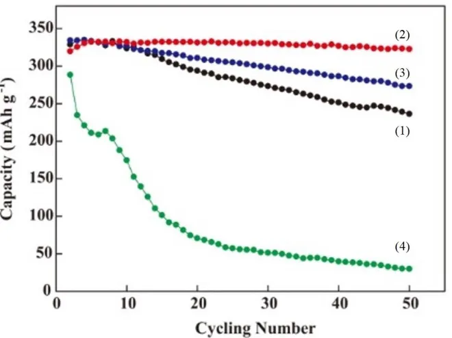
Figure 1. Cycling performance of pristine graphite (1, black) and the graphite anodes modified by 0.25 (2, red), 0.5 (3, blue), and 1 (4, green) mol dm-3 Na2S2O4. The modified reactions were all in
Sn(BF4)2 solution with the same concentration at 60 C.
The cycling performances of the various concentrations of Na2S2O4 reductant on Sn-modified
graphite anodes are shown in Figure 1. As indicated, the capacity of the pristine graphite remained steady in the first 10 cycles and then progressively decreased by 0.6% per cycle (vs. C0) until the 50th cycle. Such a fading rate could be attributed to passivation-induced irreversibility caused by the formation of Li+-O-C complexes at defect sites on the graphite surface. In treated with a solution of 0.25 mol dm-3 Na2S2O4, the irreversibility of the Sn-modified graphite was completely eliminated at
[image:4.596.130.460.318.565.2]
mol dm-3 resulted in dramatic fading of the capacity of the Sn-modified graphite anode. The significantly different behaviors of the anode modified by 1 mol dm-3 Na
2S2O4 could be ascribed to a
high sulfur content. Such an impurity induces a large irreversible reaction in subsequent charge-discharge processes, leading to the formation of a thick solid electrolyte interface (SEI) on the graphite surface [24]. Based on the above results, 0.25 mol dm-3 Na2S2O4 was chosen for reaction with a metal
precursor, Sn(BF4)2, to form the Sn-based composites on a graphite surface. To obtain the composite
with optimum performance, the effects of the plating temperature on the capacity of Sn-modified graphite anodes were also examined.
3.2 The effects of plating bath temperature on Sn-modified graphite anodes
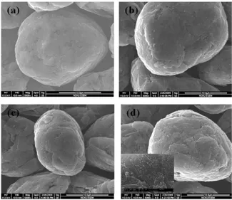
Figure 2. SEM images of (a) pristine graphite and the Sn-modified graphite reacting with 0.25 mol dm-3 Na2S2O4 at (b) 40, (c) 60 and (d) 80 C. Inset in (d) shows the annealed Sn-graphite
sample (SnO2 nanoparticles on graphite).
Table 1. EDS results of the Sn-modified graphite powder expressed as weight percentage.
Element (wt.%) Plating bath
Temp.
C O S Sn
40 C 91.98 1.67 1.68 4.67
60C 94.47 2.09 0.80 2.64
[image:5.596.135.460.260.541.2] [image:5.596.87.508.645.738.2]
SEM images of Sn-modified graphite anodes prepared at different bath temperatures are shown in Figure 2. Accordingly, nanoparticles of the Sn-based compound were distributed on the graphite surface, and their density and size increased with increases in the preparation temperature. Constituents with the corresponding compositions of experimental samples were determined by EDS analysis. As shown in Table 1, the weight ratio of O atoms increased along with the reaction temperature, whereas that of S atoms followed the opposite trend. Such a phenomenon can be explained by the reaction kinetics of the reduction agent (Na2S2O4) with Sn, at defect sites on the graphite surface. Given that
identical reaction times were used for the reduction of complexes (S2O42-) to Sn cations in all samples,
uncompleted Sn decoration defects on the graphite surface could be expected. In this condition, an amorphous Sn(S2O4)2 complex layer formed on the graphite surface. Increasing the plating bath
temperature higher than 80 C, substantially increased the O content to 5 wt%, implying the formation of tin oxide (SnO2) on the graphite surface. At such a high temperature (~80 C), the rates of the
formation of Sn-S complexes and their subsequent condensation and dissociation into Sn dramatically increased. Therefore, the formation of multi-phase SnO2 was facilitated on the heterogeneous graphite
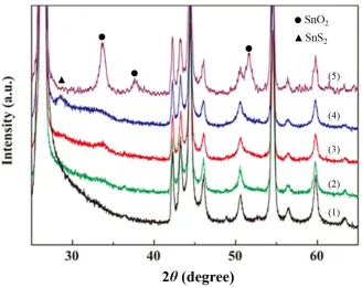
surface. This finding was further confirmed by XRD analysis. As shown in Figure 3, SnS and SnS2
phase appeared in the Sn-modified graphite anode after plating at 60 C [24-26], while SnO2 appeared
after pyrolysis, as will be discussed below. In agreement with the results of EDS analysis, amounts of pure Sn and S gradually decreased with increasing temperature in the electroless plating solution. Those results indicated the simultaneous formation of tin oxides and sulfides on the graphite surface in an electroless plating treatment. Furthermore, the deposited tin compounds could be well-controlled to be either nano-sized or amorphous.
Figure 3. XRD of pristine graphite (1, black), the Sn-modified graphite reacting with 0.25 mol dm-3
Na2S2O4 at 40 (2, green), 60 (3, red) and 80 ºC (4, blue), and the annealed Sn-graphite (5,
[image:6.596.128.456.440.701.2]
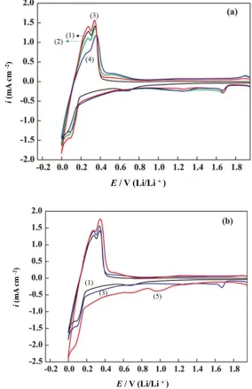
Cyclic voltammetry measurement was employed to determine the redox reversibility and kinetics of pristine and Sn-modified graphite with lithium ions. Cyclic voltammograms (CVs) of the first scan of graphite electrodes are shown in Figure 4(a). For the anode with pristine graphite (curve (1)), the broad peak starting at 0.90 V and centered around 0.70 V, presumably revealed the formation of a passivation film [13, 36, 27]. The potential for lithium insertion is ~0.0–0.2 V, whereas the potential for lithium extraction is ~0.5 V [28].
Figure 4. (a) CVs of the first cycle for pristine graphite (black, 1) and the Sn-modified graphite reacting with 0.25 mol dm-3 Na
2S2O4 at 40 (green, 2), 60 (red, 3) and 80 C (blue, 4). (b) CVs
of the first cycle for pristine graphite (black, 1), the Sn-modified graphite (60 C, blue, 3), and the annealed Sn-graphite (red, 5)
[image:7.596.154.438.192.631.2]
SnS2 [26, 29-32], and the formation of the solid electrolyte interface (SEI) [26]. In the lithiation
process in the first scanning cycle, a small hump in the potential range of 0.2–0.6 V appeared in the CVs of pristine graphite and was attributed to the formation of SnxLiy alloys [27]. As compared to the
CVs of pristine graphite, the further enhanced peak intensity at 0.2–0.4V indicated a reduced formation energy (facilitated crystal growth) of the SnxLiy alloy in the Sn-modified graphite, and an anodic peak
at 0.60 V was assigned to lithium de-alloying [33]. The magnitudes of lithiation and de-lithiation peaks for the SnxLiy alloys were significantly decreased, indicating a reduction of the reversible capacity with
increasing CV cycles.
As shown in Figure 4(a), the reversibility of lithium insertion/de-insertion between 0 and 0.4 V was obviously enhanced by depositing the proper amount of tin on the graphite surface by electroless plating at 60 C (curve (3)). The structural evolutions between SnS and SnO (or SnO2) with respect to
plating temperature of the Sn complex were complementarily elucidated by cross-referencing the results of XRD (Fig. 3) and EDS (Table 1). These results showed that the Li intercalation/de-intercalation behavior at graphite electrodes corresponded to the amount of tin compounds decorating the surface. The amount of Sn complex / Sn oxide was defined by the density of sulfuric complexes on the graphite surface and was possibly controlled by the plating temperature (i.e., the reaction kinetics of Sn-S2O4 complexes followed by oxidation) [32]. For the composite prepared in the electroless
plating condition at 40 C, the presence of large amounts of tin, sulfur, and multiple phases of tin oxide on the graphite surface were responsible for its irreversible capacity loss, which was the largest among all the samples. Also, the size of the tin oxide nanoparticles on the graphite surface was larger than that of low-temperature samples (Fig. 2(d)). The lithium insertion/de-insertion currents between 0 and 0.4 V may have been hindered by the larger particle size and the presence of impurities on the graphite surface. These cathodic peaks at around 0.6, 1.25, and 1.75 V almost disappeared after scanning for 4 cycles due to the irreversible reduction of SnS and SnS2, and the oxidation of Li2S at 1.9 V [26, 32].
The electrochemical behavior of the annealed Sn-graphite anode is illustrated in Figure 4 (b), along with the curves of Sn-modified and pristine graphite anodes for comparison. It should be noted that the signals indicating the reaction between Li-ion and SnS2 at 1.75 and 1.25 V disappeared, while
on the other hand, the cathodic peak related to the formation of Sn metal and Li2O was present at
around 1.0 V [34-37]. The impurities such as tin, sulfur, and tin sulfide on the graphite surface were transferred to tin oxide (SnO2) by thermal treatments, which was confirmed by the significant SnO2
peaks in the XRD (Fig. 3, curve 5). Based on the literature [38], it was also considered that the SnO2
nanoparticles would protect the surface of the carbon substrate (graphite) from SEI formation. The reversible properties and the lithium insertion/de-insertion currents between 0 and 0.4 V were obviously enhanced by annealing at 450 C. From Fig. 4 (a) and 4 (b), it is clear that the reversibility of Li-graphite intercalation/de-intercalation was enhanced in the Sn-modified graphite anode prepared at 60 C electroless plating and at 450 C annealed Sn-graphite anodes, with SnO2 nanoparticles (NPs)
process.
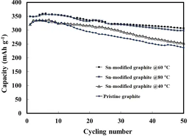
The cycling performances of the Sn-modified graphite anodes prepared at different temperatures are compared with that of pristine graphite in Figure 5. It can be clearly seen that the Sn-modified graphite anodes prepared at 60 and 80 C had better cycling performance than those of anode prepared at 40 C and pristine graphite, exhibiting an initial capacity value of 360 mAh g-1. The formation of tin oxides and tin sulfides on the graphite surface was expected to derive inactive tin species as buffers to prevent particle aggregation of the tin during the cycling process. It has previously been reported [14] that the active sites on the graphite surface help to bind and stabilize the SnO2
particles and thereby reduce the mobility of the particles on the graphite surface, suppressing particle agglomeration. They also buffer the volume changes during cycling (Li-ion intercalation and de-intercalation reactions) and enhances Li-ion storage, resulting in higher capacity retention and good cyclic performance.
Figure 5. Cycling performances of pristine (), and Sn-modified graphite anodes reacting with 0.25 mol dm-3 Na2S2O4 at 40 (), 60 () and 80 C (*).
To eliminate the effect of residual sulfur (S) on the cycling performance, the Sn-modified graphite anode obtained at 60 C was annealed at 450 C for 2 h (Note that the evaporation point of S is 444.7 C). The formation of SnO2 after this pyrolysis was clearly observed by XRD, as shown in
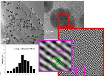
Figure 3 [35], while no significant differences in surface morphology between the Sn-modified graphite and annealed Sn-graphite anodes were found. TEM images of the annealed Sn-graphite anode are shown in Figure 6. It can be clearly observed that the SnO2 nanoparticles preferred to deposit on
[image:9.596.102.487.301.584.2]
effect of the functional groups on the edge of graphite, such as –OH or –COOH [39]. The high resolution TEM image in Figure 6 revealed that the SnO2 particles were crystalline in structure. The
inter-planar spacing was 0.34 nm, which corresponds to the (110) plane of a rutile SnO2 lattice. The
average size of these SnO2 nanoparticles on the graphite surface, determined by TEM particle size
distribution analysis (Figure 6), was 14.7 ± 2.1 nm. The nanoscale dimension shortens the diffusion length of SnO2 and graphite for both Li+ and e–, significantly improving the rate and efficiency of
lithiation/delithiation and electron transport, as governed by Fick’s first law (Eqn. 1), where is characteristic diffusion time constant, L is diffusion length and D is material-dependent diffusion coefficient [40].
= 𝐿2
𝐷 (1)
Infrared spectra of pristine, Sn-modified graphite, and annealed Sn-graphite anodes after the cycling test are presented in Figure 7. Verma et al. specified that EC is a highly reactive solvent that forms a mixture of Li2CO3 and ROCO2Li to dominate the lithiated graphite surface chemistry (SEI
[image:10.596.98.499.330.622.2]structure) [41].
Figure 6. TEM and high resolution TEM images of the annealed Sn-graphite anode and histogram of the size distribution of SnO2 on the graphite surface.
In this study, the (CH) peaks at 2826 and 2988 cm–1 indicated the formation of alkoxy species, including CH3OLi and ROCO2Li in pristine graphite, via reaction of (CH2OCO2Li)2 with HF [42, 43].
After modification of the graphite with Sn-based complex, the IR peaks at 2826 and 2988 cm–1 shifted to 2855 and 2935 cm–1. This chemical shift could be attributed to the vibration responses of (CH2) in
compounds on the graphite surface. Those species inhibited the reaction of (CH2OCO2Li)2 with HF
and protected the carbon surface from electrolyte decomposition. Careful examination of the IR peaks of the annealed Sn-graphite anode showed behavior more symmetrical than that of the Sn-modified anode. This difference implied that the satiability of SEI film was higher in the anode with annealed Sn-graphite than the anodes with other experimental samples. EIS is a well-established technique for studying the electrode kinetics of electrode materials. Figure 8 presents the Nyquist plots of the pristine, Sn-modified graphite, and annealed Sn-graphite anode cells after 3 cycles at room temperature. The plots consist of a semicircle in the high and medium frequency ranges and a 45 inclined line in the low frequency range.
Figure 7. Infrared spectra of (1) pristine, (2) the modified graphite, and (3) the annealed Sn-graphite anodes after the cycling tests.
[image:11.596.152.441.250.475.2] [image:11.596.139.450.546.731.2][image:12.596.60.545.183.537.2]
The semicircle was assigned to the charge transfer resistance, which is related to the charge transfer through the electrode/electrolyte interface (SEI). The inclined line corresponded to the diffusion properties (migration) of lithium ions within the electrode.
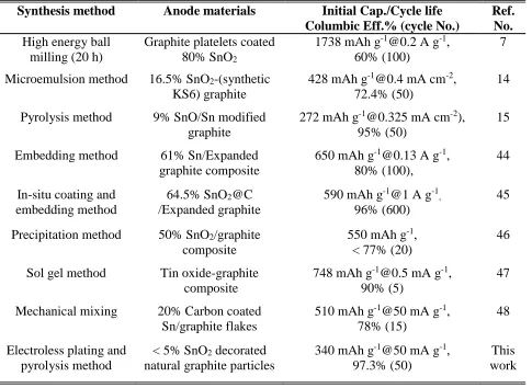
Table 2. Performance comparison of similar Sn/SnO2-gaphite anode materials reported previously.
Synthesis method Anode materials Initial Cap./Cycle life Columbic Eff.% (cycle No.)
Ref. No. High energy ball
milling (20 h)
Graphite platelets coated 80% SnO2
1738 mAh g-1@0.2 A g-1,
60% (100)
7 Microemulsion method 16.5% SnO2-(synthetic
KS6) graphite
428 mAh [email protected] mA cm-2, 72.4% (50)
14 Pyrolysis method 9% SnO/Sn modified
graphite
272 mAh g-1@0.325 mA cm-2),
95% (50)
15 Embedding method 61% Sn/Expanded
graphite composite
650 mAh [email protected] A g-1, 80% (100),
44 In-situ coating and
embedding method
64.5% SnO2@C
/Expanded graphite
590 mAh g-1@1 A g-1 ,
96% (600)
45
Precipitation method 50% SnO2/graphite
composite
550 mAh g-1, < 77% (20)
46 Sol gel method Tin oxide-graphite
composite
748 mAh [email protected] mA g-1, 90% (5)
47 Mechanical mixing 20% Carbon coated
Sn/graphite flakes
510 mAh g-1@50 mA g-1, 78% (15)
48
Electroless plating and pyrolysis method
< 5% SnO2 decorated
natural graphite particles
340 mAh g-1@50 mA g-1, 97.3% (50)
This work
The diameter of the semicircle for the annealed Sn-graphite anode was much smaller than those of the pristine and Sn-modified graphite anodes, suggesting that the charge-transfer resistance of the annealed Sn-graphite (SnO2 NPs deposited graphite anode) was lower than that of the others. These
results confirmed that the thin SEI film could preserve the high ionic conductivity of the annealed Sn-graphite composite electrode and thus that the combination of SnO2 nanoparticles and graphite greatly
enhances the rapid lithium insertion/extraction, resulting in significant improvement of the electrochemical performance over those of pristine and Sn-modified graphite electrodes. The electrochemical performances of Sn/SnO2-graphite composite anodes from the literature, prepared
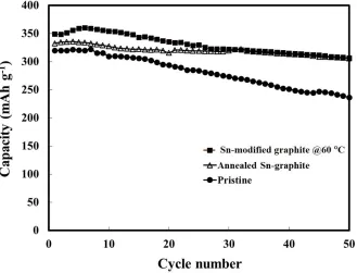
Figure 9. Cycling performance of the pristine (), the modified graphite (), and the annealed Sn-graphite () anodes.
We anticipated that the improvement from the enhanced conductive and buffering matrix of graphite would keep the entire composite stable. As shown in Figure 9, although the pyrolysis process decreased the initial discharge capacity, the anode with annealed Sn-graphite demonstrated higher stability (capacity efficiency = 97.3%) than that of the anode with Sn-modified graphite (capacity efficiency = 83.3%) in a long-term performance test after 50 cycles. As a result, the cyclic performance of the composite materials was enhanced notably, with a reversible capacity as high as 330 mAh g-1
after 50 cycles. 4. CONCLUSION
Graphite decorated with nano-tin oxides of about 14.7 nm in size, has been synthesized by combining the electroless plating process and pyrolysis method. This composite material acts as an efficient composite anode in LIBs. Due to the pyrolysis treatment, the tin sulfide (SnS and/or SnS2)
present in the composite can be completely converted to SnO2, which obviously retards the capacity
fading of the LIB anode in cycling tests. As revealed by infrared spectroscopic analysis, the structural ordering of the SEI layer is improved in the presence of Sn-based compounds on the graphite surface. These features may also protect the graphite surface from electrolyte decomposition, thereby improving the ionic conductivity and electronic mobility, and therefore substantially enhance the cyclability of the graphite anode in LIBs. This investigation of SnO2-graphite composite as an efficient
anode material for LIBs has shown that the SnO2-graphite composite can deliver high stability and a
ACKNOWLEDGEMENTS
The authors are grateful for the financial support of the Hopax Chemicals Mfg. Co., Taiwan, and the Ministry of Science and Technology of Taiwan under the following contracts: MOST 106-3113-E-006-003-CC2, and MOST 106-2912-I-024-502. The authors also thank the personnel of the National Synchrotron Radiation Research Center (NSRRC), Hsinchu, Taiwan, for their help with various synchrotron-based measurements.
References
1. D. Larcher and J.M. Tarascon, Nat. Chem., 7 (2015) 19. 2. J.W. Choi and D. Aurbach, Nat. Rev. Mater., 1 (2016) 16.
3. W. Liu, M.S. Song, B. Kong and Y. Cui, Adv. Mater., 29 (2017) 34.
4. S. Goriparti, E. Miele, F. De Angelis, E. Di Fabrizio, R.P. Zaccaria and C. Capiglia, J. Power Sources, 257 (2014) 421.
5. M. Zhang, T. Wang and G. Cao, Int. Mater. Rev., 60 (2015) 330.
6. Y.F. Deng, C.C. Fang and G.H. Chen, J. Power Sources, 304 (2016) 81.
7. M.H.N. Vincent, S. Wu, P. Liu, B. Zhu, L. Yu, C. Wang, H. Huang, Z.J. Xu, Z. Yao, J. Zhou, W. Que and L.B. Konga, Electrochim. Acta, 248 (2017) 440.
8. J.S. Chen and X.W. Lou, Small, 9 (2013) 1877.
9. Y. Zhao, X.F. Li, B. Yan, D.J. Li, S. Lawes and X.L. Sun, J. Power Sources, 274 (2015) 869. 10.L.H. Liu, F. Xie, J. Lyu, T.K. Zhao, T.H. Li and B.G. Choi, J. Power Sources, 321 (2016) 11. 11.F. Ye, B. Zhao, R. Ran and Z. Shao, Chem. Eur. J., 20 (2014) 4055.
12.S. Chen, Y. Wang, H. Ahn and G. Wang, J. Power Sources, 216 (2012) 22. 13.J.Y. Lee, R.F. Zhang and Z.L. Liu, Electrochem. Solid State Lett., 3 (2000) 167. 14.Y. Wang, J.Y. Lee and B.H. Chen, J. Electrochem. Soc., 151 (2004) A563.
15.C.C. Chang, S.J. Liu, J.J. Wu and C.H. Yang, J. Phys. Chem. C, 111 (2007) 16423. 16.A. Ulus, Y. Rosenberg, L. Burstein and E. Peled, J. Electrochem. Soc., 149 (2002) A635. 17.T. Fang, L.Y. Hsiao, J.G. Duh and S.R. Sheen, J. Power Sources, 160 (2006) 536.
18.Y. Yu, L. Gu, X.Y. Lang, C.B. Zhu, T. Fujita, M.W. Chen and J. Maier, Adv. Mater., 23 (2011) 2443.
19.L.G. Xue, Z.H. Fu, Y. Yao, T. Huang and A.S. Yu, Electrochim. Acta, 55 (2010) 7310. 20.Y. Kong, J.Q. Shao, W.C. Wang, Q.F. Liu and Z.D. Chen, J. Alloy Compd., 477 (2009) 328. 21.C.L. Hsieh, D.S. Tsai, W.W. Chiang and Y.H. Liu, Electrochim. Acta, 209 (2016) 332. 22.Q.A. Ru, W. Peng, Z.W. Zhang, S.J. Hu and Y.L. Li, Rare Metals, 30 (2011) 160. 23.L.Y. Hsiao, T. Fang and J.G. Duh, Electrochem. Solid State Lett., 9 (2006) A232. 24.H. Mukaibo, A. Yoshizawa, T. Momma and T. Osaka, J. Power Sources, 119 (2003) 60. 25.J.T. Zai, K.X. Wang, Y.Z. Su, X.F. Qian and J.S. Chen, J. Power Sources, 196 (2011) 3650. 26.Q.Q. Zhang, R. Li, M.M. Zhang, B.L. Zhang and X.L. Gou, Electrochim. Acta, 115 (2014) 425. 27.G.X. Wang, J. Yao, H.K. Liu, S.X. Dou and J.H. Ahn, Electrochim. Acta, 50 (2004) 517.
28.C.C. Chang, L.J. Her, L.C. Chen, Y.Y. Lee, S.J. Liu and H.J. Tien, J. Power Sources, 163 (2007) 1059.
29.T. Brousse, S.M. Lee, L. Pasquereau, D. Defives and D.M. Schleich, Solid State Ion., 113 (1998) 51.
30.T. Momma, N. Shiraishi, A. Yoshizawa, T. Osaka, A. Gedanken, J.J. Zhu and L. Sominski, J. Power Sources, 97-8 (2001) 198.
31.M. Sathish, S. Mitani, T. Tomai and I. Honma, J. Phys. Chem. C, 116 (2012) 12475.
34.M.V. Reddy, L.Y.T. Andreea, A.Y. Ling, J.N.C. Hwee, C.A. Lin, S. Admas, K.P. Loh, M.K. Mathe, K.I. Ozoemena and B.V.R. Chowdari, Electrochim. Acta, 106 (2013) 143.
35.K. Chang, W.X. Chen, H. Li and H. Li, Electrochim. Acta, 56 (2011) 2856.
36.J.G. Ren, J.B. Yang, A. Abouimrane, D.P. Wang and K. Amine, J. Power Sources, 196 (2011) 8701. 37.C.C. Hou, S. Brahma, S.C. Weng, C.C. Chang and J.L. Huang, Appl. Surf. Sci., 413 (2017) 160. 38.K.E. Aifantis, S. Brutti, S.A. Hackney, T. Sarakonsri and B. Scrosati, Electrochim. Acta, 55 (2010)
5071.
39.G.C. Herdt, D.R. Jung and A.W. Czanderna, Prog. Surf. Sci., 50 (1995) 103. 40.Y. Wang, H. Li, P. He, E. Hosono and H. Zhou, Nanoscale, 2 (2010) 1294. 41.P. Verma, P. Maire and P. Novak, Electrochim Acta, 55 (2010) 6332.
42.D. Aurbach, Y. Gofer, M. Benzion and P. Aped, J. Electroanal. Chem., 339 (1992) 451.
43.D. Aurbach, B. Markovsky, I. Weissman, E. Levi and Y. Ein-Eli, Electrochim. Acta, 45 (1999) 67. 44.Y. Yan, L. Ben, Y. Zhan and X. Huang, Electrochim. Acta, 187 (2016) 186.
45.L. Ming, B. Zhang, J.F. Zhang, X.W. Wang, H. Li, C.H. Wang, J. Alloy Compd., 752 (2018) 93. 46.W.J. Jin, S.M. Park, I.P. Hong, S.Y. Lee and M.S. Kim, Solid State Phenom., 124/126 (2007) 1051. 47.S. M. Hasanaly, AIP Conf. Proc., 1217 (2010) 187.
48.T. Morishita, T. Hirabayashi, T. Okuni, N. Ota and M. Inagaki, J. Power Sources, 160 (2006) 638.