Int. J. Electrochem. Sci., 12 (2017) 1094 – 1105, doi: 10.20964/2017.02.05
International Journal of
ELECTROCHEMICAL
SCIENCE
www.electrochemsci.org
Short Communication
Corrosion Inhibition of Aluminum in Hydrochloric acid
Solution Using Ceria Doped Polyvinyl Chloride Nanofiber.
Soha Gaballah1, 2,*, Nader Shehata1,3,4, Mohamed Shaaban2, Shaaban Nosier2, Ahmed Hefnawy5, Aya Hamed1, 4, Effat Samir1, 6
1
Center of Smart Nanotechnology and Photonics (CSNP), SmartCI Research Center, Alexandria University, Alexandria 21544 Egypt.
2
Department of Chemical Engineering, Faculty of Engineering, Alexandria University, Alexandria 21544 Egypt.
3
USTAR Bioinnovations center, Utah State University, Logan 84341 Utah
4
Department of Engineering Mathematics and Physics, Faculty of Engineering, Alexandria University, Alexandria 21544 Egypt.
5
Department of Materials Science t, Institute of Graduate Studies and Research, Alexandria University, Alexandria, 21544 Egypt
6
Department of Electrical Engineering, Faculty of Engineering, Alexandria University, Alexandria 21544, Egypt
*
E-mail: soha_gaballah@mena.vt.edu
Received: 4 September 2016 / Accepted: 23 November 2016 / Published: 30 December 2016
Keywords: aluminum corrosion, polyvinyl chloride (PVC), nanofiber coating, ceria nanoparticles, corrosion resistance.
1. INTRODUCTION
Aluminum is considered as the second most common metal in the Earth’s crust. Aluminum, and its alloys are widely used in many applications as its low cost, high strength accomplished with low density and high thermal, and electrical conductivity .These advantages make it useful in different industries such as marine applications, aerospace, food packing, electronics, heat exchangers in petroleum industry, scrubbers and storage tanks [1-4]. Generally, Aluminum forms a protective invisible passive oxide film on its surface upon exposure to an aqueous solution ,but this oxide film does not offer sufficient protection against strong acidic, and alkaline solutions because of its solubility at these conditions, which increases the rate of corrosion .To decrease electrochemical corrosion of aluminum, some coaters such as synthetic polymers, organic, and inorganic compounds were used to isolate aluminum surface from corrosion medium by forming more resistant oxide film on metal surface [5-11]. Researchers found that rare earth elements such as cerium, lanthanum, neodymium, and yttrium might be an effective corrosion protection for aluminum because they control cathodic reaction. The maximum corrosion protection efficiency is improved with cerium because of the presence of Ce3+ [12-14]. In this research , the synthesized corrosion coat contains one of the promising lanthanide nanomaterials; cerium oxide (ceria) nanoparticles, which offer an advantage of tiny dimensions for being applicable of injecting them inside nanofiber; “in-situ” with polyvinyl chloride (PVC), nanofibers formed by the electrospinning technique. Electrospinning technique has been chosen as the fabrication technique for the formed nanocomposite. With a simple operation, ceria NPs could be embedded easily in the formed PVC nanofibers with the ability to scale- up to fabricate large volumes of the resulted nanocomposite [15]. It has been widely used in many applications, such as biomedical, gas sensors, electronics, and corrosion inhibition [16-21]. In this work, we report the synthesis of ceria NPs, and then embedded in-situ in polyvinyl chloride (PVC) nanofiber coating on aluminum substrates as a collector in the electrospinning process. The effect of polymeric coat on the corrosion behavior of aluminum in 0.1M HCl was examined using potentiodynamic polarization, and impedance spectroscopy. The surface of aluminum, and the Polymeric coated aluminum surface before, and after immersing in HCl were characterized by using scanning electron microscope (SEM). The synthesized nanocomposite has been optically characterized using absorbance spectroscopy, direct bandgap calculations, and fluorescence spectroscopy. These optical characterizations can give proof of the existence of oxygen vacancies inside the crystalline structure of ceria nanoparticles; which can adsorb the free radicals, and consequently reduce the rate of corrosion [22].
2. EXPERIMENTAL
2.1. Polymer and Nanoparticle Synthesis
described by chen and chang, but with slight modifications in precursors and synthesis procedure [23, 24]. This technique has been chosen as it is simple, has easy procedure, and needs reasonable cost precursors. For the preparation of ceria NPs; firstly, 0.5 gm of cerium (III) chloride heptahydrate (99.9%, Sigma-Aldrich, St. Louis, MO, United States) is mixed with 40 ml of distilled water in an open container. After that, 1.6 ml of ammonia is added as a solvent, and the whole solution is magnetically stirred for 1.5 hrs, in water bath at temperature around 60 °C. Finally, the solution is allowed to cool at room temperature over the stirrer for 22.5 hrs. The long stirring period helps in fracturing of any nanorods produced into nanoparticles. The produced mixture; is then centrifuged, and washed twice with distilled water, and ethanol to get rid of any unreacted cerium, and ammonia. Ceria NPs with various weight percentages are added in-situ to the PVC solution. The electrospun mixture is stirred for 30 minutes before electro spinning process.
2.2. Electrospinning
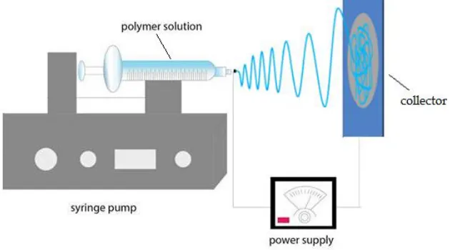
As shown in Figure 1; the electrospinning Setup consists of four main parts; high voltage power supply (model CZE1000R, Spellman High Voltage Electronics Corporation, Hauppauge, New York, United States), a syringe pump (NE1000-Single Syringe Pump, New Era, and Farmingdale, New York, United States), and a collector. The syringe pump regulates the feed rate of polymer solution, and a 5 mL plastic syringe with an 18 gauge metallic needle is used to hold the polymer solution. The voltage power supply is connected to the needle, and the collector is grounded. The distance between the needle tip and the collector is fixed at 15cm. The voltage difference between the needle, and target is 20 kV. The flow rate of the polymer solution is fixed at 9 mL/h. The fibers were collected on target metals, and the running time of electrospinning process per sample is about 30 min.
Figure 1. Schematic for electrospinning process
2.3. Corrosion test
[image:3.596.137.452.480.655.2]
reference electrode, respectively. Measurements were carried out with a GAMRY G 750 instrument, and accompanying electrochemical software version 5.3. The polarization curves were obtained potentiodynamically between -0.25V, and 0.25 V relative to the open circuit potential with a scan rate of 1 mV s-1. Electrochemical impedance spectroscopy experiments were conducted in a frequency range of 0.1 Hz - 100 kHz at open circuit potential by applying an alternating potential signal of 10 mV peak-to-peak. Echem analyst 5.5 software is used for graphing, and data fitting. All electrochemical experiments were carried out in aerated solutions under unstirred conditions at (30 ± 2) C.
2.4. Nanocomposite characterization
PVC nanofibers with embedded ceria NPs; are optically characterized by measuring its optical absorbance, and fluorescence intensity curves. UV-Vis spectrophotometer T92 has been used to measure optical absorbance in a wavelength within range from 300 to 700nm. Corresponding NFs band gap can be determined from absorbance curves as explained in results and discussion section.
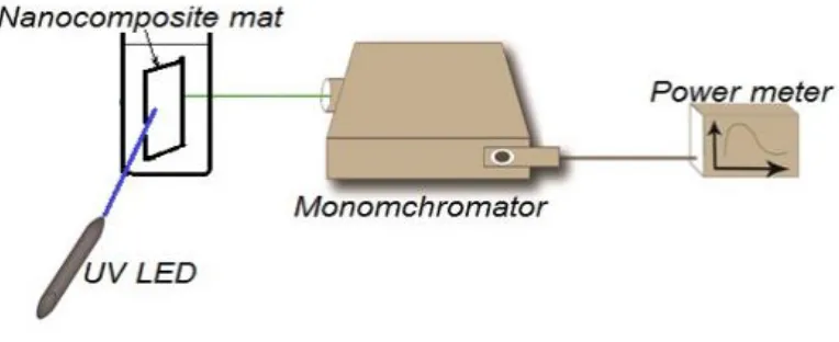
A setup of fluorescence spectroscopy is initiated by the authors for measuring the fluorescence intensity, as shown in Figure 2. Fluorescence setup consists of ultra-violet (UV) LED with 430nm excitation wavelength, Newport cornerstone 130 monochromator; which sweeps wavelength from 500 to 700nm and, measure corresponding frequency. Oriel photomultiplier tube (Newport PMT77340) is used as fluorescence intensity detector, and Newport 1918-R power meter is used to display PMT detection readings. For Fluorescence intensity measurement polymer NFs solid sample holder is positioned 45o between UV- LED and the input port of the monochromator. The output port of the monochromator was directly connected to PMT and consequently connected to the power meter.
Figure 2. Fluorescence intensity hand-made spectroscopy setup
[image:4.596.97.479.489.645.2]
software. The determination of mean size diameter of synthesized ceria NPs was observed by transmission electron microscopy (TEM) Panalytical's X'Pert PRO x-ray diffraction via Cu Kα
radiation ( λ=0.154 nm ) is used to measure XRD analysis of the synthesized nanoparticles.
3. RESULTS AND DISCUSSION
3.1. Polarization Measurements
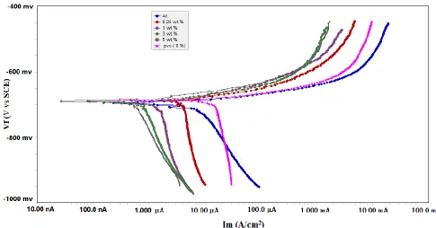
The polarization curves for the aluminum electrode coated with PVC NFs, and PVC NFs embedded in-situ ceria NPs with concentration ( 0.25,1,3,5 wt.%) in 0.1 M HCl at 25 ± 2°C, are shown in Figure3.Table 1 describes The values of corrosion current density (icorr), corrosion potential
(Ecorr), anodic Tafel slope (βa), cathodic Tafel slope (βc), Corrosion Rate (C.R), and inhibition
efficiency (IE%) obtained are illustrated in Table 1. Tafel fit routine provided by the Gamry Echem analyst software was used to calculate these values.It uses a non-linear chi-squared minimization to fit the data of the Stern-Geary equation. The inhibition efficiency was calculated from the following equation [25]:
(1)
where I and I are the corrosion current before and after addition of corrosion coat, respectively.
[image:5.596.50.535.442.696.2]
Table 1. Polarization parameters for aluminium in 0.1 M HCl with different coating materials at 25 ± 2°C.
Material βa (V.dec -1
)
βc
(V.dec-1) (µA.cm-1 )
-Ecorr
(mv) (mpy) C.R IE %
Al_substrate 30.20e-3 163.4e-3 4.96 695.0 6.389 0.00
PVC 40.20e-3 1.000e15 2.68 658.0 3.454 46
PVC-ceria 0.25 wt%
38.50e-3 1.000e15 2.38 683.0 2.045 52
PVC-ceria 1 wt%
38.90e-3 1.000e15 2.22 690.0 1.905 55.4
PVC-ceria 3 wt%
35.70e-3 1.000e15 1.37 694.0 1.760 72.4
PVC-ceria 5 wt%
32.30 e-3 733.1e-3 0.709 690.0 608.7e-3 85.7
The inhibitor is considered either an anodic-type, or cathodic-type inhibitor when the displacement in Ecorr is larger than 85 mV with respect to initial Ecorr [26,27].In the present study;the
maximum displacement was 37 mV, which indicates that the inhibitor is mixed-type. Adding PVC NFs, and PVC NFs embedded in-situ ceria NPs decreases the anodic dissolution of aluminum and retards the cathodic hydrogen evolution. Table 1 shows that the icorr values is reduced in the presence
of ceria NPs doped within PVC NFs and increasing of IE% . This result illustrates that the corrosion rate is decreased when coating the surface with PVC NFs embedded in-situ ceria NPs, and that the inhibition efficiency increases with increasing ceria concentration. The change in the values of the Tafel constants (βa and βc ) when using polymeric coating indicates that the inhibitor controls both anodic and cathodic reactions compared without polymeric coating.
3.2. Impedance measurements
[image:6.596.124.464.539.725.2]
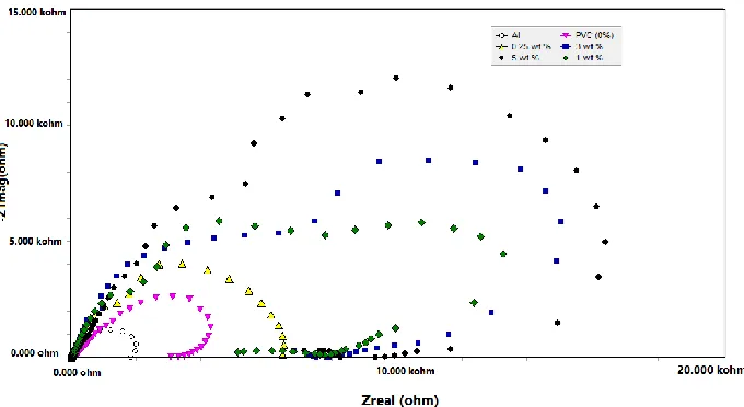
The electrochemical impedance spectroscopy curves for the aluminium electrode coated with PVC nanofiber and ceria doped insitu within PVC nanofiber in 0.1 M HCl at 25 ± 2o
[image:7.596.65.534.575.761.2]C, are shown in Figure 4. As shown in figure there is an increase in the diameter of capacitive loop, with the increased concentration of ceria in PVC solution, which indicate that the corrosion resistance of aluminum increases gradually.This increasing in diameter is due to the high frequency of the capacitive loop which can accomplished with charging transfer reactions, and leads to formation of partial double layer capacitance on the alumium surface and that explains increasing of alumium resistance with increasing the diameter of capacitive loop.
3.3. Nanocomposite charcterization
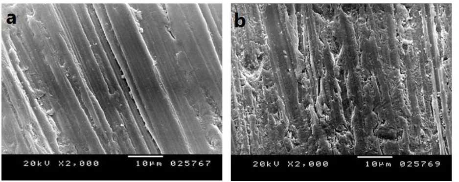
The morphology, structure, and the distribution of the PVC NFs on the coated surfaces were investigated using scanning electron microscopy (SEM) analysis. Aluminum, blank sample, PVC NFs and PVC NFs embedded in-situ ceria NPs with concentration 3 wt% coated on aluminum surface were examined by SEM before and after immersing in 0.1 M HCl for 24 hrs. (C.f Figure 5).By comparing original reference sample before and after the corrosion test it could be observed that the sample has been corroded, and the grooves’ contrast (depth) is not as visible as before the test as it is covered, and hidden by corrosion-produced compounds. This leads to the conclusion that hydrochloric solution has reached the whole surface including the bottom of the grooves [25].
SEM micrographs of PVC NFs, and PVC NFs embedded in-situ ceria NPs coated samples before and after the immersing in HCl clears that there is not a significant change in the surface appearance. The average mean diameter of PVC NFs is found to be about 620 nm, and mean diameter of PVC NFs embedded in-situ ceria NPs with concentration 3 wt% is found to be about 486 nm.
Figure 5. SEM images of the reference sample (Al) a) before and b) after immersion in 0.1 M HCl, PVC NFs coated on aluminum surface c) before and d) after immersion in 0.1 M HCl, PVC NFs embedded in-situ ceria NPs with concentration 3 wt% coated on aluminum surface e) before and f) after immersion in 0.1 M HCl.
[image:8.596.66.533.67.440.2] [image:8.596.137.457.539.740.2]
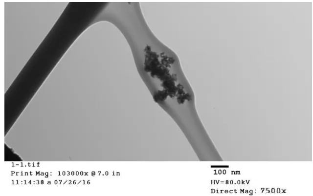
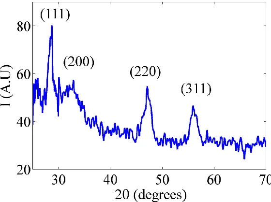
The crystalline structure of the doped nanoparticles is mainly composed of ceria NPs from the first diffraction peak of the most stable surface plane of ceria; (111) plane, the mean diameter is confirmed to be about 6 nm using Scherer’s formula [28, 29].
(2)
[image:9.596.93.493.200.356.2]Where is the average particle size diameter, is the wavelength of X-ray, is the full width half-maximum (FWHM) of the surface plane pattern, and is the diffraction angle.
Figure 7. TEM image of ceria NPs with mean grain size 6 nm.
Figure 8. XRD pattern of ceria NPs
3.4. Optical characterization of ceria NPs embedded in-situ with PVC nanofibers
[image:9.596.158.438.400.609.2]
2 1
) (
)
(E A EEg
(3)
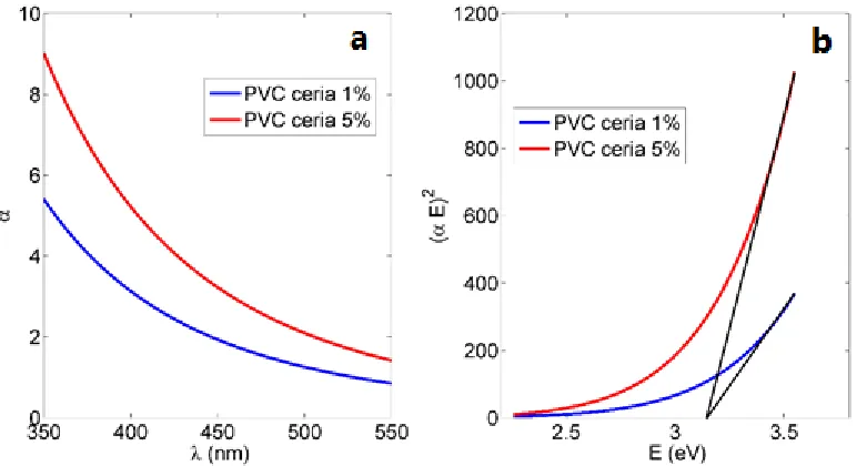
where α is the absorbance coefficient, A is a constant that depends on the effective masses of electrons, and holes in ceria NPs, E is the absorbed photon energy, and Eg is the allowed direct band
gap. Figure 9.b shows the relation between (αE) 2 versus E, and the intersection of the extrapolation of the linear part of (αE) 2
curve with E (x-axis) is equal to allowed direct bandgap Eg that particular
[image:10.596.99.485.206.416.2]composition of ceria NPs with moderate concentration of tri-valent cerium ionization states with associated O-vacancies, which is within accepted range raised to 3 eV [31, 32]
Figure 9. PVC NFs with in-situ embedded ceria NPs a) Absorbance curve b) Band gap curve
Figure 10. Fluorescence intensity PVC NFs with in-situ embedded different concentrations ceria NPs
[image:10.596.119.477.475.669.2]
emission appears at wavelength approximately equals to 520nm. Since PVC NFs only are considered as a non-optical material, this optical fluorescence emission is as a result of the embedded ceria NPs [32].
4. CONCLUSIONS
The effect of PVC coatings on the corrosion behavior of aluminum 0.1 M HCl solutions was examined using cyclic potentiodynamic polarization (CPP) ,and electrochemical impedance spectroscopy (EIS) measurements. The surface morphologies of the formed nanofiber coatings before and after immersing in HCl for 24 hrs. are characterized using scanning electron microscopy (SEM) and the mean diameter of ceria NPs was examined using TEM analysis. The bandgap for ceria nanoparticles in all synthesized nanofibers was around 3.5 V; which indicates that it is still optically active [32]. Cyclic potentiodynamic polarization measurements show that coating the metal surface with PVC NFS reduces both corrosion currents, and corrosion rates, and increases the polarization resistances compared to uncoated surface.The results also illustrated as ceria concentration in PVC nanofiber increases, the corrosion rate decreases. EIS spectra confirmed that the ceria NPs doped PVC coated surfaces provided semicircles with bigger diameters; which indicates that these surfaces are more passivated. All measurements proved that coating the metal surface with PVC coating can protect to a great extent the aluminum against corrosion in 0.1 M HCl solution.
Abbreviations:
Ceria NPs: cerium oxide nanoparticles. PVC: Poly-vinyl chloride.
SEM: Scanning Electron Microscope. TEM: Transmission Electron Microscope.
References
1. J. Yue and Y. Cao, Int. J. Electrochem. Sci., 10 (2015) 5222.
2. A. Fouda, M. Abdallah, I. Ahmed and M. Eissa, Arab. J. Chem, 5 (2012) 297. 3. G. Elewady, I. El-Said and A. Fouda, Int. J. Electrochem. Sci., 3 (2008) 177.
4. J. E. Field and Trane, CORROSION OF ALUMINUM-FIN, COPPER-TUBE HEAT EXCHANGE COILS, Proceedings of the Thirteenth Symposium on Improving Building Systems in Hot and Humid Climates, Houston, TX, 2002,20 .
5. R. Hassan, I. Zaafarany, A.Gobouri and H. Takagi,Int. J. Corros., 6 (2013) 0.
6. M.Es-saheb, A. Elzatahry, E. Sherif, A Alkaraki and E. kenawy, Int. J. Electrochem. Sci., 7 (2012) 5962.
7. L. Molina-Ocampo, M .Valladares-Cisneros and J. Gonzalez-Rodriguez,Int. J. Electrochem. Sci., 10 (2015) 383.
9. R. Hassan and I. Zaafarany, Mater. Sci, 6 (2013) 2436.
10.A. Fouda, K. Shalabi and N. Mohamed,Int. J. Innov. Res. Sci.., 3 (2014) 2319. 11.Q. Zhang and Y. Hua, Mater. Chem. Phys., 119 (2010) 57.
12.B. Hinton, D. Arnott and N. Ryan, Met. Forum J., 7 (1984) 211. 13.H. D. Johansen, C. Brett and A. Motheo, Corros. Sci, 63 (2012) 342.
14.I. Kartsonakis, E. Koumoulos, A .Balaskas, G. Pappas, C. Charitidis and G. Kordas, Corros. Sci, 57 (2012) 56.
15.N. Shehata, E. Samir, S. Gaballah, A. Hamed and A. Elrasheedy, Sensors,16 (2016) 1371. 16. S. Agarwal, J. Wendorff and A. Greiner, Polymers (Basel, Switz.), 49 (2008) 5603.
17.S. Sell, P. Wolfe , K. Garg , J. McCool , I. A. Rodriguez and G. Bowlin, Polymers (Basel, Switz.) 2 (2010) 522.
18. B. Ding, M. Wang, J. Yu, G. Sun, Sensors, 9 (2009)1609.
19.A. Luzio, E. V. Canesi, C. Bertarelli and M. Caironi, Mater. Sci., 7 (2014) 906.
20.M. Es-saheb, E. Sherif, A. El-Zatahry, M. El Rayes and K. A. Khalil, Int. J. Electrochem. Sci., 7 (2012) 10442.
21. E. M. Sherif , M. Es-saheb, A. El-Zatahry , E. kenawy and A. Alkaraki, Int. J. Electrochem. Sci., 7 (2012) 6154.
22.N, Shehata, E. Samir and S. Gaballah, Sens. Actuators, B, 231 (2016) 341.
23.N. Shehata, K. Meehan, M. Hudait, N. Jain and S. Gaballah, Nanomaterials, 5 (2014) 1. 24.H. Chen and H. Chang Colloids Surf. A, 242(2014) 61.
25.A. Toloei, V. Stoilov and D. Northwood, Mater. Charact. , 77 (2013) 193.
26. A. Al-Amiery, A. Kadhum, A. Mohamad, A. Musa and C. Li, Mater. Sci., 6 (2013) 5466. 27.W.li, Q.He, S. Zhang and C. Pei, J. Appl. Electrochem., 38 (2008) 289.
28.S. Deshpande, S. Patil, S. Kuchibhatla and S. Seal, Appl. Phys. Lett., 87 (2015) 1.
29.B. D. Cullity and S. R. Stock, Elements of x-ray diffraction, Addison-Wesley Publisher (2001) Boston,United States
30.J. I. Pankove, Optical processes in semiconductors, Dover Publications, (1971)United States, New York.
31.E. Goharshadi, S. Samiee and P. Nancarrow, Adv. Colloid Interface Sci., 356 (2011) 474. 32.N. Shehata, K Meehan, M. Hudait and M. Jai, J. Nanopart., 14 (2012) 1173.