Int. J. Electrochem. Sci., 13 (2018) 3080 – 3090, doi: 10.20964/2018.03.04
International Journal of
ELECTROCHEMICAL
SCIENCE
www.electrochemsci.orgShort Communication
Development and Performance of an All-Solid-Stated pH Sensor
Based on Modified Membranes
Kun Xu1, 2,Xiliang Zhang2,*, Cheng Chen2 and Miaomiao Geng2
1
College of Electrical Engineering, Henan University of Technology, Zhengzhou 450001, China;
2
School of Mechanical Engineering, Jiangsu University, Zhenjiang 212013, China
*
E-mail: [email protected], [email protected]
Received: 15 October 2017 / Accepted: 17 December 2017 / Published: 5 February 2018
In this study, we developed an all-solid-stated planar pH sensor with the help of magnetron sputtering technology and printed circuit board (PCB). The developed pH sensor consists of a working electrode, which employed antimony sensitive thin film and Nafion modification membrane, and an Ag/AgCl reference electrode, which was modified by graphene-chitosan membrane. Then, the performance of the pH sensor was investigated. The results demonstrate that the developed pH sensor has excellent features, including high sensitivity (54.5 mV/pH in the pH range from 4 to 9), short response time (about 20 s), and stability (less than 2 mV in 10 min period, and less than 2 mV/pH in a month.). Further, the developed pH sensor was applied in some common samples, such as coke, vinegar, mineral water, clay, peat, and vermiculite, and the measuring absolute error was less than 0.60 units, and the measuring relative error was about 10%. The pH sensor is low cost, high performance, and easy fabrication, is promising to popularize in laboratory and industrial.
Keywords: pH sensor; all-solid-stated; antimony film; Ag/AgCl reference electrode; modification
1. INTRODUCTION
For optical pH sensors, fluorescent pH sensor was one of important pH sensor due to its high sensitivity, specificity, high signal-to-noise ratio and minimal damage to living samples[6]. On basis of the fluorescent pH sensor, some new functional materials were founded and employed, such as indeno-furan[6], 1-aminoperylene bisimides covalently grafted onto poly(acryloylmorpholine)[7], indenoquinoline dione conjugate[8], rhodamines[9], tricyclic cytosine analogue [10], silicon nanoparticles (SiNPs) with pH-sensitive dopamine [11], ion-pair of 8-hydroxypyrene-1,3,6-trisulfonic acid trisodium salt (HPTS) and hexadecyltrimethylammonium bromide (CTAB) [2], CdSe/ZnS quantum dot [12], and so on.
For field-effect transistors, ion-sensitive field-effect transistor was another important solution of pH measurement, and many relative studies were reported recently. An extended gate field-effect transistor (EGFET) pH sensor was prepared based on porous silicon, which has a sensitivity value of 66 mV/pH[13]. In 2013, several researchers presented a pH sensor composed of a double-gate silicon nanowire field-effect transistor (DG Si-NW FET)[14]. A new field effect transistor (FET) with a suspended gate was proposed as sensing part, which has a high sensitivity (about 300mV/pH) to pH measurement in microfluidic channel [15]. -Ga2O3 nanowires was prepared for extended gate field effect transistor (EGFET) as a pH sensor[16], as well as ZnO nanowire [17], and CuO nanowire [18]. The carbon-nanotube thin film was demonstrated as pH sensing membrane, and continuous-wave laser was employed to improve pH sensitivity [19]. The zinc oxide thin-film and nanorod arrays also were demonstrated as pH sensing membrane in EGFET [20].
With the development of the materials science, more and more new functional materials were found and employed in pH sensors. A new solid-state pH sensor based on a carbon paste electrode incorporated with sulfate-modified nanosized -Fe2O3 was reported, which gave response time of approximately 10 s[21]. A compact, robust and cost effective impedimetric pH sensor was presented, which consists of parallel coplanar electrodes of aluminum coated with Molybdenum disulfide (MoS2) nanoparticles and Nafion as permselective layer[22]. A new voltammetric pH sensor based on glassy carbon electrode which incorporating poly-dopamine thin film was developed for water industry[23]. The resistance-based pH sensing capability of ZnO nanorods was presented, and the least electrode width has higher sensitivity [24].
For potentiometric pH sensors, metal/metal oxide electrodes have been reported for pH measurement due to important advantages, such as mechanical strength, manufacturing technology, and electrochemical stability. Many different solid-state metal oxides were demonstrated as pH sensing materials, such as Ti/TiO2, Zr/ZrO2, W/WO3, Ir/IrO2, Sb/Sb2O3, Ru/RuO2, and Pd/PdO [25]. A planar pH sensor based on screen-printed sub-micron Cu2O-doped RuO2 film was reported, and the influence of thickness of the sensing film has been investigated [26, 27]. A tantalum pentoxide (Ta2O5) based electrolyte-ion sensitive membrane-oxide-semiconductor pH sensor was developed and investigated, which was for acidic environment[28]. Iridium oxide was also employed as pH sensing thin film for pH sensor due to good stability in a wide pH range [29, 30]. Likewise, pH sensor based on TiO2 sensitive thick film was fabricated and its electrochemical characteristics were performed [31].
is very complicated, and it presents a high demand on manufacturing technology. For pH sensors based on new materials, the reproducibility is controversial. Comparing with these three solutions, the potentiometric pH sensors, especially metal/metal oxide pH sensor, has many merits, such as easy fabrication, low cost, good mechanical properties, and so on.
In this study, we developed an all-solid-stated planar pH sensor with the help of magnetron sputtering technology and printed circuit board (PCB). The developed pH sensor consists of a working electrode, which employed antimony sensitive thin film and Nafion modification membrane, and a Ag/AgCl reference electrode, which was modified by graphene-chitosan membrane. Then, the performance of the pH sensor was investigated. The results demonstrate that the developed pH sensor has excellent features, including high sensitivity, short response time, and stability. Further, the developed pH sensor was applied in some common samples, such as coke, vinegar, mineral water, clay, peat, and vermiculite, and the measuring absolute error was less than 0.60 units, and the measuring relative error was about 10%.
2. EXPERIMENTAL DETAILS 2.1 Reagents and apparatus
Nafion solution (D520, 5 wt%) was purchased from Dupont China Holding Co., Ltd. Graphene was purchased from Nanjing XFNANO Materials Tech Co., Ltd (Nanjing, China). Chitosan and other reagents were obtained from Sinopharm Chemical Reagent Co., Ltd (Shanghai, China). All reagents were of analytical grade. All aqueous solutions were prepared with deionized (DI) water. The chitosan-graphene dispersion (0.5 mg/mL, w/v) was prepared by adding 1 mg graphene into 2 mL chitosan solution, and then continuously ultrasonic dispersed for 30 min at room temperature. Deionized water used for the solutions was purified by the Milli-Q system (≥18 M, Millipore).
2.2 Fabrication of the pH sensor
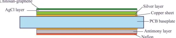
The all-solid-state pH sensor consists of working electrode, reference electrode, and PCB, as shown in Fig. 1. The working electrode and reference electrode are placed in two sides of the PCB, and copper substrates are determined as conducting layer. In this work, the antimony is determined as pH sensing material, and Nafion is chosen as modification membrane[25]. Also, the Ag/AgCl electrode is selected as reference electrode, and graphene-chitosan is determined as modification.
[image:3.596.155.443.663.725.2]
As to the working electrode, its structure was shown in Fig.2. Firstly, with the help of the ultra-high vacuum magnetron sputtering coater (JS3X-100B,Werner Technology Co. Ltd, China), the Sb sensitive film was deposited. The deposition process parameters are listed in Table 1. Note that the Sb films were not treated by heating. Then, the Nafion membrane was coated on the Sb thin film by drop casting. Concretely speaking, the Nafion membrane was fabricated by 5 wt% Nafion solution (DuPont, China) diluted with anhydrous alcohol. The membrane was dried at 60C for 2 h in vacuum to remove the majority of solvent, and then dried at 80C for another 2 h to enhance the mechanical performance. The drop casting was repeated 3 times. With the ultra-high resolution field emission scanning electron microscopy (FESEM, MERLIN Compact, Carl ZEISS, Germany), the thickness of the Sb thin film and Nafion membrane were measured, and the results are 255 nm and 1.6 m, respectively. The image of the cross-sectional view was shown in Fig. 3.
Figure 2. Schematic of the working electrode (a)top view; (b)sectional view[25].
Table 1. Sputtering parameters for Sb sensing film deposition
Category Settings
Target Sb (99.99% pure)
Process gas Ar
Flow 39 sccm
Substrate temperature Room temperature
Vacuum 310-4 Pa
Sputtering power 65 W
Process pressure 1 Pa
Target size 1005 mm (cylindrical)
Process time 45 min
[image:4.596.178.417.275.349.2] [image:4.596.177.420.443.650.2]
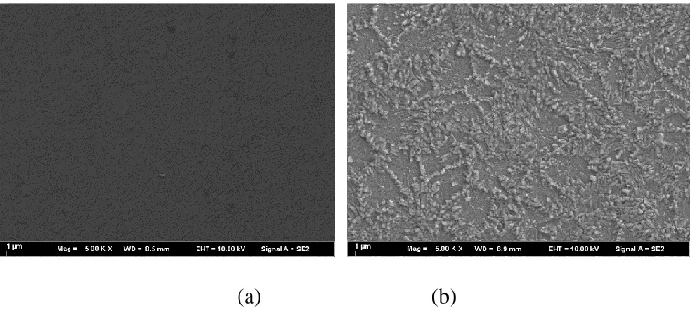
As to the Ag/AgCl reference electrode, the procedure of the fabrication was shown in Fig. 4. Firstly, the Ag thin film was prepared by magnetron sputtering on copper substrates inlaying in commercial printed circuit board (PCB). The deposition process parameters that were used to fabricate the Ag thin film were listed in Table 2. The deposited Ag thin films are not treated by heating. The thickness was measured and that was 4.2 m. After that, the resulting Ag electrode was immersed in a sodium hypochlorite solution (NaClO, 2 wt%) 30 s to form an AgCl layer, which was then cleaned with deionized water. The Ag/AgCl electrode was activated in saturated AgCl solution for 4 h in dark. With the ultra-high resolution field emission scanning electron microscopy, the surface morphology was studied subsequently, and the results are shown in following Fig. 5.
Figure 4. Schematic drawing of the whole fabrication process
(a) (b)
Figure 5. SEM image of thin film before and after chlorination. Image (a) and (b) show the surface morphology of the thin film before and after chlorination (the magnification of the images is 5 k).
[image:5.596.175.418.249.387.2] [image:5.596.110.488.432.601.2]
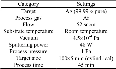
Table 2. Sputtering parameters for Ag thin film deposition
Category Settings
Target Ag (99.99% pure)
Process gas Ar
Flow 52 sccm
Substrate temperature Room temperature Vacuum 4.510-4 Pa
Sputtering power 48 W
Process pressure 1 Pa
Target size 1005 mm (cylindrical)
Process time 45 min
2.3 pH measurement
All electrochemical experiments were carried out with an electrochemical workstation (CHI660, Shanghai ChenHua Instruments, China). The standard pH buffer solutions were applied to determine the pH sensor’s performance. The pH value of these pH buffer solutions were validated with a commercial pH glass-electrode sensor (Basic pH Meter PB-10, Sartorius, Germany) before every test. After every test, the sensors were cleaned by deionized water and dried in N2 atmosphere. A
magnetic stirrer was used to continuously stir the best solutions for quicker equilibrium of ion concentrations around the sensor.
3. RESULTS AND DISCUSSION 3.1 Sensitivity
In this work, the sensitivity of the pH sensor was determined in pH buffer solutions of pH 4.01, 5.42, 6.86, 8.37 and 9.18 at 25C. The electrochemical workstation was used for recording, and the stable output was considered as the measured value. Every measurement was repeated three times and the mean value was taken. The results were shown in Fig. 6.
In Fig. 6, it is obviously that the markers showed a good linear relationship. After linearization regression analysis, the equation of the line was
0.144 0.0545
E pH
It also can be derived to the equation as following
0.144-0.0545
E pH
Figure 6. Measured potential versus pH value for the pH sensor
3.2 Response time
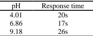
[image:7.596.154.446.74.259.2]In general, the response time was defined as the time of sensor’s output reach to 90% of the equilibration after the measurement was started, especially to electrochemical sensors [25, 32, 33]. Concretely speaking, the response time of the pH sensor was the transient time of the sensor’s output voltage reach to 90% of the equilibrating voltage after immersing the sensor in sample solutions. To estimate the response time of the developed pH sensor, the sensor was immersed in standard pH buffer solutions whose pH values were 4.01, 6.86, and 9.18, respectively. The electrochemical workstation was used to record the output of the sensor, and the response times were obtained with the records. Every experiment was repeated three times, and the average response time showed as Table 3. In Table 3, the response time of the developed pH sensor was about 20 s, and in near neutral solution, the response time was shorter than that in acid solution and alkaline solution.
Table 3. Response time of the pH sensor in different pH buffer solutions
pH Response time
4.01 20s
6.86 17s
9.18 26s
3.3 Stability
[image:7.596.221.375.553.613.2]
Figure 7. Stability of the developed pH sensor
Further, the relative statistical analysis was employed in this study. The analysis results showed that the standard deviation of the measured output potential in pH 4.01 standard buffer solution was 1.5 mV, and less than 1 mV in pH 6.86 standard buffer solution, and 1.8 mV in pH 9.18 standard buffer solution. That’s to say, the standard deviations in all three solutions were less than 2 mV in 10 min period.
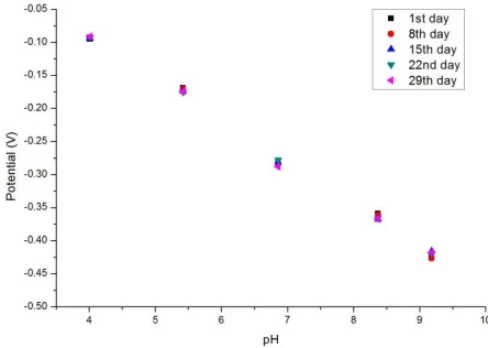
Also the stability of the developed pH sensor was studied in a long period. As the previous experiments, the pH buffer solutions which pH values were 4.01, 6.86, and 9.18 respectively were selected as the measuring object. In a month, the pH values of these solutions were measured every a week by the developed pH sensor, and the equilibration potentials were recorded. Every measurement was repeated three times in one day, and the mean value of the equilibration potential was taken and shown in Fig. 8.
[image:8.596.187.412.76.250.2]Through the Fig. 8, the sensitivities of the developed pH sensor in every measurement were obtained by linear fitting. The sensitivities were 54.5 mV/pH, 55.8 mV/pH, 56.4 mV/pH, 55.5 mV/pH, and 56.2 mV/pH in the 1st day, 8th day, 15th day, 22nd day, and 29th day in a month. The maximal deviation of the sensitivity was less than 2 mV/pH.
[image:8.596.188.410.567.725.2]
There are many publications has presented pH sensors, especially with magnetron sputtering [25].For example, Xu et al. had presented a pH sensor with RuO2/carbon nanotubes electrodes deposited by magnetron sputtering, which sensitivity was 55 mV/pH, response time was 40 s, and the potential drift was 2.3 mV/pH[34]. For another example, Liao et al. had reported a pH sensor obtained by RF sputtering, which sensitivity was 55.64 mV/pH, potential drift was 0.38 mV/h[35]. Comparison of the performance of the pH sensor reported by other scientists, it is obviously that the developed pH sensor has a better or similar behavior.
3.4 Experiments for soil/soilless cultural substrate
[image:9.596.105.491.415.683.2]In this section, the developed pH sensor was applied in some common samples, such as coke, vinegar, mineral water. Similar measurements were also completed in soil/soilless cultural substrates extractions, such as clay, peat, and vermiculite. The extractions were prepared by international standard method for soil pH measurement, which mass ratio of soil/water was 1:2.5. Three same samples were used and numbered 1, 2, 3, and 4. Before extraction, the samples (except the sample 1) were treated with different volume pH standard buffer solution (pH 4.01), and then oven dried to achieve constant weight.
Table 4. Results of the measurements
Category Output potential (V) pH measured value pH reference value Absolut e error Relative error (%)
Coke -0.0011 2.62 2.81 -0.19 -6.76
Vinegar -0.0423 3.41 3.52 -0.11 -3.13
Mineral
water -0.2173 6.75 6.84 -0.09 -1.32
Clay 1 -0.1851 6.14 6.43 -0.29 -4.51
Clay 2 -0.1365 5.21 5.65 -0.44 -7.79
Clay 3 -0.2238 6.88 6.75 0.13 1.93
Clay 4 -0.2379 7.15 7.51 -0.36 -4.79
Peat 1 -0.1668 5.79 5.45 0.34 6.24
Peat 2 -0.0847 4.22 4.82 -0.60 -12.45
Peat 3 -0.1741 5.93 6.29 -0.36 -5.72
Peat 4 -0.2677 7.72 8.15 -0.43 -5.28
Vermiculite 1 -0.2303 7.01 7.48 -0.47 -6.28
Vermiculite 2 -0.1401 5.28 5.86 -0.58 -9.91
Vermiculite 3 -0.2076 6.57 7.13 -0.56 -7.85
Vermiculite 4 -0.2819 7.99 8.61 -0.62 -7.21
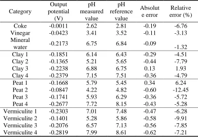
As shown in Table 4, the maximum absolute error of the developed pH sensor to the digital pH meter was -0.19 unit in solution samples, and the maximum relative error was -6.76%. The maximum absolute error in clay extraction samples was -0.44 units, and the maximum relative error was -7.79%. The maximum absolute error in peat extraction samples was -0.60 units, and the maximum relative error was -12.45%. The maximum absolute error in vermiculite extraction samples was -0.62 units, and the maximum relative error was -9.91%. From above analysis, in general, the maximum absolute error was about 0.60 units, and the relative error was about 10%.
According to the Table 4, it is obviously that the error in solution samples is less than that in soil/soilless cultural substrates. Furthermore, as to soil/soilless cultural substrates, the error in clay is less than that in peat, and the error in peat is less than that in vermiculite. The other finding is that the error in acid conditions is larger than that in other conditions. In this study, the chitosan-graphene was determined as the modification. However, in acid conditions, the chitosan will be dissolved a little, so the reference potential of the Ag/AgCl reference electrode will be drifted a little, which leads to a larger error.
4. CONCLUSIONS
In this study, we developed an all-solid-stated planar pH sensor with the help of magnetron sputtering technology and printed circuit board (PCB). The developed pH sensor consists of a working electrode, which employed antimony sensitive thin film and Nafion modification membrane, and an Ag/AgCl reference electrode, which was modified by graphene-chitosan membrane. Then, the performance of the pH sensor was investigated. The sensitivity of the developed pH sensor was 54.5 mV/pH, the response time was about 20 s, the standard deviations were less than 2 mV in 10 min period, and in a month the maximal deviation of the sensitivity was less than 2 mV/pH. The results demonstrate that the developed pH sensor has excellent features, including high sensitivity, short response time, and stability. Further, the developed pH sensor was applied in some common samples, such as coke, vinegar, mineral water, clay, peat, and vermiculite, and the measuring absolute error was less than 0.60 units, and the measuring relative error was about 10%.
ACKNOWLEDGMENTS
This work was partly supported by the National Key Technology R&D Program of China (grant number 2014BAD08B04).
References
1. M. Cao, S.K. Mahto, O. Yadid-Pecht, Ieee Sens. J., 16 (2016) 3611.
2. Q. Cui, O. Podrazky, J. Mrazek, J. Probostova, I. Kasik, Ieee Sens. J., 15 (2015) 4967. 3. P. Fanzio, C.-T. Chang, M. Skolimowski, S. Tanzi, L. Sasso, Sensors, 17 (2017)1169. 4. D. Wencel, T. Abel, C. McDonagh, Anal. Chem., 86 (2014) 15.
7. D. Aigner, S.M. Borisov, P. Petritsch, I. Klimant, Chem. Commun., 49 (2013) 2139. 8. K. Aggarwal, J.M. Khurana, J. Lumin., 187 (2017) 457.
9. D. Aigner, S.M. Borisov, F.J. Orriach Fernandez, J.F. Fernandez Sanchez, R. Saf, I. Klimant, Talanta, 99 (2012) 194.
10. P. Bielecka, B. Juskowiak, Molecules, 20 (2015) 18511.
11. B. Chu, H. Wang, B. Song, F. Peng, Y. Su, Y. He, Anal. Chem., 88 (2016) 9235. 12. F. Zhao, I. Kim, J. Kim, J. Nanosci. Nanotechno., 14 (2014) 5650.
13. N.H. Al-Hardan, M.A.A. Hamid, N.M. Ahmed, A. Jalar, R. Shamsudin, N.K. Othman, L.K. Keng, W. Chiu, H.N. Al-Rawi, Sensors, 16 (2016)839.
14. J.-H. Ahn, J.-Y. Kim, M.-L. Seol, D.J. Baek, Z. Guo, C.-H. Kim, S.-J. Choi, Y.-K. Choi, Appl. Phys. Lett., 102 (2013)70.
15. I. Bouhadda, O. De Sagazan, F. Le Bihan, Microsyst. Technol., 21 (2015) 289. 16. S.-P. Chang, K.-J. Chen, Nanosci. Nanotech. Let., 6 (2014) 914.
17. S.-P. Chang, C.-W. Li, K.-J. Chen, S.-J. Chang, C.-L. Hsu, T.-J. Hsueh, H.-T. Hsueh, Sci. Adv. Mater., 4 (2012) 1174.
18. S.-P. Chang, T.-H. Yang, Int. J. Electrochem. Sci., 7 (2012) 5020.
19. Y.-S. Chien, W.-L. Tsai, I.C. Lee, J.-C. Chou, H.-C. Cheng, Ieee Electr. Device L., 33 (2012) 1622. 20. Y.-S. Chiu, C.-Y. Tseng, C.-T. Lee, Ieee Sens. J., 12 (2012) 930.
21. T. Alizadeh, F. Jamshidi, J.Solid State Electr., 19 (2015) 1053.
22. P. Awasthij, R. Mukherjee, S.P.O. Kare, S. Das, RSC Adv., 6 (2016) 102088.
23. M. Amiri, E. Amali, A. Nematollahzadeh, H. Salehniya, Sens. Actuators B, 228 (2016) 53.
24. V.C. Copa, A.R. Tuico, J.P. Mendoza, J.P.R. Ferrolino, C.J.T. Vergara, A.A. Salvador, E.S. Estacio, A.S. Somintac, J. Nanosci. Nanotechno., 16 (2016) 6102.
25. K. Xu, X. Zhang, K. Hou, M. Geng, L. Zhao, J. Electroche. Soc., 163 (2016) B417.
26. S. Zhuiykov, E. Kats, K. Kalantar-zadeh, M. Breedon, N. Miura, Mater. Lett., 75 (2012) 165. 27. S. Zhuiykov, E. Kats, Ionics, 18 (2012) 797.
28. M. Chen, Y. Jin, X. Qu, Q. Jin, J. Zhao, Sens. Actuators B, 192 (2014) 399. 29. J. Yu, M. Khalil, N. Liu, R. Lee, Ionics, 21 (2015) 855.
30. N. Uria, N. Abramova, A. Bratov, F.-X. Munoz-Pascual, E. Baldrich, Talanta, 147 (2016) 364. 31. M. Simic, L. Manjakkal, K. Zaraska, G.M. Stojanovic, R. Dahiya, Ieee Sens. J., 17 (2017) 248. 32. S. Yao, M. Wang, M. Madou, J. Electrochem. Soc., 148 (2001) H29.
33. W.-D. Huang, H. Cao, S. Deb, M. Chiao, J.C. Chiao, Sens. Actuators A, 169 (2011) 1. 34. B. Xu, W.-D. Zhang, Electrochimica Acta, 55 (2010) 2859.
35. Y.-H. Liao, J.-C. Chou, Sens. Actuators B, 128 (2008) 603.
![Figure 2. Schematic of the working electrode (a)top view; (b)sectional view[25].](https://thumb-us.123doks.com/thumbv2/123dok_us/1784060.132604/4.596.177.420.443.650/figure-schematic-working-electrode-view-b-sectional-view.webp)