processing.
.
White Rose Research Online URL for this paper:
http://eprints.whiterose.ac.uk/143675/
Version: Published Version
Article:
Hernández-Nava, E. orcid.org/0000-0002-6414-3313, Mahoney, P., Smith, C.J. et al. (3
more authors) (2019) Additive manufacturing titanium components with isotropic or graded
properties by hybrid electron beam melting/hot isostatic pressing powder processing.
Scientific Reports, 9. 4070. ISSN 2045-2322
https://doi.org/10.1038/s41598-019-40722-3
[email protected]
https://eprints.whiterose.ac.uk/
Reuse
This article is distributed under the terms of the Creative Commons Attribution (CC BY) licence. This licence
allows you to distribute, remix, tweak, and build upon the work, even commercially, as long as you credit the
authors for the original work. More information and the full terms of the licence here:
https://creativecommons.org/licenses/
Takedown
If you consider content in White Rose Research Online to be in breach of UK law, please notify us by
components with isotropic or
graded properties by hybrid
electron beam melting/hot isostatic
pressing powder processing
E. Hernández-Nava , P. Mahoney , C. J. Smith , J. Donoghue , I. Todd &
S. Tammas-Williams
A methodology has been demonstrated to consolidate Ti Al V powder without taking it to the
liquid state by novel combination of the electron beam melting additive manufacture and hot isostatic pressing processes. This results in improved static mechanical properties (both strength and yield) in comparison to standard EBM processed material. In addition, the ability to generate microstructurally
graded components has been demonstrated by generating a component with a signi cant change in both microstructure and mechanical properties This is revealed by the use of electron backscattered di raction and micro hardness testing to produce maps showing a clear distinction between materials consolidated in di erent ways The variation in microstructure and mechanical properties is attributed to the di erent thermal history experienced by the material at di erent locations In particular it is found that the rapid cooling experienced during EBM leads to a typical ne α lath structure, whereas a more equiaxed α grains generated by di usion is found in HIP consolidated powder
Additive manufacturing (AM) has had a signiicant impact on metallurgical research in both academia and industry in recent years1–3. A wide range of AM techniques have become available and are united by the basic
principles of depositing material layer by layer to produce components1. he advantages of AM are well
docu-mented in the literature1,2, so an exhaustive list is not provided here. For producing new parts with high spatial
resolution, powder bed fusion (PBF) is commonly applied. PBF-AM involves layers of powder spread by a rake or wiper, which are then melted with a laser or electron beam into the geometry deined by a sliced CAD model.
Unfortunately, AM and PBF are not without drawbacks, not least their relatively slow deposition speeds and higher costs per unit manufactured compared to established manufacturing routes. Another issue is the surface inish of components, which is generally too poor for them to be used without some kind of inishing operation to reduce the surface roughness4. In addition, many alloys, when processed by standard AM melt strategies, have a
microstructure dominated by columnar grains that grow through multiple layers5,6. Unsurprisingly, this can lead
to anisotropic mechanical static and dynamic properties7. he inal key drawback for PBF-AM is the potential for
porosity formation. Porosity can be generated during PBF from a range of sources depending on the line energy of the heat source, ranging from simple lack of fusion between particles, to keyhole pores8. For example, keyhole
porosity resulting from the vaporisation of low melting point elements in prealloyed powder9, has been reported
to decrease the mechanical properties of AM components10. In addition, gas trapped within the powder feedstock
can be retained within the consolidated material11. All pores act as stress concentrators, and the fatigue
perfor-mance of material can be strongly inluenced by their location and size12. Even more detrimental features such
as cracks can result if the parameters are not optimised for the material being processed13. he high local cooling
rates experienced during AM mean that most AM processes tend to produce parts with large residual stresses that must be heat treated prior to being put into service7.
Department of Materials Science and Engineering University of Sheffield Sheffield S JD UK School of
Materials University of Manchester Manchester M PL UK Department of Maritime and Mechanical
Engineering Liverpool John Moores University Liverpool L AF UK Correspondence and requests for materials should be addressed to E H N email e hernandeznava she eld ac uk)
Received: 2 October 2018
Accepted: 20 February 2019
One particular PBF technology, electron beam melting (EBM), minimises residual stresses by conducting the entire manufacturing cycle at an elevated temperature. Arcam AB (Gothenburg, Sweden) are currently the only suppliers of EBM equipment, and use proprietary sotware and a thermal model to maintain an elevated powder bed temperature throughout the build. Prior to melting each layer of powder, the electron beam is defocused and swept across the bed at a high speed. his both preheats and partially sinters the powder14. he sintering is necessary to
avoid the build-up of negative charge where the electron beam interacts with the powder. By varying the level of pre-heat the bed temperature is controlled by the sotware. For Ti-6Al-4V the intention is to maintain the bed at 650 °C, which is high enough to reduce the residual stresses in built parts to near zero15. his removes the need for a stress
relief heat treatment following manufacture, typically required for selective laser melted (SLM) parts.
In an attempt to avoid pores impacting the mechanical property of AM components, parts are oten subjected to a hot isostatic pressing (HIPing) cycle prior to being put into service. he application of high temperatures and pressures causes pores to collapse and the newly contacting surfaces to bond by difusion16. However, a
concur-rent coarsening of the microstructure leads to a reduction in yield strength of the material17.
To overcome some of the disadvantages of PBF-AM listed above, a hybrid approach to manufacturing has been proposed and demonstrated for SLM18–20. In particular, using SLM to generate a hollow preform before
ill-ing with powder and HIPill-ing to consolidate the particles. Reducill-ing the melt volume required leads to a commen-surate decrease in build time for the AM process, enhancing its commercial viability. In addition, the columnar microstructure associated with melting and solidiication can be avoided. hus, two issues with AM have been at least partially addressed, the directional microstructure, and the high cost of manufacture.
While these beneits alone make the proposed method worthwhile of further exploration, other advantages may result in even greater possible positive outcomes. Particularly, the ability of the technique to generate mate-rial with site-speciic properties and microstructures. By changing the properties with position, more eicient engineering structures could be generated than is currently possible21. For example, EBM has been used to
gener-ate lattice structures, where via spatial alteration of the lattice size and morphology, mgener-aterials with better fatigue strength and energy absorption than standard uniform lattice structures, were achieved22.
In this paper, we report on how this hybrid approach to manufacturing can be applied to EBM AM, and report the microstructure and mechanical properties of Ti-6Al-4V produced by this approach. hese are contrasted with Ti-6Al-4V manufactured by standard EBM techniques. Furthermore, we have demonstrated how it is possible to generate a microstructurally and mechanical property graded component by combining HIP and EBM.
Experimental Methods
All samples were manufactured using an Arcam A2, with some subjected to further HIP processing. The pre-alloyed Ti-6Al-4V powder used for this study had been recycled a number of times, but the chemical com-position remained within the allowable limits. he virgin powder was stated by the manufacturer to contain in weight percent: 6.45 Al; 3.94 V, etc., with powder batch number P1250. Over time it is likely that the oxygen level in the powder will increase. Chemical analysis of feedstock powder just prior to manufacture of the samples in the study showed oxygen content of 0.144 weight percent in accordance with ASTM F2924. Standard Arcam param-eters recommended for Ti-6Al-4V and a layer thickness of 50 µm were used to manufacture all samples. In brief, the Arcam EBM process is conducted in four stages. Prior to material deposition, the system was taken to a high vacuum before backilling with helium to a pressure of 2 × 10⁻³ mbar. As per standard Arcam operating
proce-dures, a stainless steel baseplate was preheated to 730 °C by rapidly scanning it with the electron beam at a high power and low focus. he temperature was measured using a thermocouple below and in contact with the 10 mm thick baseplate. hroughout the build the Arcam sotware will attempt to keep the energy input at the correct level to ensure that the build temperature remains at around 650 °C. he baseplate was incremented downwards (z) in steps of 50 µm and powder spread across it with a rake, which traverses in the horizontal (x) direction. Again, the beam was applied with a high speed, low focus and high power, this time to preheat and sinter the powder to increase its electrical and thermal conductivity14. he sintered powder could then be safely melted by
increas-ing the beam focus to produce small, rapidly movincreas-ing melt pools, which irst outlined the desired 2D geometry (termed contouring) before inilling the central areas (hatching). Standard Arcam recommended settings were used to manufacture all samples, and more detailed descriptions of the EBM process are available elsewhere11,23.
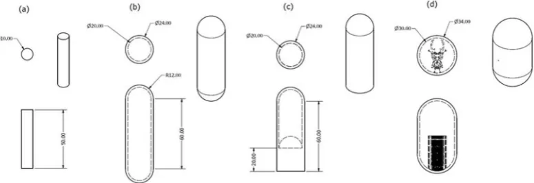
Samples were manufactured in order to examine both the properties of the material produced by the standard EBM process, both as built and ater HIP, and the EBM-HIP hybrid proposed here. Sixteen solid cylindrical spec-imens (geometry deined in Fig. 1a) were built to provide a baseline of standard EBM properties. Eight samples were orientated with their length aligned with the rake transverse (x) direction and eight with their length in the build (z) direction. he cylindrical samples in the horizontal direction were raised above the baseplate and used standard supports generated in Magics 20 (Materialise), whereas the vertical samples were built directly onto the baseplate. Four samples of each orientation were let in the as-deposited condition and four of each orientation were HIPed.
To examine properties of HIP consolidated powder, cylindrical capsules were built where only an outer 2 mm thick ‘skin’ was melted (Fig. 1b). he encapsulated powder remained in the as-sintered condition typical of the Arcam process. Again, samples were manufactured orientated in the build (z) and rake (x) direction. All samples were built ofset from the baseplate on supports automatically generated in Magics 20. A second set of capsules was manufactured with half of the internal area melted by the electron beam (Fig. 1c).
HIPing was conducted by Bodycote H.I.P. Ltd (Chesterield, United Kingdom) using the standard parameters developed to heal porosity in cast Ti-6Al-4V parts. his consisted of heating at 8.8 K/minute up to a 2-hour hold at 1193 K (920 °C) and 100 MPa, followed by cooling to room temperature at 7.8–8.5 K/minute.
To avoid repeated description of the various processing conditions experienced by diferent Ti-6Al-4V sam-ples, three designations will be used hereater. Ti-6Al-4V produced by standard Arcam EBM melt strategies is denoted EBM. Ti-6Al-4V that is irst melted during the EBM build but then subjected to the HIP cycle is labelled EBM-H. Finally, the encapsulated sintered powder consolidated during the HIPing is labelled EBS-H. When the interface between EBM-H and EBS-H (Fig. 1c) was tensile tested these samples are labelled EBM/S-H.
One of each of the geometries/orientations/conditions shown in Fig. 1a–c was retained for density determi-nation and hardness testing, whereas the other three samples were used to examine the tensile properties. Special Testing Ltd (Sheield, United Kingdom) machined and tested the material in accordance with ASTM A370 2017 using a 4 mm gauge diameter. Care was taken during tensile specimen machining of EBS-H samples to ensure that the outer 2 mm skin was removed to test only the consolidated powder within. Fractography of the broken tensile specimens was conducted with scanning electron microscopy (SEM) imaging using a FEI-Inspect F microscope with 15 kV of accelerating voltage, a spot size of 3 µm and a working distance of 10 mm.
For microstructural analysis and density determination planes normal to the longest length of each as built sample were prepared using standard metallurgical techniques to produce a mirror inish, in line with other work in the literature5. High resolution imaging of the grain morphology and EBSD analysis of the orientations
within the beetle capsule (Fig. 1d) was performed with a Zeiss Sigma SEM, whereas a lower resolution, but large area mapping was carried out with a TESCAN MIRA3. Imaging was carried out in backscattered electron mode to determine any microstructural variation between consolidation methods, and coarse scale EBSD was used to gather information about the crystallographic orientations and their distribution across the build. Two EBSD maps were gathered, using an Oxford Instruments NordlysNano EBSD detector paired with AZtec acquisition sotware. A larger map, with a 5 µm step size, was used to image an area of 25.3 mm by 9.3 mm, almost the entire cross section. A smaller, higher resolution map, an area of 5.5 mm by 4.2 mm with a 2.5 µm step size was used to calculate pole igures for the two diferent phases. EBSD analysis was carried out using HKL Channel 5, and the high temperature prior β microstructure calculated from the room temperature α orientation measurements using sotware developed at the University of Sheield by Davis and Wynne that utilises the Burger’s orientation relationship24.
For density determination, planes normal to the testing direction (Fig. 1a–c) were examined as polished, i.e. unetched. Optical micrographs were collected using an Olympus microscope equipped with Clemex sotware, which allows the stitching of multiple images to provide large, high-resolution images of each direction and condition. 36 images were taken of the central region of each sample at 200x magniication, resulting in a total imaged area of 10.9 mm2. he relative density of the specimens were quantiied by employing the Otsu method25
to segment the data into ‘solid’ and ‘void’ in MATLAB. Higher resolution, qualitative evaluation of individual pores was conducted with an InspectF SEM equipment previously described.
[image:4.595.162.550.47.180.2]he hardness of samples was investigated using a Struers durascan 70 automated indenter. he polished planes used for density determination for each condition (i.e. EBM, EBM-H and EBS-H samples) were indented with 1 kg in 5 × 5 arrays with 0.5 mm spacing. In addition, the hardness of the beetle capsule was investigated using two 0.5 mm spaced 51 × 24 HV2.5 indent arrays (diagonally ofset and overlaid) in order to identify the any functional changes regarding the materials mechanical performance. Test conditions were chosen to provide a resolution high enough to pick up local changes in hardness over a testable number of indents.
Results
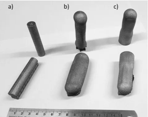
Following HIPing, visual examination of the samples with encapsulated sintered powder revealed that there had been a signiicant decrease in volume, whereas no change was apparent in the EBM consolidated samples that were HIPed following manufacture. In addition, the solid skin had buckled in some locations as exempliied in Fig. 2b,c.
Microstructural observations in graded material.
he “beetle” sample was used to examine both EBM-H and EBS-H material, and the structure of the graded materials. he microstructure of standard EBM TI-6Al-4V was not examined in detail due to the number of already existing studies (e.g. refs.5,6,17).Grain morphology. Backscatter SEM images of the beetle section revealed diferences in microstructure (Fig. 3), between regions. here was no visible void of boundary between the two regions implying good bonding between the two. he EBM-H material consisted of α laths transformed from prior β grains with both Widmanstätten and colony morphologies present, and ine residual β remaining between laths. In contrast, the EBS-H regions were primarily composed of α with a morphology much closer to equiaxed and coarser β primarily at α grain boundary triple points.
An EBSD map of the entire beetle is shown in Fig. 4a, providing information about the orientations of grains. Visual inspection of the data is suicient to identify the beetle shape, albeit slightly distorted. In addition, the melted skin of the capsule is also visible in the upper corners of the map. he number density of grain bounda-ries is higher in the EBS-H region in comparison to the EBM-H. Indeed, it appears that the EBM-H areas have colonies of multiple similar orientated laths, which appear as a single grain due to the resolution of the EBSD not being able to detect the thin β between the laths.
[image:5.595.156.396.46.236.2] [image:5.595.159.520.296.417.2]he boundary between the EBM-H and EBS-H regions becomes much more visually apparent when sotware is used to calculate the high temperature β grain structure from which the α phase transformed (Fig. 4b). his is primarily due to the extent with which the reconstruction sotware was able to calculate the β phase grain ori-entations. In the EBM-H regions, large β grains can be observed. In contrast, in much of the EBS-H region the Figure 2. Photograph of samples following HIPing, with alphabetical designations corresponding respectively to (a) EBM-H, (b) EBS-H, and (c) EBS/EBM-H.
sotware was unable to determine the β phase orientations resulting in larger ratio of unidentiied (black) points. he β grains that the sotware was able to identify within the EBS-H region have a much smaller average size than those in the EBM-H region. However, the number of non-indexed points, and there being too few points in each grain, means that reliable grain size statistics could not be produced.
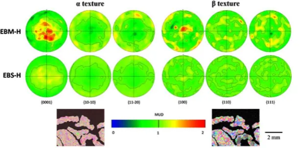
Texture. It is immediately apparent from inspection of the pole igures (Fig. 5) generated from the α phase EBSD maps (inset) that the crystallographic texture of the two regions also showed some considerable diferences. he EBM-H regions melted by the electron beam had a maximum-recorded multiple of uniform density (MUD) of 2.1, whereas the EBS-H regions showed a maximum of 1.3. It is clear that the EBS-H region was less textured than the EBM-H region, however, there was still some observable departure from a completely random structure.
A similar trend was observed when the initial solidiication β grain structure was reconstructed, and used to plot pole igures (Fig. 5). In particular, a MUD of 1.8 was recorded in the EBM-H region in comparison to 1.3 in the EBS-H region.
Density measurements and defect morphology.
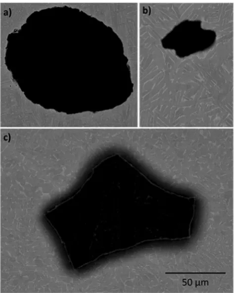
All of the samples were found to contain porosity. However, there were diferences in the pore volume fractions measured, with the highest in the standard EBM material (0.069%), followed by the EBS-H (0.020%), and the lowest in EBM-H (0.005%). [image:6.595.157.395.45.221.2]One of the largest pores found in each condition is shown in Fig. 6. EBM material contained mainly round pores, with fewer more irregular voids also observed. he pores observed in the EBM-H material were smaller and less regular. It is notable that of the planes observed, the largest pore was found in EBS-H. his pore (Fig. 6c) was also irregular in morphology, although many of the other pores in this material were close to circular. Figure 4. Grain orientation data regarding the beetle capsule. (a) Room temperature α phase grain orientation information collected by EBSD from the beetle sample; (b) Initially solidiied β microstructure reconstructed from, and at the same scale as, data in (a). Here, the build direction (z) is normal to the plane of the page.
[image:6.595.156.463.296.448.2]Mechanical properties.
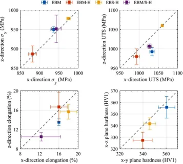
Hardness. he hardness map presented in Fig. 7 corresponds to material previ-ously shown in the EBSD map in Fig. 4. It clearly demonstrates the variation in measured hardness between the EBM-H and EBS-H consolidated regions in polishing plane of the beetle sample. Similar to the EBSD map, the beetle shape melted during EBM is clearly visible, although distorted in the same way as the EBSD data. he soter melted skin of the capsule is also visible in the upper corners of the map. Areas melted during EBM processing tended to be soter than those densiied during HIPing, with approximately 10% diference in recorded hardness.he average and standard deviation recorded ater 25 hardness tests in the polished planes of the tensile blanks used for density determination is shown in Fig. 8. All samples were found to be slightly harder in the x-y plane than the x-z plane, with EBM showing the highest hardness, and EBM-H the lowest.
Static tensile testing. In order to enable numerous results of diferent material conditions and testing directions to be quickly compared, the yield stress (σ
y), ultimate tensile stress (UTS) and elongation to failure have been
[image:7.595.158.395.46.343.2]plotted in Fig. 8, while example stress strain plots for each condition are shown in Fig. 9. EBS-H material was Figure 6. SEM images of examples of larger porosity found in (a) EBM, (b) EBM-H, and (c) EBS-H. All images to same scale.
[image:7.595.156.396.402.557.2]found to have a higher σy and UTS than standard EBM, and EBM-H material lowest. When the interface between
[image:8.595.158.516.49.368.2]EBM-H and EBS-H (EBM/S-H) was tested, the results were found to be reduced below the EBS-H material, but similar to standard EBM. he scatter was also lower in the EBS-H in comparison to all other conditions, for both sigma-y and UTS. In fact, when the data was rounded in accordance with ASTM E29, all the tested EBS-H sam-ples (6 total, 3 in × and 3 in z) were reported to have a UTS of 1060 MPa. he EBS-H is both highly consistent and isotropic. In contrast, EBM and EBM/S-H were found to have higher UTS in the x-direction than the z. he elongation to failures recorded displayed more scatter, but in general, the EBM-H and EBS-H showed the highest values, followed by the standard EBM and then the EBM/S-H.
Figure 8. Comparison of data collected in this study showing mechanical property anisotropy. he mean value recorded in the x-direction is plotted against the mean value in the z-direction. he error bars indicate the standard deviation of 3 tensile tests in each condition and direction, for σy, UTS and elongation, and 25 hardness
tests. he dotted line indicates equivalence between testing directions, i.e. perfectly isotropic behaviour.
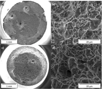
[image:8.595.157.394.450.599.2]Examples of EBM and EBS-H fracture surfaces are shown in Fig. 10. Defects are observable on all fracture surfaces, although a greater number are visible in the EBM material. Higher resolution images of the fracture surfaces revealed similar morphologies for all conditions and testing directions.
Discussion
It has been demonstrated that it is possible to produce high density Ti-6Al-4V parts with graded microstructure and properties by combining the EBM and HIP process. It is clear is that the 2 mm outer skin of the capsules melted by the electron beam during the EBM process was impervious to the argon used during the HIPing pro-cess. he capsules thus acted in a manner analogous to a standard HIP can. hat is, the capsules collapsed and provided the pressure on the powder to consolidate to a dense volume at the temperatures experience during HIPing. Furthermore, like a HIP can, the skin was removed by machining in order to reveal and assess the con-solidated EBS-H material within.
Densi cation of powder
From the results shown above it is apparent that the standard HIP cycle applied was suicient to almost completely densify the sintered powder. Titanium powder sintered during the EBM pro-cess typically has a density of around 50–60%14. In contrast, examination of the EBS-H material revealed a densityof >99.9%. During the HIP cycle, the powder particles will have been brought into contact and difusion bonded, as per a standard powder HIP process. he thermophysical efects during HIPing have been well described by previous studies26–28.
It would be possible to manufacture whole components with this technique, or alternatively selectively melt regions to generate a graded microstructure (see below). Powder metallurgy HIP is well established method to create near net shape components with ine homogeneous microstructures27. Typically, this is achieved by
weld-ing HIP cans to create a preform skin, which is then illed with powder and HIPed. Finally, the skin is machined of to reveal the component beneath. By generating the skin using EBM, the labour costs will be signiicantly reduced. Furthermore, the build time of the EBM process will be reduced due to the lesser melt volume, reduc-ing costs in comparison to standard EBM. Of course, unlike in standard EBM AM, it is essential that the part is HIPed for it to have any load bearing strength. However, given the strong dependence of the fatigue life on the presence of porosity/defects, any components that would experience cyclic load in service would likely be HIPed to improve their fatigue life. hus, the HIP process may be adopted as standard procedure for AM components, and hence its use to consolidate the powder would not result in any additional cost.
[image:9.595.157.516.44.356.2]the argon within powder would remain and could potentially regrow if the HIPed part was heat treated at a high enough temperature. Indeed, such efects have been observed by other authors when heat treating standard pow-der HIP Ti-6Al-4V32. he efect of this on the mechanical property requires scrutiny.
While the EBM process does not happen in a high vacuum, but at controlled vacuum of 2 × 10⁻³ mbar, the
relatively low helium pressure would lead to very limited gas entrapment in comparison to SLM. In contrast to argon illed SLM pores, these helium pores would contain a much lower number of moles of atoms, due to the signiicantly reduced pressure when they were irst entrapped. As such, upon HIPing the volume of gas could become much smaller before reaching equilibrium with HIPing pressure. hey would thus be unlikely to regrow to the same extent as the argon illed pores introduced at atmospheric pressure during SLM.
Microstructure and mechanical properties.
While EBM of Ti-6Al-4V is a relatively well-established AM technique, we have shown the static mechanical properties can be improved by harnessing the EBS-H method-ology proposed here. he EBS-H Ti-6Al-4V was found to have higher yield, UTS and elongation than standard EBM Ti-6Al-4V, exemplifying the beneits of this modiied manufacturing route. In addition, the reduced scatter in results may allow smaller safety factors to be used and give engineers the ability to maximise the eiciency of the material. While it appears that the mean values of EBS-H are closer to isotropic than standard EBM, the scatter in both datasets makes it hard to draw deinitive conclusions. In particular, for all conditions the diference from iso-tropic behaviour is not statistically signiicant, as has been found by a number of other studies of EBM material33.he grains within the EBS-H material appear to have a size greater than the width of the lathes in the EBM-H material (Fig. 3), which would suggest according to a simple application of the Hall-Petch relationship that the material would have a lower yield stress. However, as exempliied in the EBSD data, the colonies are signiicantly larger in the EBM-H than the grains in EBS-H. he colonies can allow slip through multiple laths and thus colony size can be correlated with mechanical performance34. Hence, the larger colonies lead to the lower yield stress
recorded for the EBM and EBM-H compared to EBS-H.
he α grains in the EBS-H material appears more equiaxed than those in the EBM or EBM-H, which appear as ine and slightly coarser laths respectively17. his can be attributed to the difering routes by which the
microstruc-ture develops. he development of the typical EBM Ti-6Al-4V microstrucmicrostruc-ture has been described by a number of authors5,6,17. In brief, the rapid cooling of initially solidiied coarse columnar β grains through the β transus leads to
a ine Widmanstätten microstructure. Subsequent HIPing of EBM leads to a coarsening of the microstructure due to growth at the high temperatures experienced during HIP17. In contrast, when titanium powder particles are
com-pacted and densiied during HIP the material remains below the β-transus and consolidation occurs by difusion. Contrary to the results presented here, previous studies of Ti-6Al-4V consolidated from powder HIP have observed a higher aspect ratio, lath morphology of the grains28,35. Subsequent heat treatments were found to an
increase the measured fraction of equiaxed grains, proportional to treatment time and temperature35. he mostly
equiaxed α grains observed in the HIP consolidated powder analysed in this paper (EBS-H) is thus more typical of heat-treated HIP consolidated powder. While there was no heat treatment following the HIP for the EBS-H material it is important to note that the powder was held at high temperature during the initial EBM sample manufacture for a signiicant period of time. In addition, this powder had been recycled a number of times so it is diicult to ascertain exactly how long the powder had been held at high temperature other than to say it is likely that much of it had experienced tens of hours above 700 C. At this high temperature α grains within the powder may have begun to spheridise during the EBM build, prior to the HIP. his spheroidisation may remain following EB sintering and HIP and could thus account for the larger fraction of equiaxed α that was observed in EBS-H than has been found by previous authors.
A note of caution must be made about the potential fatigue properties of the EBS-H Ti-6Al-4V, and the poten-tially detrimental pores that did remain in the EBS-H material. In particular, the large irregular pore shown in Fig. 6c, which has a morphology suggesting it originated at the interface between powder particles. Unfortunately, such large irregular defects would likely have a signiicant efect on the fatigue life due to the stress concentra-tion they generate12,36. However, there is scope to modify the HIP cycle to try to avoid such defects appearing28.
In addition, the sintering step during EBM could be modiied to create a more dense sintered volume prior to HIPing which may aid attempt to reduce porosity in EBS-H material.
he tensile testing conducted here suggests there is no reduction in yield/UTS associated with the interface between EBM/S-H in comparison to pure EBM-H. hus, designers can generate CAD models employing materi-als with site-speciic properties, where the local material characteristics are optimised for the local conditions, but with no reduction in strength associated with the overlap. However, the reduction in ductility may be of concern. It is notable that should this technique be applied to other alloys, it may be possible to generate an even greater change in properties. he titanium alloy used in this study was chosen due to the availability of literature, feed-stock materials, and process parameters for both AM and HIP cycles. However, the initially solidiied β rapidly transforms to ine α laths as the material cools below the β transus. hus, the potential inluence of the columnar grains on mechanical properties is reduced. In contrast, in other engineering alloys the columnar grains could be retained, allowing the possibility of a greater duality in the microstructure and properties. For examples, colum-nar regions could be used to increase the resistance in creep in selected regions, while more equiaxed areas could provide a higher yield stress in others.
Conclusions
A technique has been demonstrated to generate material with better static mechanical properties than standard EBM Ti-6Al-4V. his was achieved by using EBM AM to generate a hollow preform illed with sintered powder, before HIPing to full density. he improvement in properties was attributed to a more equiaxed microstructure, which has a smaller grain size than the efective grain (colony) size of EBM Ti-6Al-4V. Importantly, by selectively melting some of the internal section of the samples, a graded microstructure can be generated. A complex graded microstructure was manufactured and changes in grain morphology and orientation were found to closely align with the intended geometry. A reduced but not eliminated texture was observed in the HIP consolidated powder in comparison to melted powder, and mechanical tests revealed behaviour that was closer to isotropic. However, the limited data available requires further testing to collaborate our results.
References
1. Gibson, I., Rosen, D. W. & Stucker, B. Additive Manufacturing Technologies, 1st ed., Springer, London (2010).
2. Frazier, W. E. Metal additive manufacturing: A review. J. Mater. Eng. Perform.23, 1917–1928, https://doi.org/10.1007/s11665-014-0958-z (2014).
3. Smith, C. J., Tammas-Williams, S., Mahoney, P. S. & Todd, I. 3D printing a jet engine: An undergraduate project to exploit additive manufacturing now and in the future, Mater. Today Commun. 16. https://doi.org/10.1016/j.mtcomm.2018.03.006 (2018). 4. Edwards, P., O’Conner, A. & Ramulu, M. Electron Beam Additive Manufacturing of Titanium Components: Properties and
Performance. J. Manuf. Sci. Eng.135, 061016, https://doi.org/10.1115/1.4025773 (2013).
5. Antonysamy, A. A., Meyer, J. & Prangnell, P. B. Efect of build geometry on the??-grain structure and texture in additive manufacture of Ti6Al4V by selective electron beam melting. Mater. Charact.84, 153–168 (2013).
6. Hernández-Nava, E. et al. he efect of defects on the mechanical response of Ti-6Al-4V cubic lattice structures fabricated by electron beam melting. Acta Mater.108, 279–292 (2016).
7. Edwards, P. & Ramulu, M. Fatigue performance evaluation of selective laser melted Ti-6Al-4V. Mater. Sci. Eng. A.598, 327–337, https://doi.org/10.1016/j.msea.2014.01.041 (2014).
8. Gong, H., Rai, K., Gu, H., Starr, T. & Stucker, B. Analysis of defect generation in Ti-6Al-4V parts made using powder bed fusion additive manufacturing processes. Addit. Manuf.1, 87–98, https://doi.org/10.1016/j.addma.2014.08.002 (2014).
9. Liu, Y. J. et al. Microstructure, defects and mechanical behavior of beta-type titanium porous structures manufactured by electron beam melting and selective laser melting. Acta Mater.113, 56–67, https://doi.org/10.1016/j.actamat.2016.04.029 (2016).
10. Liu, Y. J. et al. Compressive and fatigue behavior of beta-type titanium porous structures fabricated by electron beam melting. Acta Mater.126, 58–66, https://doi.org/10.1016/j.actamat.2016.12.052 (2017).
11. Tammas-Williams, S. et al. XCT analysis of the influence of melt strategies on defect population in Ti-6Al-4V components manufactured by Selective Electron Beam Melting. Mater. Charact.102, 47–61, https://doi.org/10.1016/j.matchar.2015.02.008 (2015).
12. Tammas-Williams, S., Withers, P. J., Todd, I. & Prangnell, P. B. he Inluence of Porosity on Fatigue Crack Initiation in Additively Manufactured Titanium Components, Sci. Rep. 7. https://doi.org/10.1038/s41598-017-06504-5 (2017).
13. Harrison, N. J., Todd, I. & Mumtaz, K. Reduction of micro-cracking in nickel superalloys processed by Selective Laser Melting: A fundamental alloy design approach. Acta Mater.94, 59–68, https://doi.org/10.1016/j.actamat.2015.04.035 (2015).
14. Smith, C. J., Tammas-Williams, S., Hernandez-Nava, E. & Todd, I. Tailoring the thermal conductivity of the powder bed in Electron Beam Melting (EBM) Additive Manufacturing, Sci. Rep. 7 https://doi.org/10.1038/s41598-017-11243-8 (2017).
15. Tian, Y. et al. Material interactions in laser polishing powder bed additive manufactured Ti6Al4V components. Addit. Manuf.20, 11–22, https://doi.org/10.1016/j.addma.2017.12.010 (2018).
16. Tammas-Williams, S., Withers, P. J., Todd, I. & Prangnell, P. B. he Efectiveness of Hot Isostatic Pressing for Closing Porosity in Titanium Parts Manufactured by Selective Electron Beam Melting, Metall. Mater. Trans. A Phys. Metall. Mater. Sci.47, 1939–1946, https://doi.org/10.1007/s11661-016-3429-3 (2016).
17. Al-Bermani, S. S., Blackmore, M. L., Zhang, W. & Todd, I. he origin of microstructural diversity, texture, and mechanical properties in electron beam melted Ti-6Al-4V, Metall. Mater. Trans. A Phys. Metall. Mater. Sci.41, 3422–3434 (2010).
18. Das, S., Wohlert, M., Beaman, J. J. & Bourell, D. L. Producing Metal Parts with Selective Laser Sintering/Hot Isostatic Pressing Pressing. JOM.50, 17–20 (1998).
19. Cai, C. et al. A novel hybrid selective laser melting/hot isostatic pressing of near-net shaped Ti-6Al-4V alloy using an in-situ tooling: Interfacial microstructure evolution and enhanced mechanical properties. Mater. Sci. Eng. A.717, 95–104, https://doi.org/10.1016/j. msea.2018.01.079 (2018).
20. Hassanin, H. et al. Net-shape manufacturing using hybrid selective laser melting/hot isostatic pressing, Rapid Prototyp. J.23, 720–726, https://doi.org/10.1108/RPJ-02-2016-0019 (2017).
21. Tammas-Williams, S. & Todd, I. Design for additive manufacturing with site-speciic properties in metals and alloys. Scr. Mater.135, 105–110, https://doi.org/10.1016/j.scriptamat.2016.10.030 (2017).
22. Zhao, S. et al. Compressive and fatigue behavior of functionally graded Ti-6Al-4V meshes fabricated by electron beam melting. Acta Mater.150, 1–15, https://doi.org/10.1016/j.actamat.2018.02.060 (2018).
23. Smith, C. J. et al. Dimensional accuracy of Electron Beam Melting (EBM) additive manufacture with regard to weight optimized truss structures, J. Mater. Process. Technol. 229. https://doi.org/10.1016/j.jmatprotec.2015.08.028 (2016).
alloy based on heat response. Mater. Sci. Eng. A.639, 327–334, https://doi.org/10.1016/j.msea.2015.05.041 (2015).
33. Antonysamy, A. A. Microstructure, Texture and Mechanical Property Evolution during Additive Manufacture of Ti6Al4V alloy using Laser, Electron Beam, and Arc Melting Techniques for Aerospace Applications, PhD hesis, University of Manchester (2012). 34. Lütjering, G., Williams, J. C. Titanium, 2nd ed., Springer 2007.
35. Qu, S. G., Sun, F. J., Yuan, Z. M., Li, G. & Li, X. Q. Efect of annealing treatment on microstructure and mechanical properties of hot isostatic pressing compacts fabricated using Ti–6Al–4V powder. Powder Metall.58, 312–319, https://doi.org/10.1179/174329011 5Y.0000000014 (2015).
36. Murakami, Y. Material defects as the basis of fatigue design. Int. J. Fatigue.41, 2–10, https://doi.org/10.1016/j.ijfatigue.2011.12.001 (2012).
Acknowledgements
his research was funded in part by the EPSRC programs Designing Alloys for Resource Eiciency (DARE) (EP/ L025213/1) and Manufacture using Advanced Powder Processes (MAPP) (EP/P006566/1), and the ATI Horizon program.
Author Contributions
E.H.-N., P.M., C.J. and S.T.-W. devised and performed the experimental methodology throughout this paper. EBSD microscopy was performed by J.D., micro-hardness maps by P.M. and SEM by E.H.-N. he manuscript was written by E.H.-N., P.M., C.J.S. and S.T.-W. with contributions from I.T. All authors reviewed the manuscript.
Additional Information
Competing Interests: he authors declare no competing interests.
Publisher’s note: Springer Nature remains neutral with regard to jurisdictional claims in published maps and institutional ailiations.
Open Access This article is licensed under a Creative Commons Attribution 4.0 International License, which permits use, sharing, adaptation, distribution and reproduction in any medium or format, as long as you give appropriate credit to the original author(s) and the source, provide a link to the Cre-ative Commons license, and indicate if changes were made. he images or other third party material in this article are included in the article’s Creative Commons license, unless indicated otherwise in a credit line to the material. If material is not included in the article’s Creative Commons license and your intended use is not per-mitted by statutory regulation or exceeds the perper-mitted use, you will need to obtain permission directly from the copyright holder. To view a copy of this license, visit http://creativecommons.org/licenses/by/4.0/.