This is a repository copy of Comment on 'The cutting of metals by plastic buckling' by Udupa et al..
White Rose Research Online URL for this paper: http://eprints.whiterose.ac.uk/132979/
Version: Accepted Version
Article:
Childs, THC (2018) Comment on 'The cutting of metals by plastic buckling' by Udupa et al. Proceedings of the Royal Society A: Mathematical, Physical and Engineering Sciences, 474 (2216). ISSN 1364-5021
https://doi.org/10.1098/rspa.2018.0170
(c) 2018 The Author(s) Published by the Royal Society. All rights reserved. This is an author produced version of a paper accepted for publication in Proceedings of the Royal Society A. Uploaded in accordance with the publisher's self-archiving policy.
[email protected] https://eprints.whiterose.ac.uk/
Reuse
Items deposited in White Rose Research Online are protected by copyright, with all rights reserved unless indicated otherwise. They may be downloaded and/or printed for private study, or other acts as permitted by national copyright laws. The publisher or other rights holders may allow further reproduction and re-use of the full text version. This is indicated by the licence information on the White Rose Research Online record for the item.
Takedown
If you consider content in White Rose Research Online to be in breach of UK law, please notify us by
1 Comment on ‘The cutting of metals by plastic buckling’ by Udupa et al.
Author: T.H.C. Childs*
*School of Mechanical Engineering, University of Leeds, Leeds LS2 9JT, UK
e-mail: [email protected]
Abstract.
In a recent paper on machining annealed copper at a low cutting speed, and at an uncut chip
thickness one tenth of the mean grain size of the copper, Udupa et al. (Proc. R. Soc
A473:20160863, doi:10.1098/rspa.2016.0863) report chip thicknesses larger than 10 times the
uncut thickness and then a new mode of chip formation. Plastic bulging occurs in the surface
of the copper ahead of the tool, leading to chip formation by a series of folds. The strain in
the chip is less than that expected in a chip formed by shear according to long-standing
classical theory. The authors suggest that the foundations of that theory need to be
re-examined. In response, continuum mechanics numerical simulations presented here show a
continuous transition from the classical condition towards that observed by Udupa et al. as
the ratio of chip thickness to uncut thickness increases above ≈ 7. Bulging is obtained by
introducing (approximately) material heterogeneity to the simulations at a grain size scale but
whether such heterogeneity is essential for the bulging flows remains an open question.
Key words. Cutting, plasticity, annealed metals, instability, chip formation, finite element
2 1. Background
Udupa et al. [1] report observations of a bulging instability in the surface of work material
ahead of the chip formation zone in metal cutting. It results in chip formation by a folding
flow instead of by the steady shearing that is the basis of long-standing theory. They develop
an approximate bifurcation analysis to predict the bulging as a form of buckling and suggest
that the foundations of the long-standing theory need to be revisited. This can be taken in two
ways: exploring the limits of the long-standing theory, or revisiting models of surface
instability. The comments here respond mainly to the first and in a limited way to the second.
The main results in [1] are for machining an annealed copper, of mean grain size 0.5
mm with a tool of rake angle = 0° and edge radius less than 5 m, at a cutting speed vc = 0.5
mm/s and uncut chip thickness h = 0.05 mm. Subsidiary results are for the same conditions
except = 45°, and for machining the copper with the = 0° tool after applying a pre-strain
p
≈ 2.5. The comments here are made around these conditions. They are based on results
from finite element simulations carried out in response to the discussion in [1], though with a
tool of edge radius 10 m (for minimum mesh size reasons), using the bespoke for machining
commercial finite element software AdvantEdge-2D, developed from [2], with its option that
enables users to include their own material flow stress model. Details are in Appendix A.
2. The limits of long-standing theory.
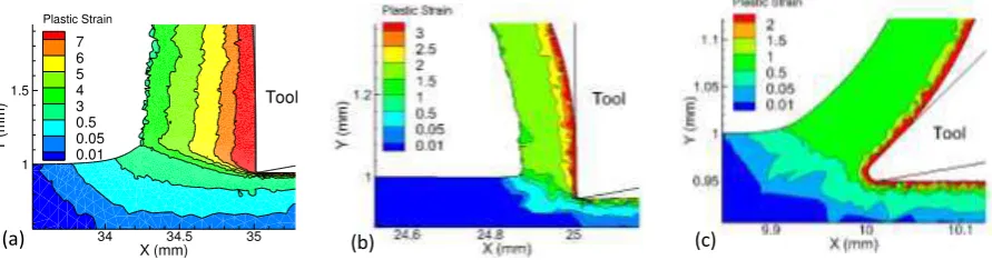
Simulated chip formations and strain distributions for the conditions in [1] are in figure 1.
The much reduced chip thickness caused by pre-straining the work (figure 1b compared to
1a) and the much smoother free surface when = 45° (figure 1c) follow the observations in
[1]. The chip thickness in figure 1a is ≈ 14 times the uncut thickness. Bulging and folding
flow is not observed but the extent of plastic strain ahead of the chip and the strain gradient
[image:3.595.77.523.597.714.2]across the chip are significantly larger than in figures 1b and c.
Figure 1. Predicted chip formations, with strain contours: (a) p= 0, = 0°, (b) p= 2.5, = 0°, (c) p= 0, = 45°.
X (mm)
Y
(m
m
)
34 34.5 35
1 1.5
Plastic Strain
7 6 5 4 3 0.5 0.05 0.01
Tool
3 Long standing theory in its most basic form, rigorously applicable only to non-strain
hardening metals and straight chips, considers a chip of thickness t to be formed from the
uncut thickness h by shear across a flat plane inclined at the shear plane angle to vc. It is a
standard result that , t/h and are linked geometrically (equation 1), and that the equivalent
strain in the chip due to the shear,shea r, depends on and (equation 2).
cos sin
tan t h (1)
1 3 cos sin cos
shear
(2)
Real chip formations are more complicated but t/h can still be measured and an
equivalent and shea r calculated. The actual mean strain simula tion in a simulated chip can be
found by averaging across the chip thickness. This includes the secondary shear strain next to
the tool, not accounted for in equation 2. Thus simula tion/shea r > 1.0 is expected for a chip
formed in simple shear. In fact, for the case of figure 1a the ratio simula tion/shea r is 0.64, less
than 1 and also similar to that in [1].
Simulations, with = 0° and p from 0 to 3, and with p = 0 and from 0° to 45°
show that simula tion/shea r reduces below 1.0 by > 10% for t/h greater than ≈ 7 (figure 2a). The
example of figure 2b (p = 0, = 0°) demonstrates that the reduction is due to compression
ahead of the shear zone. Material approaching the shear zone is compressed two- to
three-fold before shearing. From the strain rate contours the highest strain rates in the shear zone
occur along a plane inclined to vcat ≈ 1.5 times the angle from t/h (equation 1). The final
strain is then the sum of a compression ≈ ln2.5 and a shear ≈ 2/3rd
of that from equation 2.
Figure 2. (a) the dependence of simula tion/shea r on t/h; (b) pre-shear compression, example of
p
= 0, = 0°, to explain simula tion/shea r < 0.9 for t/h > 7. (simula tion/shea r > 1.1 for t/h < 2 is due to including the large secondary shear strains next to the rake face (figure 1) in simula tion.)
0 5 10 15 20
0.00 0.25 0.50 0.75 1.00 1.25
0.9
= 0o, 0 < p < 3.0
0 <o < 45,
p = 0
simulation
/
shear
t / h
4 The separation in figure 2b between the actual maximum strain rate plane and that
from equation 1 is another aspect of the departure of chip formation from simple shear. For
t/h less than ≈ 7 there is no separation (as is classically observed and as is the basis of many
successful analyses of chip formation [3]). Beyond that, with increasing t/h, pre-compression
increasingly modifies chip formation, towards the extreme form observed in [1].
3. Surface instabilities.
Figure 3a shows the chip formation when p= 0, = 0°, at greater magnification than in
figure 1a. Strain contours are cut-off above 4 to concentrate on the pre-shear and chip surface
regions. The pre-shear free surface deforms steadily, concave upwards with no bulging.
Surface instability occurs at the exit to the shear region. In this case bulging ahead of the
shear region requires heterogeneity to be introduced. The software is able to simulate this in a
limited way, by modelling the work piece as two slabs separated by a slice of some other
material. Figure 3b shows chip formation when a softer slice has just entered the pre-shear
region. It is 0.5 mm wide to match the grain size in [1], is initially parallel-sided and its flow
stress is 80% of that to either side (see Appendix A). The free surface ahead of the chip is
now convex upward with an incipient bulge, with shear split into major and minor bands.1
Figure 3. (a) strain contours (b) strain rate contours, with (a) no surface bulge in the pre-shear zone, and (b) an incipient bulge forming as a softer slice enters the pre-shear zone.
The strain rate field in figure 3b is similar to that in wedge compression under traction
[4]. The bulge would develop by squeezing between the two shear regions and folding would
follow from transfer of shear severity between the bands as the work steadily approaches the
1The software’s limitation is that the slab/slice interfaces do not transmit shear, only compressive normal
stresses. It is not possible realistically to follow the growth of the bulge as the slice moves towards the major shear band. But at the early stage of figure 3b shear stresses are naturally low across the interfaces, as judged by the near-continuity of the strain rate contours. The limitation is then not so distorting of the flow.
[image:5.595.103.481.456.602.2]5 tool. It gives a deterministic explanation of bulging, alternative to buckling, that is not
considered in [1] despite split and oscillating shear zones having been previously reported in
machining brass, albeit on a finer scale, in figure 12 of [5] and the ghost of a similar field
having been reported for sinuous flow in figure 2 of [6]. Publication of the strain rate fields
from the streak lines in [1] would be valuable. Further, although heterogeneity is responsible
for bulging in figure 3b, it is possible to imagine the same mechanism occurring in more
severe (larger t/h) conditions without the need for that. In contrast, prior work with a softer
slice in the manner of figure 3b shows that heterogeneity is necessary in the less severe
condition of plastic wave flow under a sliding wedge [7]. The role of heterogeneity merits
further study.
4. Final comments.
This comment’s simulations show a continuously changing mode of chip formation as t/h increases from ≈ 7 to 14: shear gives way to pre-compression and shear but the bulging and folding state seen in [1] is not reached. Bulging, with more the appearance of wedge
compression under traction than buckling, occurs at large t/h when local softening is
introduced, to represent the effect of grain-scale heterogeneity but in this condition, due to a
software limitation, it has not been possible to continue the simulations to what might
become a folding flow. In this comment’s view whether [1]’s bulging has a bifurcation or a
more deterministic explanation, and whether heterogeneity is essential for its occurrence
remain open questions.
Competing interests. The author has no competing interests.
Acknowledgement. The author is grateful to Professor S. Chandrasekar (co-author of [1]) for
making available additional information and for constructive discussions during preparation
of these comments.
Funding. These comments are unfunded.
Appendix A. The model details
A Johnson-Cook flow stress model is applied, omitting temperature and strain rate terms, as
in [1] because of the low cutting speed condition that is being modelled, but with two
modifications from its usually presented form (equation A1): pre-strain is accommodated by
6 ceases. With this temperature and time independent flow stress model simulation results are
independent of cutting speed. vc = 100 m/min is chosen as the elapsed computing time is
hugely reduced compared to that for vc = 0.5 mm/s.
,
, n
p p c
n
c p c
A B
A B
(A1)
The software’s plane strain sliding friction model is applied (equation A2), with f the
friction stress and n the normal stress between chip and tool and the friction coefficient.
min( 3 , )
f n
(A2)
Selecting A = 90 MPa, B = 290 MPa and n = 0.31, as referenced in [1], with c in the
range 3 to 3.5 and from 0.3 to 0.35, gives predicted chip thickness to uncut chip thickness
ratios and forces similar to those in [1]. c = 3.4 and = 0.33 are chosen for the results in
Sections 2 and 3. A = 72 MPa and B = 235 MPa are chosen for the softer slice in figure 3b.
References
1. Udupa A, Viswanathan K, Ho Y, Chandrasekar S. 2017 The cutting of metals via plastic
buckling. Proc. R. Soc. A473, 20160863. (doi:10.1098/rspa.2016.08630)
2. Marusich T, Ortiz M. 1995 Modelling and simulation of high speed machining. Int. J.
Numer. Methods Eng. 38, 3675-3694. (doi:10.1002/nme.1620382108)
3. Oxley PLB. 1989 Mechanics of machining. Chichester, UK: Ellis Horwood Ltd., Chs. 5-7.
4. Johnson KL. 1968 Deformation of a plastic wedge by a rigid die under the action of a
tangential force. J. Mech. Phys. Solids 16, 395-402. (doi:10.1016/0022-5096(68)90003-3)
5. Guo Y, Compton WD, Chandrasekar S. 2015 In situ analysis of flow dynamics and
deformation fields in cutting and sliding of metals. Proc. R. Soc. A471, 20150194.
(doi:10.1098/rspa.2015.0194)
6. Yeung H, Koushik V, Compton WD, Chandrasekar S. 2015 Sinuous flow in metals. Proc.
Natl. Acad. Sci. USA 112, 9828-9832. (doi:10.1073/pnas.1509165112)
7. Vandana AS, Sundaram K. 2017 Interaction of a sliding wedge with a metallic substrate