This is a repository copy of
Medium Access Control Protocol for Wireless Sensor
Networks in Harsh Environments with Directional Antennas
.
White Rose Research Online URL for this paper:
http://eprints.whiterose.ac.uk/135277/
Version: Accepted Version
Proceedings Paper:
Chau, A, Dawson, J F orcid.org/0000-0003-4537-9977, Mitchell, P D
orcid.org/0000-0003-0714-2581 et al. (1 more author) (2018) Medium Access Control
Protocol for Wireless Sensor Networks in Harsh Environments with Directional Antennas.
In: Loughborough Antennas Propagation Conference (LAPC 2018). , Loughborough, UK .
https://doi.org/10.1049/cp.2018.1471
[email protected] https://eprints.whiterose.ac.uk/ Reuse
["licenses_typename_other" not defined]
Takedown
If you consider content in White Rose Research Online to be in breach of UK law, please notify us by
Medium Access Control Protocol for Wireless Sensor Networks in
Harsh Environments with Directional Antennas
A Chau*, J F Dawson*, P D Mitchell*, and T H Loh
†*University of York, UK, arnold.chau, john.dawson, [email protected], † National Physical Laboratory, UK, [email protected]
Keywords: ALOHA, Medium Access Control, Wireless Sensor Network, Directional Antenna.
Abstract
In this paper, we consider the application of directional antennas to the hub node of a wireless sensor network (WSN), whilst retaining an omni-directional antenna on each sensor node, thus enhancing link performance without increasing the cost, complexity or energy consumption of the sensor nodes. We propose a simple medium access control (MAC) protocol for the hub node, based on the ALOHA protocol but designed to support multiple antennas on the hub, whilst the sensors retain the original ALOHA protocol. The analysis and simulation results show a 217% increase in throughput. Further possibilities of this architecture include increased range and/or the reduced sensor power consumption.
1 Introduction
A number of previous authors have considered the use of multi-input-multi-output (MIMO), or directional antennas to improve the performance of wireless protocols. Hunchangsith et al [1] provided a mathematical evaluation of the performance of a MIMO ALOHA protocol while employing multiple antennas at the hub, where nodes are considered free to access the medium at random. The nodes within the network will compete to access the medium without coordination [2]. This work shows that as the number of antennas at the hub increases, the throughput will also increase. However, similar to many papers [1, 3-7], the antenna models are idealised. On the other hand, Ward et al [8] presented a protocol using a directional antenna and based on the slotted ALOHA protocol, where time is divided into slots and all nodes are synchronised. Sensor nodes will only start to transmit messages at the beginning of the slots. If two or more nodes try to transmit at the same time, a collision will be detected by all nodes before the end of the slot. However, in this proposed protocol, the receiving base station has to be equipped with both omni-directional and a set of omni-directional antennas by means of adaptive array antennas.
Although an ALOHA protocol with an additional time division multiple access (TDMA) frame has been presented by Chang in [3] to investigate the performance of a multi-beam random access network for simultaneous communications, it was assumed, in their analysis, that the physical space was perfectly divided by the number of antennas without any overlap. The
previous work of Nasipuri [4] and Choudhury et al [5] showed that the link performance of communication systems using carrier sensing multiple access (CSMA) protocols can be improved by the use of directional antennas, due to the possibility of spatial reuse. However, both studies assumed that there was no overlap between the antenna beams in their simulation. Fahmy and Todd [6] have shown some performance improvement in a CSMA protocol with directional antenna using an adaptive antenna array on all sensor nodes. In this paper, we propose a simple medium access control (MAC) protocol method for the hub node based on the ALOHA protocol with multiple antennas. This proposed method has the advantage over CSMA protocols that it does not require the sensor nodes to perform carrier sensing and does not require all nodes to be equipped with directional antennas. Atmaca and Erturk [7] evaluated the link capacity improvements of spatial division multiple access (SDMA) and TDMA protocols by using directional antennas. However in this protocol, it was assumed that the hub knows the location of all the sensor nodes in the network, and all nodes are synchronised so that they know when they can transmit. It was also assumed that all packets with lower signal-to-noise (SNR) compared to the desired packet will be eliminated. They remove all packets with SNR below a certain quality threshold at the antenna without sending it to the MAC layer in order to maintain better link performance. Mudliar and Pillutla evaluated a memory guided MAC protocol based on CSMA protocol in [9], using directional random scanning to locate neighbour nodes in order to estimate their current position and select the directional antenna for communication. This method allows sensor nodes to either scan for neighbour nodes uniformly, sector by sector, or scan by probability using the target node’s previous position. However, this method requires sensor nodes all to have directional antennas for carrier sensing which increases the energy consumption significantly. The random scanning will also increase the delay before transmission. In our proposed protocol method, the MAC layer uses the successfully received packets to determine the optimum antenna on the hub to communicate with a given node.
As the traditional MAC protocols have do not interact with directional antennas since they were designed for sensor nodes operating with omni-directional antennas [10], it is important for innovative protocols at the MAC layer to demonstrate the potential benefits of using directional antennas in WSN. In this paper, we show that using multiple directional antennas on the
This paper is a postprint of a paper submitted to and accepted for publication in LAPC 2018. The copy of record is available at IET Digital Library.
hub, each with its own transceiver together with a simple ALOHA protocol, the throughput can be improved by a factor of 2.17 in a practical 4-antenna setup. Differing from previous work, we applied a realistic directional antenna pattern instead of idealised, non-overlapping antenna behaviour.
In Section 2, we describe the multi antenna hub MAC protocol with an analysis of its performance compared with pure ALOHA. Section 3 describes how the protocol is implemented in Riverbed Modeler [11] and how it performs compared with pure ALOHA. Section 4 presents the primary conclusions.
2 ALOHA with a multi antenna hub
2.1 Sensor node protocol
Here we consider the scenario where n nodes gather data and contend for access to a single frequency channel by means of the ALOHA protocol [12]. Packets are transmitted on a best effort basis, without acknowledgements or retransmissions. If a packet in a sensor node is ready for transmission, it will be sent immediately unless there is an ongoing transmission. In this case, the packet will be added to the node’s queue. On completion of a transmission, the node’s queue is checked for further packets, and the queued packets will be sent immediately one after another until the queue becomes empty. This is the classical ALOHA type multiple access system.
2.2 Hub protocol
The distinct consideration in this paper is the use of a set of directional antennas at the hub, to provide a level of spatial reuse of the channel with a view to increasing the overall throughput.
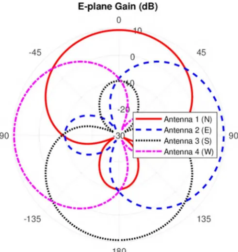
[image:3.595.307.553.80.340.2]For this paper four directional, three-element Yagi antennas (pointing N, E, S and W), as shown in Figure 1, were used. The antenna patterns, determined by numerical simulation using CST microwave studio [13], are shown in Figure 2. The antennas have a maximum gain of 9.37dBi.
[image:3.595.41.292.554.719.2]Figure 1: Simulation model of the antenna geometry showing four dipoles with reflector and director elements.
Figure 2: Polar plot of antenna E-plane patterns showing the extent of overlap.
If a hub is equipped with directional antennas, each connected to its own transceiver, then, one envisages the following performance improvements:
• Improved range or lower transmit power operation for the nodes due to increased antenna gain at the hub compared with the omni-directional case;
• Improved throughput as several packets may be simultaneously received by the hub. N.B. there must be some overlap between adjacent antenna beams in a practical system, so it is unlikely that adjacent antennas can transmit simultaneously. Similarly, packets from some nodes will be receivable on multiple antennas.
antenna choice is updated, and the data, which has already been received, can be discarded.
2.2 Analysis of throughput
Here we derive analytical expressions and compare the throughput of a directional multi-antenna array at hub with that of the single omni-directional antenna ALOHA protocol.
The throughput of pure ALOHA with a single antenna is
= (1)
where is the offered load for this case [12].
With antennas, where no-overlap exists between the identical antenna beams and if we assume the nodes are equally distributed between the M antennas, the system will behave as if there are M separate ALOHA systems. The offered load to each antenna is then 1/ of the total, and the overall throughput SMno is times larger than that of a single antenna:
= (2)
Each of the sectors will subtend an angle:
= degrees (3)
However, overlaps between antenna patterns will occur in any practical systems and packets from nodes in the overlapping regions may be received by two (or more) antennas, thereby resulting in the increasing probability of collision. If the angle over which each antenna can successfully receive packets is
degrees, then each antenna will see its offered load increased by a factor of times the case with no overlap where:
= (4)
Also, a proportion of the packets will be received by more than one antenna which further reduces the effective throughput by the factor . Therefore, the overall throughput will be:
= = (5)
In order to determine , we must consider the required signal-to-interference ratio (SIR). If we assume all nodes have a transmit power adjusted to give a constant signal at the hub, then a packet from a node on antenna boresight ( = 0 ) can be interfered with by a node at an angle less than /2 , which is the angle where the antenna gain has dropped by an amount equal to the required SIR:
( /2) = (0) dB (6)
where ( ), is the antenna gain at the angle from boresight. A node at the sector edge ( /2) can be interfered with by
nodes at a wider range of angles. Once the angle of the interferer has increased until the gain has fallen from the value at /2 by an amount equal to the SIR, then its signal is too small to interfere and cause a collision. We define this as so that :
( /2) = ( /2) dB (7)
[image:4.595.308.550.247.434.2]For the example in this paper, the required SIR is 10.6 dB, which with = 4, and the antennas used, gives /2 = 70 , and /2 = 81 as shown in Figure 3.
Figure 3: The antenna gain, relative to boresight for = 4, at the sector edge ( /2), the SIR limit for boresight node ( /2), and the SIR limit for node at the sector edge ( /2).
[image:4.595.304.555.522.733.2]3 Simulation
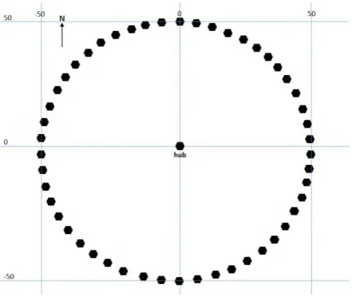
[image:5.595.45.292.371.564.2]In order to evaluate the merit of the proposed approach, we consider a simple scenario with a ring formation of 50 sensor nodes evenly distributed around a central hub station with the radius of 50m (Figure 4). The sensor nodes are equipped with an isotropic antenna with the transmission power of 0.01W and gain of 0dBi. The hub is equipped with four antennas (pointing N, E, S and W, with the beam pattern as shown in Figure 3). We consider free space propagation between the sensor nodes and the hub station. Packet reception is governed by the received SIR level, assuming uncoded binary phase shift keying (BPSK) modulation. A look up table is used to ascertain the bit error rate (BER) corresponding to a received SINR level and the BER value is used to determine whether each individual bit is received in error (based on generation of a random variable in the range 0 to 1 and comparison with the BER threshold). Packets are received if there are no bit errors (i.e. BER = 0). If the interference level changes during packet reception, the BER value is updated for the appropriate packet segment(s). The key simulation parameters mirror those of an IEEE 802.15.4 compliant system, operating in the 2.4 GHz band, with the packet length of 1024 bytes, but without the complexities of spread-spectrum.
Figure 5: Throughput of ALOHA with = 1 and 4 hub antennas comparing theory with Riverbed Modeler 50 node simulation.
Figure 5 shows a comparison of the theoretical throughput of the standard, single antenna ALOHA model (assuming an infinite number of nodes and Poisson traffic); the result of a Riverbed Modeler simulation of 50 nodes equally distributed around the hub with four antennas, at equal distance; the throughput predicted using (5) with /2 = 81 . as predicted above; and a result using (5) which has been fitted to the Riverbed Modeler results by varying /2 to minimise the mean absolute error between the curves. The best fit curve predicts /2 = 82.3 , which is quite close to our empirical prediction above.
4 Conclusions and further work
An example of a WSN, by using a modified ALOHA protocol, with directional antennas on hub has been modelled using Riverbed Modeler and simulated with varying offered load. The performance of our proposed protocol with four antennas has a throughput of 2.17 times higher than the traditional ALOHA with a single antenna. It can be seen that the improvement in performance depends on the degree of overlap between the antenna patterns, therefore the antenna pattern is considered as an important factor.
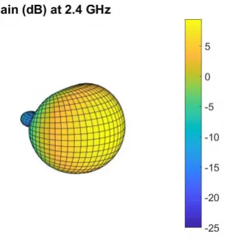
[image:5.595.374.539.448.625.2]The proposed protocol is based entirely on the use of directional antennas at the hub, where power consumption and complexity are less significant, without the need of compromising the energy consumption or the complexity of the sensor node. It also offers the possibility of improved range or lower node power consumption due to the increased gain of the hub antennas. If it were possible to reduce the antenna pattern overlap further, we note that the maximum throughput increases towards times that of simple ALOHA as approaches . Therefore, further work on antenna design may yield significant performance improvements. In addition, the analysis and simulations in this paper consider, what is effectively a two-dimensional scenario. In many situations, the full three-dimensional pattern, as shown in Figure 6, will be significant and will affect the degree of overlap. Further work is required to determine the effect of the 3-dimensional nature of the pattern in different scenarios.
Figure 6: 3D pattern for one of the Yagi antennas
References
[1] K. Hunchangsith, M. E. Bialkowski, M. Portmann, X. Liu, "Maximum Throughput of ALOHA Employing Multiple Antenna Technique", International Conference on Wireless Communications, Networking and Mobile Computing, pp. 1-4, (2009). [2] O. Bazan, M. Jaseemuddin, "A Survey On MAC
Protocols for Wireless Adhoc Networks with Beamforming Antennas", IEEE Communications Surveys & Tutorials, 14, pp. 216-239, (2012). [3] J. Chang, "A Multibeam Packet Satellite Using
Random Access Techniques", IEEE Transactions on Communications, 31, pp. 1143-1154, (1983). [4] A. Nasipuri, S. Ye, J. You, R. E. Hiromoto, "A MAC
protocol for mobile ad hoc networks using directional antennas", IEEE Wireless Communications and Networking Conference, pp. 1214-1219 (2000). [5] X. Y. R. R. Choudhury, R. Ramanathan and N. H.
Vaidya, "Using directional antennas for medium access control in ad hoc networks", International Conference on Mobile Computing and Networking, pp. 59 - 70, (2002).
[6] N. S. Fahmy, T. D. Todd, "A selective CSMA protocol with cooperative nulling for ad hoc networks with smart antennas", IEEE Wireless Communications and Networking Conference, pp. 387-392, (2004).
[7] S. Atmaca, C. Ceken, I. Erturk, "Capacity Enhancement in Wireless Networks using Directional Antennas ", International Journal of Electronics and Communication Engineering, 2, (2008).
[8] J. Ward, R. T. Compton, "High throughput slotted ALOHA packet radio networks with adaptive arrays",
IEEE Transactions on Communications, 41, pp. 460-470, (1993).
[9] S. Mudliar, L. S. Pillutla, "Performance evaluation of memory guided directional MAC protocol in the presence of relays", IEEE International Conference on Advanced Networks and Telecommunications Systems (ANTS), pp. 1-6, (2017).
[10] R. Ramanathan, "Antenna Beamforming and Power Control for AD HOC Networks", Mobile Ad Hoc Networking, IEEE Press, pp. 139-174, (2004). [11] Riverbed Modeler. Available:
https://www.riverbed.com/gb/products/steelcentral/st eelcentral-riverbed-modeler.html
[12] L. Kleinrock, F. Tobagi, "Packet Switching in Radio Channels: Part I - Carrier Sense Multiple-Access Modes and Their Throughput-Delay Characteristics",
IEEE Transactions on Communications, 23, pp. 1400-1416, (1975).
[13] CST Studio Suite. Available: