Electrolyte: Anodization Current Response and Solvation Effect
Sorachon Yoriya1,* and Ningzhong Bao2
1
National Metal and Materials Technology Center, 114 Thailand Science Park, Pahonyothin Road, Khlong 1, Khlong Luang, Pathum Thani 12120, Thailand
2
State Key Laboratory of Materials-Oriented Chemical Engineering, College of Chemistry and Chemical Engineering, Nanjing University of Technology, Nanjing 210009, China
*
E-mail: [email protected]
Received: 18 August 2014 / Accepted: 20 September 2014 / Published: 29 September 2014
This work report on the fabrication of titania nanotube array film anodized in a fluoride-based electrolyte mixture of dimethyl sulfoxide and ethanol. Optimization of the anodization parameters has been examined and reported in a 3D surface plot, with the achieved result that the improved nanotube length is up to six times, as using the similar conditions reported in the previous work (Ruan et al. 2005 J. Phys. Chem. B 109, 15754.) With a systematically designed experiment, we demonstrate the more insight into interaction and solvation effect in the anodization electrolyte, particularly elucidating how electrolyte history and properties has a strong effect on the anodization current behavior. In a parallel illustration of nanotube length mapping analysis, we also investigate evolution of nanotube morphology in freshly prepared and used electrolytes in relation to the change in real-time current density for titanium anodization in dimethyl sulfoxide/ethanol mixture. It is believed that reactivity of DMSO could be inhibited by the effect of ethanol incorporation that could possibly be a drawback in slowing down those ion movements in the electrolyte, consequently affecting the pore growth and thus the nanotube length.
Keywords: TiO2 nanotube array films, electrochemical anodization current response, solvation,
dimethyl sulfoxide electrolyte
1. INTRODUCTION
enables fabrication of free-standing, self-supportive membranes that can be used for biofiltration.[3, 4] In contrast, nanotubes grown from dimethyl sulfoxide (DMSO) electrolytes have weak tube-to-tube binding, as well as weak adhesion to the underlying barrier layer.[5] Hence the DMSO synthesized tubes can be easily dispersed enabling their use, for example, in enhancing blood clotting to control hemorrhage.[6] Furthermore, A mixture of DMSO and ethylene glycol was found to recently give a single-walled morphology of titania nanotubes with significantly enhanced electronic properties for higher efficiency dye-sensitized solar cells.[7] Tuning effects of 12% DMSO content in ethylene glycol or glycerol matrix on nanotube length, wall thickness, dimension and morphology was also studied; incorporation of DMSO was found to display a high sensitivity to hydrogen at room temperature compared to the condition with the absence of DMSO.[8]
The anodic formation of TiO2 nanotube arrays in DMSO were studied and first reported by
Ruan et al in 2005.[5] Ruan and co-workers reported the synthesis of TiO2 nanotube arrays in a
fluorinated DMSO based electrolyte.[5] Fabrication in DMSO:EtOH (1:1)4.0% HF electrolyte at 20 V for 70 h at room temperature, a maximum nanotube length of 2.3 µm ( 0.3) was obtained. The nanotube array film obtained from this work appears to have debris clogging the nanotube pores. Washing the as-anodized samples in DMSOHF solution following with sonication could help to remove such debris, consequently leading to the nanotubes with open pores. However, the tube length obtained from Ruan’s work is still shorter than the several micron-length one obtained from the aqueous electrolytes using a suitable pH.[9] An attempt has been pursue on the use of DMSO to fabricate the titania nanotube array films grown in the electrolyte with the condition in absence of ethanol; the significant increase in tube length was obtained. According to this evidence, it has been presumed that ethanol might probably have a significant effect of limiting the nanotube length; however, this point of question has not yet identified. Thus, the focus of this study is to clarify this question. With a set of designed experiment considering how to systematically manipulate the synthesis parameters, we aim to better understand the electrolyte behavior through considering solvent interactions and solvation effect. This work also present the study of anodization current behavior in DMSO containing ethanol electrolye and clarify why titanium anodization in this mixture results in a patterned current-time behavior different from those observed in other electrolyte systems.
The typical anodization current-time responses during anodization in aqueous electrolytes [10] and organic electrolytes, such as ethylene glycol/ NH4F/H2O, formamide/H2O containing different
cationic species, [3, 5, 11-15] as a function of voltage and fluoride species have been extensively reported in a combination study on mechanism of nanotube formation. The current behavior observed for the organic electrolytes is mostly similar to the typical one observed for the water-based electrolyte. Particularly for that observed for dimethyl sulfoxide (DMSO), fluctuation with dynamics pattern of anodization current behavior is usually seen; however, such unclear fluctuation behavior over a period of anodization time has never been well clarified. Thus, this report focuses on showing a systematic result obtained from a designed experiment in order to better understand the formation mechanism of nanotube array growth; evolution of nanotube morphology relating to the change in current density for titanium anodization in DMSO are to be investigated.
Titanium sheet (250 µm, 99.7%, Sigma-Aldrich) were rinsed with acetone, soap and deionized water prior to potentiostatic anodization, and the platinum foil was used as a counter electrode. It is necessary that the distance between the two electrodes is maintained constant; herein the 2-cm distance was fixed.[22] Anodization using different inter-electrode spacing would lead to variation in morphology of the resulting nanotube arrays, with closer spacing leading to the stronger electric field strength hence facilitating the electrochemical anodization process.[23] The anodization current was monitored using a Keithley (model 2000) digital multimeter interfaced with a computer. In the experiment, the electrolyte base was prepared by mixing dimethyl sulfoxide (DMSO; 99.9%, Sigma-Aldrich) and ethanol in a 1:1 ratio, a fixed fluoride content of 4% hydrofluoric acid (HF; 48 % aqueous solution, JT Baker). Anodization was performed in different conditions; i.e. varying anodization voltage, time and electrolyte history. The dipped area of the foil samples into electrolyte was fixed at 3.0 cm2. After anodization, the samples were rinsed thoroughly with isopropanol and blow-dried with 99.99% pure nitrogen. The anodized nanotube array films were characterized by field emission scanning electron microscope (FE-SEM, Leo 1530).
3. RESULT AND DISCUSSION
3.1 Optimization of Anodization Parameters
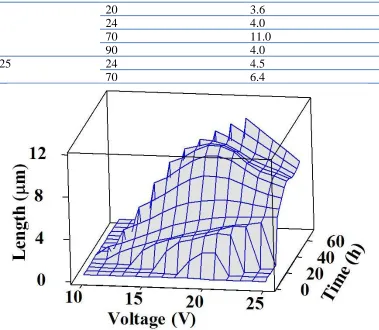
The evolution of surface morphology was investigated as a function of applied voltage and anodization time. Table 1 shows the effect of anodization voltage and time on the nanotube length. Compared to the previous report, the maximum tube length of 11 µm is almost five times longer than the 2.3-µm length reported by Ruan, as using the anodization conditions based on those used in Ruan’s report. [5] Noted that, the 11-µm length sample was obtained from using the freshly prepared electrolyte. When using the previously used electrolyte in which conductivity is relatively higher, the tube length is known to significantly decrease. [15, 24]
Table 1. Tube length of TiO2 nanotube arrays obtained from anodizing in the fresh DMSO:EtOH
(1:1)4.0% HF electrolytes at different voltages and different anodization times.
Voltage (V) Anodization time (h) Tube length (µm)
10 24 0.5
20 1 0.4
20 3.6
24 4.0
70 11.0
90 4.0
25 24 4.5
[image:4.596.111.490.69.399.2]70 6.4
Figure 1. A 3D-surface plot of TiO2 nanotube length as functions of anodization voltage and time for
those data presented in Table 1.
3.2 Evolution of TiO2 Nanotube Array Films Grown in Fresh and Used Electrolytes
(a)
(b)
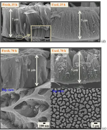
(d)
[image:6.596.126.474.66.491.2](e)
Figure 2. FESEM images showing cross-sectional and top views of TiO2 nanotube arrays fabricated
from the ‘fresh-prepared electrolytes’ (left, DMSOEtOH electrolyte containing 4.0% HF at 20 V) and the ‘used electrolytes’ (right, reanodizing the first used DMSOEtOH electrolyte containing 4.0% HF (20 V, 70 h) as the second time at 20 V). For both fresh and used electrolytes, the anodized nanotube array films were collected at different anodization times; i.e. (a) 1h, (b) 10 h, (c) 20 h, (d) 35 h, and (e) 70 h.
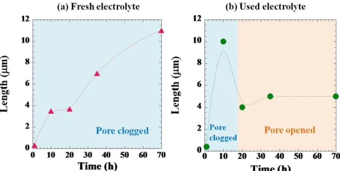
Figure 3. Variation of nanotube length as a function of anodization time of TiO2 nanotube arrays
obtained from anodizing in (a) fresh electrolytes ( ) and (b) used electrolytes ( ). Electrolyte and anodization conditions for figures (a) and (b) are as same as those explained in Figure 2.
In Figure 1, the surface plot of titania nanotube length tends to shift to the higher regime of anodization voltage and time. Through optimizing the anodization parameters, this particular mixture of electrolyte allowed the optimum length of nanotubes to be obtained, implying that the electrolyte properties have a meaningful effect on the nanotube length. In other words, the effect of the electrolyte nature is attributed to play a predominant role in governing the growth kinetics of nanotube.
In the EtOH-H2O-DMSO mixture, EtOH has a proton affinity (185.6 kcal mol-1)[25] higher
than water (38.1 kcal mol-1)[26] and lower than DMSO (> 211 kcal mol-1);[27] hence EtOH can easily form the large protonated ethanol clusters (EtOH2+) in the mixture. The form of EtOH2+ is a little more
acidic than H3O+ and so the clusters can react selectively with DMSO. DMSO favors a specific and
strong interaction with a dipolar hydrogen bond donor like EtOH due to its strong hydrogen bond acceptor nature.[28] Accordingly, it is believed that reactivity of DMSO is reduced because of the solvation effect of ethanol clusters; as a consequence, mobility of transport ions could be decreased resulting in the reduced conductivity. Considering the solvents donor number (DN) value, DN is a measure of solvent polarity, with the high DN reflecting the high polarity of solvent. The DN also shows the ability of solvent to solvate cations, Mn+ and other Lewis acid.[29, 30] The DN of EtOH is higher than that of DMSO, implying that the dissolved Ti4+ ions and/or H+ are more likely to be solvated by EtOH with respect to DMSO. The fluoride ion can also have a strong association forming ion pairs with alcohol molecules, which makes it difficult to obtain the free F- available in the bulk aprotic solvent.[31] To this point of view, incorporation of ethanol into the DMSO could possibly be a drawback in slowing down those ion movements in the electrolyte, consequently affecting the pore growth. A key to increase the nanotube length is necessarily to reduce the chemical dissolution of the oxide at the pore mouth, while maintaining the active growth at the bottom of the pore. Thus, mobility and availability of F- and OH- at the oxide/electrolyte interface is essential in the oxide growth process.
Addition of water to the electrolyte ensures field assisted etching of the Ti foil at the pore bottom. The formation of the barrier oxide layer or the compact layer of TiO2 at the bottom of the
[image:7.596.134.465.71.238.2]
i.e. the S=O∙∙∙S=O bond between DMSO molecules tends to gradually break up and water molecules will subsequently insert or associate to the DMSO molecule.[33] The formation structures of water and DMSO molecules in the mixtures are shown in Figure 4.
Figure 4. Intermolecular associations between DMSO and water molecules in the mixed solution.24 (Me represents the methyl (CH3-) group in DMSO molecule).
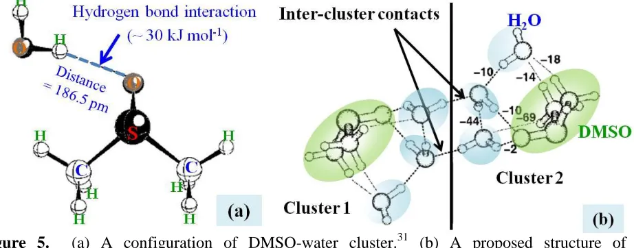
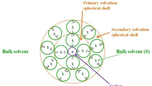
Kirchner and Reiher found that DMSO has strong preferential coordination with water forming clusters (see Figure 5); i.e. at least two molecules of water are added to a DMSO molecule in the first hydration shell and three to four in the outer adjacent shells as schematically shown in Figure 6.[34] Since the local electron-donating ability of DMSO is slightly greater than that of water, forming of a hydrogen bond between DMSO and water is attributed to the increased electrostatic contribution due to the stronger polarization of the oxygen atom in DMSO. Although the S═O bond in DMSO structure is strong, a slight S−O elongation could be observed for more coordination of water molecules.[35] When two or more water molecules interact with DMSO, the S−O∙∙∙H−OH distance (186.5 pm) is found to be longer such as 197 pm for 2 molecules having the relatively lower interaction energy between O∙∙∙H.[34]
[image:8.596.81.515.141.265.2] [image:8.596.65.526.520.701.2]
Figure 6. A schematic representation of a solvated metal ion or cation.
According to the strong interactions and the clusters forming in the electrolyte, the ion mobility and the mass transport to the electrode surface are consequently affected by these solvation effects.[36] In the case of large water content in the DMSOwater mixture, the solvation of F
will increase due to the increased hydrogen bond strength between F- and solvent molecules, thus inhibiting fluoride ion availability.[37] Furthermore, the reactivity of OH- may be reduced to some extent with larger water composition because water can effectively stabilize the anions by hydrogen bonding; see Figure 7. The activity of OH- in the mixture of DMSO/water solutions increases with increasing DMSO composition.[38] In the oxide growth process, the hydroxyl ion (OH-) is an essential source for the oxidation reaction.
Figure 7. Three possible arrangements of three water molecules to a hydroxyl ion (OH-).34
3.3 Analysis of Anodization Current Behavior in Freshly Prepared DMSO/EtOH Electrolytes
[image:9.596.166.429.73.221.2] [image:9.596.86.522.436.592.2]
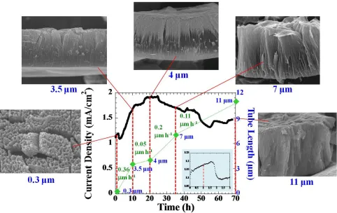
rapidly where the coating ratio increases and the film becomes denser. Noted that the coating ratio is the ratio of the coating weight to the metal loss.[39] At this first stage, the oxide formation rate should dominate the process.
In the first 3 h, The oxide layer becomes more porous forming the fine-featured nanochannels downward to the metal substrate. During this time, the current density decreases, indicating that the oxide dissolution rate starts to arise that thins the barrier oxide layer. Once the current reaches it equilibrium at about 3 h, the current starts to increase again due to the electric field effect. The field-assisted electrochemical process will try to adjust itself to a new equilibrium until it reaches the maximum point of the second hump. Each individual path further propagates through the barrier oxide layer forming the larger pore heads. The oxide film with 3.5-m length was obtained after 10 h anodization duration. The increasing slope during 3-10 h is higher than that of the first 1.5 h duration; i.e. 73.3 mA cm-2 h-1 and 63.3 mA cm-2 h-1, respectively. The steeper slope means that more ionic species pass across an area of the oxide layer, while the barrier oxide thickness tends to be thicker because of the dominating oxidation reaction.[40]
While the oxide growth continues to propagate during 10-20 h, the rate of ion penetration through the oxide layer slows down with increasing film thickness; thus the oxide formation rate in turn tends to decrease accordingly. After 20 h, a slightly thicker film of 4 m was obtained. After 24 h, the process is trying to adjust itself by transferring the non-uniform porous oxide structure into the more homogeneous pore formation. While the current density gradually decreases, the tube grows continuously from 4 m to 7 m at 35 h and from 7 m to 11 m at 70 h; that is, the growth rates decrease with anodization time that are 0.2 m h-1 and 0.11 m h-1, respectively. Small fluctuations are observed due to the non-uniform pore penetration in both lateral and downward directions.[10] Whereas the large fluctuation is probably because the steady-state pore formation is disturbed.
3.4 Analysis of Anodization Current Behavior in Used DMSO/EtOH Electrolytes
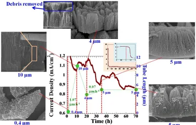
The anodization current behavior of the used electrolyte shown in Figure 9 is broadly similar to that of the fresh electrolyte as shown in Figure 8 for the fresh electrolyte. After 1.5 h, the current decreases rapidly showing the fast speed of the oxide formation. The growth rate (1.07 m h-1) is greater than that of the fresh electrolyte (0.36 m h-1) in Figure 8. During this time, the oxide film grows continuously from 0.4 m to 10 m at 10 h. In the highlighted box of the 10-m image, the pore formation revealed the fine-featured nanochannels to be observed; each individual nanotube cell is not yet separated from each other completely. The oxidation and the oxide etching processes are more significant in the downward direction.
Figure 8. A current density for titanium anodization in a fresh-prepared electrolyte (DMSOEtOH (1:1)4% HF) using 20 V and 70 h, with the overlay FESEM images of the as-anodized TiO2
nanotube array films obtained at different anodization.
The sudden increase of current density seen before 20 h is probably due to the debris collapse.[41] Thus, it is possible that the open top surface will allow more diffusing ions in the electrolyte to penetrate more deeply to the bottom of the arrays. As a result, the oxidation reaction is enhanced and then the current starts to rise again. From 20 h to 70 h, there is a slight increase in tube length from 4 m to 5 m, respectively. This clearly indicates that the anodization duration did not improve the nanotube length. For long anodization duration, the chemical dissolution is believed to dominate the process due to the electrolyte conductivity that increases with time and consequently determines the oxide growth process.
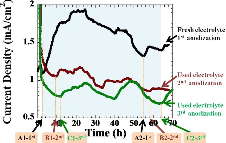
Figure 10 shows the overlay plot of the anodization currents obtained from the fresh electrolyte and the used electrolytes. In fresh electrolyte, two humps of current density are always observed for the anodization of titanium in DMSOEtOH electrolytes, when the zenith of the second hump normally locates in the higher current region compared to that of the first hump. After the equilibrium point of the lowest current density (A1−1st
), the overall process is governed by the oxidation reaction; the hemi-spherical shape of pore heads becomes larger. The tube length continuously increases with anodization time.
In a used electrolyte, the end point of the first hump delays to the longer anodization time compared to that of the fresh electrolyte. The point B1−2nd appears at the time sooner than the point C1−3rd
[image:11.596.60.542.68.372.2]
Figure 9. A current density for titanium anodization in a 2nd-time used electrolyte (after the electrolyte in Figure was first used), using 20 V and 70 h, with the overlay FESEM images of the as-anodized TiO2 nanotube array films obtained at different anodization time.
Compared the points A1−1st
of fresh electrolyte to B1−2nd and C1−3rd of used electrolytes, A1−1st
reaches the equilibrium faster than those two points of the used electrolytes. This could be explained that the pore pitting process for the fresh electrolyte reaches the stable state faster than that of the used electrolytes before transferring into a new equilibrium in the second hump. In the fresh electrolyte, it is probably due to the significant effect of diffusion limit in the long pore channels across the oxide film.[42] For longer anodization durations, the diffusion controlled process may also affect the anodization current leading to the similar dynamic pattern; i.e. after ~ 50 h the point A2-1st also turns into its new equilibrium sooner than B2-2nd and C2-3rd.
Several humps or current fluctuation are obviously seen in the used electrolytes. This is probably because of many possible effects of higher electrolyte conductivity, debris collapse, self-adjusting anodization current resulting from the change in electrolyte properties during anodization.[43] Hassan and co-workers also observed the current fluctuation for titanium anodization in high conductivity electrolytes containing 2-propanol/NH4F/H2O.[32] Additionally, in some literatures the so-called
current oscillation was observed in the electrolyte containing strong acid such as H2SO4, normally
[image:12.596.98.500.73.330.2]Figure 10. An overlay plot of anodization currents obtained from the fresh electrolyte (black-colored line) (DMSOEtOH (1:1)4.0% HF) and the used electrolytes. History of the second-time used electrolytes is that after the first-time anodization (20 V, 70 h) using the fresh-prepared electrolyte, this electrolyte was then reused as the second-time anodization (brown-colored line) at 20 V and 70 h. Whereas the third-time used electrolyte is that, the electrolyte after the second anodization was reused as the third-time anodization (green-colored line).
3.5 Effect of Acid Additive in Fresh DMSOEtOHHF Electrolyte on Anodization Current
This work also investigated the effect of acid on the anodization current behavior of Ti anodization in the DMSO/EtOH/HF electrolyte. Herein the trace amount of nitric acid was added. The solution is not only contain more dissociated protons, but also contain the NO3- species contributing
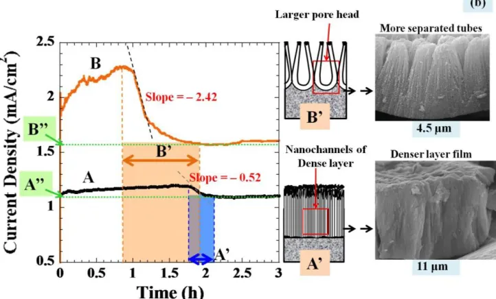
Figure 11. Current-time responses obtained from anodization of a Ti foil samples in DMSO:EtOH (1:1)4.0% HF electrolytes (solution A). For solution B, the electrolyte condition is the same as solution A, only a 10 L HNO3 is added into it. Both electrolytes were anodized at 20 V for 70
h. (a) An overlay of the current-time responses of both solutions A and B during anodization over 70 h. (b) A magnified plot of figure (a) showing the slope determination (left), FESEM images of the resulting nanotube array films (right), and the proposed schematic drawings (middle) showing the formation of nanopores during the growth stages of A’ and B’ for solution A and B, respectively.
As shown in Figure 11 (a), the current density behaviors of the electrolytes both with and without acid addition seem to be similar. The current density during the first hump in Figure 11 (a) was magnified and shown in Figure 11 (b). The decreasing current density is an indication of the oxide formation rate at the bottom of the nanotube arrays, where the dissolution at the top end of nanotube is negligible.[41] The larger slope means a faster rate of oxide pore formation. As highlighted in colors, the pore formation duration of the acid-added electrolyte covers a longer period of time; i.e. the distance B’ is larger than A’. Due to the effects of the increased proton concentration enhancing electrolyte conductivity, this indicates that addition of nitric acid to the solution B is more effective in penetrating the oxide nanochannels. Thus, it was expected that the solution B should also provide the nanotubes with a larger pore size. The behavior that the current drop with extended anodization time is typically observed in the oxide formation in acidic electrolytes with 3-10 % acid contents; the plot is available elsewhere.[45]
[image:14.596.118.479.78.296.2]the anodization current behavior relates to the formation of nanotube arrays, when the films were grown under different anodizing conditions. The interaction and solvation effect happening in the anoization electrolyte were found to play important roles in controlling ion mobility, nanotube growth rate and thus tube length. Analysis of current transients, particularly in the early stages of nanotube growth process, agrees well with the proposed models[41, 45] for diffusion controlled growth of nanotubes.
ACKNOWLEDGEMENTS
S. Yoriya acknowledges the Ceramics Technology Research Unit, National Metal and Materials Technology Center (MTEC), Thailand, for supporting us funding. Partial support of this work through the Material Research Institute (MRI), Department of Materials Science and Engineering, the Pennsylvania State University USA, is also gratefully acknowledged.
References
1. M. Paulose, K. Shankar, S. Yoriya, H. E. Prakasam, O. K. Varghese, G. K. Mor, T. A. Latempa, A. Fitzgerald and C. A. Grimes, J. Phys. Chem. B 110 (2006) 16179.
2. S. Yoriya, W. Kittimeteeworakul and N. Punprasert, J. Chem. Chem. Eng. 6 (2012) 686.
3. H. E. Prakasam, K. Shankar, M. Paulose, O. K. Varghese and C. A. Grimes, J. Phys. Chem. C 111 (2007) 7235.
4. M. Paulose, H. E. Prakasam, O. K. Varghese, L. Peng, K. C. Popat, G. K. Mor, T. A. Desai and C. A. Grimes, J. Phys. Chem. C 111 (2007) 14992.
5. C. M. Ruan, M. Paulose, O. K. Varghese, G. K. Mor and C. A. Grimes, J. Phys. Chem. B 109 (2005) 15754.
6. S. C. Roy, M. Paulose and C. A. Grimes, Biomaterial. 28 (2007) 4667.
7. H. Mirabolghasemi, N. Liu, K. Lee and P. Schmuki, Chem. Comm. 49 (2013) 2067. 8. Y. Ge, W. Zhu, X. Liu and S. Liu, J Nanosci. Nanotechnol. 12 (2012) 3026.
9. Q. Y. Cai, M. Paulose, O. K. Varghese and C. A. Grimes, J. Mat. Res. 20 (2005) 230. 10.V. P. Parkhutik and V. I. Shershulsky, Journal of Physics D: Appl. Phys. 25 (1992) 1258. 11.K. Shankar, G. K. Mor, A. Fitzgerald and C. A. Grimes, J. Phys. Chem. C 111 (2007) 21. 12.S. Berger, J. Kunze, P. Schmuki, A. T. Valota, D. J. LeClere, P. Skeldon and G. E. Thompson,
J.Electrochem. Soc. 157 (2010) C18.
13.S. Li, G. Zhang, D. Guo, L. Yu and W. Zhang, J. Phys. Chem. C 113 (2009) 12759.
14.D. Regonini, C. R. Bowen, R. Stevens, D. Allsopp and A. Jaroenworaluck, Phys. Stat. Sol. (a) 204 (2007) 1814.
15.K. Shankar, G. K. Mor, H. E. Prakasam, S. Yoriya, M. Paulose, O. K. Varghese and C. A. Grimes, Nanotechnol. 18 (2007) 065707; 11 pages.
18.G. K. Mor, O. K. Varghese, M. Paulose, N. Mukherjee and C. A. Grimes, J. Mat. Res. 18 (2003) 2588.
19.A. Ghicov and P. Schmuki, Chem. Comm. 20 (2009) 2791.
20.K. Shankar, K. C. Tep, G. K. Mor and C. A. Grimes, J. Phys.D Appl. Phys. 39 (2006) 2361. 21.A. Valota, D. J. LeClere, T. Hashimoto, P. Skeldon, G. E. Thompson, S. Berger, J. Kunze and P.
Schmuki, Nanotechnol. 19 (2008) 355701 (7pp).
22.S. Yoriya, International J. Electrochem. Sci. 7 (2012) 9454.
23.L. Sun, S. Zhang, X. W. Sun and X. He, J. Electroanal. Chem. 637 (2009) 6.
24.S. Yoriya, M. Paulose, O. K. Varghese, G. K. Mor and C. A. Grimes, J. Phys. Chem. C 111 (2007) 13770.
25.J. B. Nowak, L. G. Huey, F. L. Eisele, D. J. Tanner, R. L. Mauldin, C. Cantrell, E. Kosciuch and D. D. Davis, J. Geophys. Res. 107 (2002) 4363.
26.E. Pines and G. R. Fleming, Journal of Physical Chemistry 95 (1991) 10448. 27.F. Turecek, Journal of Physical Chemistry A 102 (1998) 4703.
28.R. A. Raphael, E. C. Taylor and H. Wynberg, Advances in Organic Chemistry: methods and results: Volume 5 Interscience Publishers, New York (1965).
29.J. R. Chipperfield, Non-Aqueous Solvents Oxford University Press, New York (1999). 30.D. C. Pope and W. T. Oliver, Canadian J. Compar. Med. Vet. Sci. 30 (1966) 3.
31.J. J. R. Pliego and D. Pilo-Veloso, Phys. Chem. Chem. Phys. 10 (2008) 1118.
32.F. M. B. Hassan, H. Nanjo, H. Tetsuka, M. Kanakubo, T. Aizawa, M. Nishioka, T. Ebina and A. M. Bond, J. Electrochem. Soc.156 (2009) K227.
33.A. Bertoluzza, S. Bonora, M. A. Battaglia and P. Monti, J. Ram. Spec. 8 (1979) 231. 34.B. Kirchner and M. Reiher, Journal of the American Chemical Society 124 (2002) 6206. 35.Y.-J. Zheng and R. L. Ornstein, J. Amer. Chem. Soc. 118 (1996) 4175.
36.W. S. MacGregor, Annals of the New York Academy of Sciences 141 (2006) 3.
37.A. Bhattacharya, K. Das, A. K. Das and K. K. Kundu, Bull. Chem. Soc. Jpn. (BCSJ) 54 (1981) 2194.
38.R. Stewart and J. P. O'Donnell, Canadian J. Chem. 42 (1964) 1681. 39.L. Young, Anodic Oxide Films Acadamic Press, New York (1961).
40.A. Valota, D. J. LeClere, P. Skeldon, M. Curioni, T. Hashimoto, S. Berger, J. Kunze, P. Schmuki and G. E. Thompson, Electrochim. Acta 54 (2009) 4321.
41.K. Yasuda and P. Schmuki, Electrochim. Acta 52 (2007) 4053.
42.R. B. Wehrspohn, A. P. Li, K. Nielsch, K. Mueller, W. Erfurth and U. Gosele, Highly Ordered Alumina Films: Pore Growth and Applications (Oxide Films in The Electrochemical Society Proceeding Series) PV 2000-4, Pennington, Marcel Dekker, New Jersey (2000).
43.D. D. Macdonald, Transient Techniques in Electrochemistry Plenum Press, New York (1977). 44.R. Beranek, H. Hildebrand and P. Schmuki, Electrochem. Sol. Stat. Lett. 6 (2003) B12.
45.J. M. Macak, H. Tsuchiya, A. Ghicov, K. Yasuda, R. Hahn, S. Bauer and P. Schmuki, Curr. Op. Sol. Stat. & Mat. Sci. 11 (2007) 3.
46.N. Sato, Corrosion 45 (1989) 354.