Int. J. Electrochem. Sci., 8 (2013) 1434 - 1442
International Journal of
ELECTROCHEMICAL
SCIENCE
www.electrochemsci.orgShort Communication
Effects of H
2S-containing Corrosive Media on the Crystal
Structures of Corrosion Product Films Formed on L360NCS
Shuqi Zheng*, Liwei Liu, Chengshuang Zhou, Liqiang Chen, Changfeng Chen
State Key Laboratory of Heavy Oil Processing and Department of Materials Science and Engineering, China University of Petroleum, Beijing 102249, China
*
E-mail: [email protected]
Received: 4 November 2012 / Accepted: 5 December 2012 / Published: 1 January 2013
The hydrogen permeation behaviors of L360NCS carbon steel in different H2S corrosive media were studied by a high-temperature, high-pressure hydrogen permeation system. The corrosive media contained 5% NaCl solution, 5.0% NaCl and 0.5% CH3COOH solution(NACE-A solution), and the service working condition solution. The results show that the corrosion products of L360NCS carbon steel differ depending on the corrosive medium. SEM analysis shows that the differences among the morphologies of the corrosion products are significant. Bulk and needle-like crystals are very common. Further analyses by XRD, TEM, and other methods reveal that the crystal structures of the corrosion products are also different.
Keywords: hydrogen permeation, corrosive media, crystal structure, corrosion product films
1. INTRODUCTION
Pipeline steel failure results in oil and gas leakages, as well as in significant economic losses and casualties. Hydrogen-induced cracking (HIC) and sulfide stress cracking (SSC) are well-known hydrogen-related problems of pipeline steels exposed to hydrogen sulfide (H2S)-containing media[1-3]. Both HIC and SSC are due to the embrittlement phenomenon related to the trapping of H atoms generated during the corrosion of steel in H2S-containing corrosive media. Studies on hydrogen permeation are highly significant in understanding the corrosion mechanism as well as in solving the corrosion and cracking problems[4-7].
Anodic reaction: FeFe22e (1) Dissociation reactions: +
-2
H SH + HS (2)
HS-H + S+ 2- (3) Cathodic reaction: 2 H+2e2 H (atomic hydrogen)H2(gas) (4)
The H+ ions present in acidic solution or produced by dissociation reactions in neutral and alkali solutions combine at the cathode with the electrons released by the steel to form atomic hydrogen on the steel surface. The hydrogen atoms combine to form molecular gaseous hydrogen. However, the presence of H2S gas in acidic solution or hydrogen sulfide ions (HS-) in neutral and alkali solution reduces the rate of hydrogen gas formation on the steel surface[9].
Studies on hydrogen-induced damage mostly focus on the behavior of hydrogen atoms entering a metal, the crack propagation process, as well as the material performance degradation mechanism[10], and neglect the effects of corrosion product films on hydrogen permeation. Studies on the effects of corrosion product films in environmental media under high-pressure H2S and of the crystal structure of corrosion products on hydrogen permeation are limited.
Compared with metals, crystalline compounds have lower diffusion coefficients and higher diffusion activation energies. Ferrous sulfide, a crystalline compound, forms a dense protective film layer that significantly impedes hydrogen permeation [11,12]. Therefore, research on the effects of corrosion product films on hydrogen permeation is very promising. In this paper, different corrosion product films generated in a variety of corrosive media under a high-pressure hydrogen sulfide environment were studied. The effects of environmental media on the morphologies and crystal structures of corrosion product films, as well as on hydrogen permeation, were also discussed.
2. EXPERIMENTAL PROCEDURES 2.1 Specimens
The specimens were made of L360NCS. Their chemical composition (wt%) was as follows: C, 0.13; Si, 0.4; Mn 1.5; P, 0.02; S, 0.003; Cr, 0.3; and Fe balance. The specimens were heated from 920 °C to 950 °C and then air cooled.
2.2 Hydrogen permeation measurements
Studies on hydrogen diffusion in steels are extensive[13]. In the current work, a dual cell called a “modified Devanathan–Stachurski cell”[14] that is a popular equipment for testing hydrogen diffusion behavior, was used. The electrolytic cell of the dual cell was replaced by a high-temperature, high-pressure autoclave. The sketch of the equipment for testing hydrogen permeation was described in reference [15]. Hydrogen permeation experiments under high pressure were performed with the improved device.
[image:3.596.170.428.308.508.2]3. RESULTS AND DISCUSSION 3.1 Hydrogen permeation curve
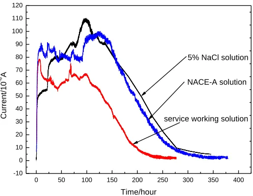
Figure 1. Hydrogen permeation current curves in the three different corrosive media.
Fig. 1 shows the hydrogen permeation curves of L360NCS carbon steel in three different corrosive media with 1.0 MPa H2S at 25 °C: 5% NaCl solution, 5.0% NaCl and 0.5% CH3COOH solution (NACE-A solution), and the service working condition solution. It was found that the absorbed hydrogen content reached maximum values then gradually decayed with time. The time dependence of the absorbed hydrogen content is attributable to the protective effect of the corrosion products on the steel surface[16]. Corrosion products can block hydrogen absorption because hydrogen diffusion is generally very slow through the non-metallic sulfide or oxide layer. Kimura et al. showed the hydrogen permeation rate reaches a maximum value within 10 h, then very quickly decreased at
0 50 100 150 200 250 300 350 400
-10 0 10 20 30 40 50 60 70 80 90 100 110 120
C
u
rre
n
t/
1
0
-6 A
Time/hour
high pressure H2S[17].
The time decay of the absorbed hydrogen content in the three curves can be explained based on the time-dependence of the hydrogen permeation. The change trends of the three curves demonstrate the hindering effect of the corrosion product films [18,19], which is determined by the morphology and crystal structure of the corrosion products [20]. In other words, the compositions, morphologies, crystal structures, and properties of the corrosion products formed in different corrosive media can affect hydrogen permeation.
By comparing the three hydrogen permeation curves, the service working condition solution is found to yield the maximum hydrogen permeation current and shortest duration. Thus, the hydrogen permeation ability was weakest in the service working condition solution which means that the corrosion productions formed on the surface of L360NCS exposed to service working condition pose higher protection. Some differences between the 5% NaCl and NACE-A solutions were observed in the hydrogen permeation curves. First, the hydrogen permeation current in the rising period is larger in NACE-A solution than in 5% NaCl solution, which can be attributed to the lower pH (2.7) of NACE-A solution. Second, the platform state in NACE-A solution has smaller volatility than 5% NaCl solution, which may be related to the composition of the corrosion product film. Third and last, the hydrogen permeation currents at the ends of the three hydrogen permeation curves decrease to a low value, which means that the corrosion product films have significantly hindered the process of hydrogen permeation. The reason is that the hydrogen product could effectively hinder the electrochemical reactions because the corrosion product films affect the diffusion process of ions, such as HS-, aqueous H2S, Cl-, etc[15].
3.2 SEM image analyses
The corrosion products on the sample surface differ with the change in corrosive media of H2S at an H2S pressure of 1.0 MPa and at 25 °C. Fig. 2 shows the morphology of the corrosion products of carbon steel L360NCS in the different corrosive media: 5% NaCl solution (Figs. 2a and 2b), NACE-A solution (Figs. 2c and 2d), and the service working condition (Figs. 2e and 2f).
The morphologies of the corrosion products in the three different corrosive media significantly vary. The corrosion product film formed in 5% NaCl solution is very compact and dense. The surface morphology of the film has two basic forms: needle-like (dominant) and bulk (small amount) crystals (Figs. 2a and 2b). The corrosion product film formed in NACE-A solution is more compact and dense. The surface morphology has only one basic form, i.e., bulk crystals (Figs. 2c and 2d). The corrosion product film formed in the service working solution is very loose. The surface morphology also has two basic forms: bulk crystals (on the matrix surface) and loose needle-like crystals (Figs. 2e and 2f).
H2S for the formation of fine grains of pyrrhotite. The needle-like corrosion production formed in the 5% NaCl solution was also found when the coupons were exposed in top-of-line corrosion experiments at 70oC and only 0.013mPa H2S for a 3 week exposure[22]
Figure 2. Different morphologies of the corrosion products of carbon steel L360NCS in different corrosive media with an H2S pressure of 1.0 MPa and at 25 °C. (a)(b) 5% NaCl solution, (c)(d) NACE-A solution, (e)(f) service working condition solution.
(a) (b)
(c) (d)
[image:5.596.116.483.147.664.2]
3.3 XRD and TEM analyses
Figure 3. XRD spectra of the corrosion product films in three different solutions.
The XRD patterns in Fig. 3 indicate that the corrosion product films all mainly consist of iron sulfide but differ in the crystal structures. A comparison of the curves in Fig. 3 shows that the compositions of the corrosion product films in the three different H2S solutions differ from one another. Mackinawite and troilite are the main compositions of the corrosion product films in 5% NaCl solution and the service working condition solution, whereas only mackinawite is contained in the NACE-A solution. Mackinawite is a common mineral composed of tetragonal crystals, whereas troilite is hexagonal. The different crystal structures of iron sulfides formed in H2S-containing corrosive media were described in detail in reference [23].
To study further the corrosion product films, the corrosion products were investigated by transmission electron microscopy (TEM). The TEM analysis results are shown in Fig. 4. Fig. 4(a) shows the TEM image of a corrosion product in 5% NaCl solution and the service working condition solution. The selected area diffraction pattern (SADP) in Fig. 4(b) indicates that the troilite phase exists in the corrosion products.
10 20 30 40 50 60 70 80
In te n si ty/ cp s
2Degree
1-Mackinawite 2-Troilite 3-Iron 1 1 1,2 2
2
2 2 11 1 3 11
3 3 3 2 3 11 1 1 1,2 2 3 2 2 3 11 5%NaCl solution NACE-A solution
service working condition solution
2 2
[image:6.596.133.447.115.381.2]
Figure 4. (a)(b) TEM images of the corrosion product troilite. (c)(d) HRTEM images of the corrosion product mackinawite.
Fig. 4(c) shows the TEM image of other corrosion products formed on the surface of L360NCS in the three different corrosive solutions. The SADP in Fig. 4(d) indicates that the mackinawite phase exists in the corrosion products. The inset of Fig. 4(d) shows the high-resolution transmission electron microscopy (HRTEM) images of the corrosion product mackinawite. The formation of the corrosion product mackinawite and its lattice fringes can be clearly seen. The spacing value is 0.297 nm, which well agrees with the (101) planes of mackinawite. The different crystal structures of iron sulfides, such as mackinawite and troilite, were also analyzed in reference[24].
Although they are composed of iron and sulfur elements, the crystal structures of the corrosion product films significantly vary [24,25]. The differences of the crystal structures of iron sulfide are due to the corrosive medium differences [26]. Based on the abovementioned studies and SEM analyses, the bulk crystal is inferred to be a kind of mackinawite and the needle-like crystal is a kind of troilite. The three kinds of mineral have different crystal structures, which also affect the hydrogen permeation to a
(a) (b)
[image:7.596.103.494.68.432.2]
certain extent. The relationship between the crystal structures and their abilities to inhibit hydrogen permeation can also be inferred.
4. CONCLUSIONS
(1) Corrosion product films can significantly inhibit the process of hydrogen permeation. (2) The morphologies and crystal structures of the corrosion product films vary in different corrosive media.
(3) Mackinawite and troilite are the main compositions of the corrosion product films in 5% NaCl solution and the service working condition solution, whereas only mackinawite is contained in NACE-A solution.
(4) The compositions, morphologies, crystal structures, and properties of the corrosion products can affect hydrogen permeation to a certain extent.
ACKNOWLEDGEMENTS
This work was financially supported by the Natural Science Foundation of China (No.51171208 and 51271201) and the Science Foundation of China University of Petroleum, Beijing (No. LLYJ-2011-41).
References
1. S. Zheng, Y. Qi, C. Chen and S. Li, Corros. Sci., 60(2012)59. 2. Y. Yao, L. Qiao and A. Alex, Corros. Sci., 53(2011)2679. 3. T. Hara, H. Asahi and H. Ogawa, Corrosion, 60(2004)1113.
4. J. Capelle, J. Gilgert, I. Dmytrakh and G. Pluvinage, Int. J. Hydrogen Energy, 33(2008)7630. 5. J. Kittel, V. Smanio, M. Fregonese, L. Garnier and X. Lefebvre, Corros. Sci., 52(2010)1386. 6. P. Novak, R. Yuan, B. Somerday, P. Sofronis and R. Ritchie, J. Mech. Phys. Solids, 58(2010)206. 7. H. Xue and Y. Cheng, Corros. Sci., 53(2011)1201.
8. M. Lucio-Garcia, J. Gonzalez-Rodriguez, M. Casales, L. Martinez, J. Chacon-Nava, M. Neri-Flores and A. Martinez-Villafane, Corros. Sci., 51(2009)2380.
9. W. Kim, S. Koh, B. Yang and K. Kim, Corros. Sci., 50(2008)3336.
10.S. Zheng, D. Wang, Y. Qi, C. Chen and L. Chen, Int. J. Electrochem. Sci., 7 (2012) 12857. 11. H. Ma, X. Cheng, G. Li, S. Chen, Z. Quan, S. Zhao and L. Niu, Corros. Sci., 42(2000)1669. 12.J. Tang, Y. Shao, J. Guo, T. Zhang, G Meng and F. Wang, Corros. Sci., 52(2010)2050. 13.G. Park, S. Koh, H. Jung and K. Kim, Corros. Sci., 50(2008)1865.
14.M. Davanahan and Z. Stachruski, J. Electrochem. Soc., 111(1964)619. 15.C. Zhou, S. Zheng, C. Chen and G. Lu, Corros. Sci., (2012), doi:
http://dx.doi.org/10.1016/j.corsci.2012.10.016
16.T. Omura, K. Kobayashi and M. Ueda, NACE corrosion, (2009)09102.
17.M. Kimura, N. Totsuka, T. Kurisu, T. Hane and Y. Nakai, NACE Corrosion, (1985)237.
Sci., 2(2007) 82.
19.A. Torres-Islas and J. Gonzalez-Rodriguez, Int. J. Electrochem. Sci., 4(2009)640. 20.F. Arjmand and A. Adriaens, Int. J. Electrochem. Sci., 7(2012)8007.
21.C. Ren, D. Liu, Z. Bai and T. Li, Mater. Chem. Phy., 93 (2005) 305. 22.S. Smith, B. Brown and W. Sun, NACE corrosion, (2011)11081. 23.D. Rickard and G. Luther, Chem. Rev., 107(2007)514.
24.D. Rickard and J. Morse, Mar. Chem., 97(2005)141.
25.B. Vargas-Arista, J. S. Romero, C. Angeles-Chavez, A. Albiter and J. M. Hallen, Int. J. Electrochem. Sci., 6(2011)367.
26.E. Diaz, J. Gonzalez-Rodriguez, R. Sandoval-Jabalera, S. Serna, B. Campillo, M. Neri-Flores, C. GaonaTiburcio and A. Martinez-Villafane, Int. J. Electrochem. Sci., 5(2010)1821.