This is a repository copy of
The COSINE-100 data acquisition system
.
White Rose Research Online URL for this paper:
http://eprints.whiterose.ac.uk/132786/
Version: Accepted Version
Article:
Adhikari, G., Adhikari, P., Barbosa de Souza, E. et al. (43 more authors) (2018) The
COSINE-100 data acquisition system. Journal of Instrumentation, 13. P09006. ISSN
1748-0221
https://doi.org/10.1088/1748-0221/13/09/P09006
This is an author-created, un-copyedited version of an article published in Journal of
Instrumentation. IOP Publishing Ltd is not responsible for any errors or omissions in this
version of the manuscript or any version derived from it. The Version of Record is available
online at https://doi.org/10.1088/1748-0221/13/09/P09006
Reuse
Items deposited in White Rose Research Online are protected by copyright, with all rights reserved unless indicated otherwise. They may be downloaded and/or printed for private study, or other acts as permitted by national copyright laws. The publisher or other rights holders may allow further reproduction and re-use of the full text version. This is indicated by the licence information on the White Rose Research Online record for the item.
Takedown
If you consider content in White Rose Research Online to be in breach of UK law, please notify us by
Prepared for submission to JINST
The COSINE-100 Data Acquisition System
The COSINE-100 collaboration
G. Adhikari,aP. Adhikari,aE. Barbosa de Souza,bN. Carlin,cS. Choi,dW. Choi,eM. Djamal,f
A. C. Ezeribe,gC. Ha,hI.S. Hahn,i A. J. F. Hubbard,bE.J. Jeon,hJ. H. JobH.W. Joo,d
W.G. Kang,hW.S. Kang,jM. Kauer,kH. Kim,hH.J. Kim,lK.W. Kim,dM.C. Kim,jN.Y. Kim,h
S.K. Kim,dY.D. Kim,a,hY.H. Kim,h,mV. A. Kudryavtsev,gH.S. Lee,hJ. Lee,hM.H. Lee,hK.
E. Lim,bD.S. Leonard,hR. H. Maruyama,bF. Mouton,gS. Na,hS.L. Olsen,hH.K. Park,h
H.S. Park,mJ.S. Parkh,o
K.S. Park,hW. Pettus,bH. Prihtiadi,f C. Rott,jA. Scarff,gN. J.
C. Spooner,gW. G. Thompson,bL. Yangn
aDepartment of Physics, Sejong University, Seoul 05006, Republic of Korea
bWright Laboratory, Department of Physics, Yale University, New Haven, Connecticut 06520, USA
cPhysics Institute, University of São Paulo, 05508-090, São Paulo, Brazil
dDepartment of Physics and Astronomy, Seoul National University, Seoul 08826, Republic of Korea
eKorea Institute of Science and Technology Information, Daejeon, 34141, Republic of Korea
fDepartment of Physics, Bandung Institute of Technology, Bandung 40132, Indonesia
gDepartment of Physics and Astronomy, University of Sheffield, Sheffield S10 2TN, United Kingdom
hCenter for Underground Physics, Institute for Basic Science (IBS), Daejeon 34126, Republic of Korea
iDepartment of Science Education, Ewha Womans University, Seoul 03760, Republic of Korea
jDepartment of Physics, Sungkyunkwan University, Seoul 16419, Republic of Korea
kDepartment of Physics and Wisconsin IceCube Particle Astrophysics Center, University of
Wisconsin-Madison, Wisconsin-Madison, 53706, USA
lDepartment of Physics, Kyungpook National University, Daegu 41566, Republic of Korea
mKorea Research Institute of Standards and Science, Daejeon 34113, Republic of Korea
nDepartment of Physics, University of Illinois at Urbana-Champaign, Urbana, Illinois 61801, USA
oPresent address: High Energy Accelerator Research Organization (KEK), Ibaraki 319-1106, Japan
E-mail: [email protected],[email protected]
Abstract: COSINE-100is a dark matter direct detection experiment designed to test the annual
modulation signal observed by the DAMA/LIBRA experiment. COSINE-100 consists of 8 NaI(Tl) crystals with a total mass of 106 kg, a 2200 L liquid scintillator veto, and 37 muon detector panels. We present details of the data acquisition system of COSINE-100, including waveform storage using flash analog-to-digital converters for crystal events and integrated charge storage using charge-sensitive analog-to-digital converters for liquid scintillator and plastic scintillator muon veto events. We also discuss several trigger conditions developed in order to distinguish signal events from photomultiplier noise events. The total trigger rate observed for the crystal/liquid scintillator (plastic scintillator) detector is 15 Hz (24 Hz).
Keywords: Dark Matter detectors (WIMPs, axions, etc.); Large detector systems for particle and
astroparticle physics; Data acquisition concepts; Detector control systems; Front-end electronics for detector readout; Trigger algorithm; Trigger concepts and systems
Contents
1 Introduction 1
2 Data Acquisition Modules and Trigger Conditions 2
2.1 Charge-Sensitive M64ADC for Liquid Scintillator and Muon Veto 2
2.2 Flash Analog-To-Digital Converter for Crystal Detectors 4
2.3 Trigger Condition, Trigger & Clock Board, and Dead Time 6
3 Other Electronics 8
3.1 Preamplifier 8
3.2 High Voltage Supply Module 8
3.3 Photomultiplier Tubes 8
4 Data Quality Monitoring 10
5 Summary 12
1 Introduction
The COSINE-100 experiment [1] is a joint effort between KIMS-NaI [2–4] and DM-Ice [5,6] to unambiguously test the claim of dark matter detection by the DAMA/NaI [7] and DAMA/LIBRA [8–
10] experiments with thallium-doped sodium iodide (NaI(Tl)) scintillating crystals. COSINE-100 is located at the Yangyang Underground Laboratory (Y2L), in the Yangyang pumped storage power plant, with 700 m minimum of rock overburden. The first phase of experiment with 106 kg of NaI(Tl) crystals began taking data in September 2016.
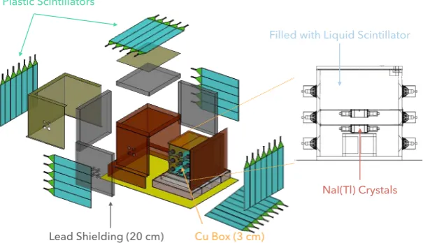
The COSINE-100 detector consists of eight NaI(Tl) crystals with a total mass of 106 kg, a 2200 L linear alkylbenzene (LAB)-based liquid scintillator (LS) veto for internal background suppression with coincidence event tagging [11] as well as cosmic-ray muons, copper and lead shielding, and 37 plastic scintillator (PS) panels that serve as an additional veto for cosmic-ray muons. Figure 1 shows a schematic representation of the COSINE-100 detector and shielding structure. A more detailed description of the detector can be found in [1].
A total of 16 3-inch photomultiplier tubes (PMTs) are attached to the crystals, with one PMT at each end of each crystal. The LS is contained in an acrylic-lined copper box, with 18 5-inch PMTs optically coupled to the acrylic box to detect photons from the LS veto. A total of 42 2-inch PMTs are attached to the plastic scintillators, two PMTs on each end of the five top panels and a single PMT for the rest.
Plastic Scintillators
Lead Shielding (20 cm) Cu Box (3 cm)
NaI(Tl) Crystals Filled with Liquid Scintillator
[image:4.595.148.451.119.293.2]40 cm
Figure 1. A schematic of the COSINE-100 detector, which includes an NaI(Tl) crystal array with a total mass of 106 kg, a 2000 L liquid scintillator veto, copper and lead shielding, and 37 plastic scintillators for muon detection.
2 Data Acquisition Modules and Trigger Conditions
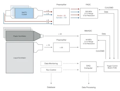
The data acquisition system of COSINE-100 consists of eight flash analog-to-digital converter (FADC1) modules, two charge-sensitive flash analog-to-digital converter (M64ADC2) modules, one trigger & clock board (TCB), four preamplifiers, a high voltage (HV) supply system, and Linux processors.
Liquid scintillator signals are amplified by a factor of 30 and fed into M64ADC modules, while the plastic scintillator signals are directly connected to M64ADCs (see Section2.1). Each of the 16 crystal PMTs provides two readouts (see Section3.3), a high-gain signal from the anode and a low-gain signal from the 5th stage dynode, that are digitized by FADC modules (see Section2.2). The anode signal is amplified by a factor of 30 and the dynode signal is amplified by a factor of 100. The 32 crystal signals, plus the 18 LS and 42 plastic scintillator PMTs amount to a total of 92 signal channels that are recorded by the DAQ system. The global trigger decisions are made by the TCB, which also synchronizes all of the module clocks (See Section2.3); the raw data are stored on the DAQ computer in ROOT format. Figure2 summarizes the overall data flow of the COSINE-100 experiment.
2.1 Charge-Sensitive M64ADC for Liquid Scintillator and Muon Veto
To collect data from the LS and plastic scintillator vetoes, two charge-sensitive M64ADC modules with a 64 MS/s sampling rate are used. Each M64ADC module has 32 channels with an input
1NKFADC500 module from NOTICE Korea: http://www.noticekorea.com
PreampliÞer FADC
Trigger Control
Board (TCB)
M64ADC
DAQ
Computer
Anode ! 30 Dynode ! 100
500 MS/s 2.5 V Range 12 bit Resolution
64 MS/s 2.0 V Range 12 bit Resolution NaI(Tl)
Crystal
Plastic Scintillator
Liquid Scintillator
Data Processing Data Monitoring
Run Control
Database
PreampliÞer
! 30
! 8
! 8
! 42
! 18
! 8
! 8
Data Data
CLK/CMD
[image:5.595.88.494.91.396.2]CLK/CMD
Figure 2. The COSINE-100 data flow diagram. A total of 76 PMTs send signals to two types of digitizers that are managed by a trigger control board. The digitized data are saved in the DAQ computer. A total of 32 FADC channels and 60 M64ADC channels are used. InfluxDB and Grafana are used for storing and visualizing the data.
dynamic range of 2 Vp p input and 12-bit resolution. A total of 60 PMTs, 18 from the LS and
42 from the PS, are connected to these modules with BNC-type input connectors. The 18 PMT signals from the LS veto detector are amplified by a factor of 30, while the 42 PMT signals from the PS muon panels are not amplified but are directly connected to M64ADCs. The local trigger information from the ADC modules is passed to the TCB where a global trigger decision is made, and the final data is transferred to the DAQ computer via a USB3 port.
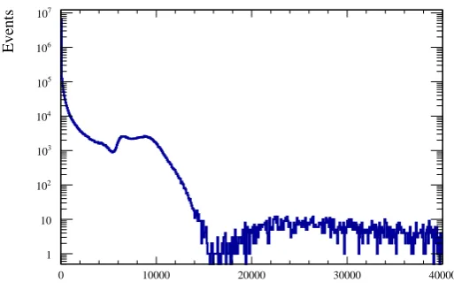
The charge-sensitive M64ADCs do not save the raw waveform data; instead, they provide the signal time and integrated charge according to a preset field programmable gate array (FPGA) setting. The analog signal input to the M64ADC is digitized every 16 ns and, when the FPGA receives a trigger, it digitizes the input signal integrated over the following 192 ns, returning the charge sum in ADC counts.This 192 ns M64ADC module integration time is longer than the decay time of the plastic scintillator and the LAB-based organic scintillator. Figure3displays an example spectrum of one of the top plastic scintillation panels.
Muon Top Side Charge Sum (ADC Counts)
0 10000 20000 30000 40000
Events
1 10
2
10
3
10
4
10
5
10
6
10
7
[image:6.595.152.409.98.262.2]10
Figure 3. The charge spectrum of one of the plastic scintillation panels for a live time of 120 hours. The charges from the two readout PMTs are summed and used to tag cosmic-ray muons. Events with integrated charges higher than 15,000 ADC counts are primarily due to muons, while lower energy events are mostly caused by Compton scatteredγ-rays.
outside the panels, we use an integrated charge trigger threshold of 4000 ADC counts (equivalent to approximately 125 pC); the integrated charge for most of the muon events is larger than 12,000 ADC counts (15,000 ADC counts for the top panels) [13]. For the top panels that have two readout PMTs, either one of the two PMTs is required to have an integrated charge of more than 4000 ADC counts to be triggered. When a muon traverses the COSINE-100 detector, it deposits energy in at least two different muon detector panels and, depending on its trajectory, the LS veto as well. In the cases where a muon stops inside the LS, it will deposit energy in a single muon detector panel and the LS veto. Therefore, we categorize two classes of events: those with at least two hit muon panels or at least one hit muon panel and one LS-veto PMT. When the integrated charge of a single channel is larger than the preset threshold, a coincidence window with a 400 ns width is opened. If any other channel triggers within this window, the M64ADC sends a trigger signal to the TCB. See Section2.3for more details on the TCB.
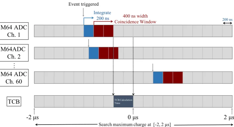
When the TCB sends a signal to the FADCs and M64ADCs to save an event, the M64ADCs open a 4 µs gate window, with the end of the TCB time in the middle of the window. Within this gate window, the M64ADC saves the maximum integrated charge values and its corresponding time for each channel. This time information is used for a passive data taking algorithm that is described in Section2.3. Figure4illustrates the trigger timing sequence for the M64ADC system.
2.2 Flash Analog-To-Digital Converter for Crystal Detectors
A total of eight 500 MS/s FADC modules are used to digitize analog signals from the NaI(Tl) crystals. Each FADC has four input channels with SMA-type connectors, with each channel having a dynamic range of 2.5 Vp pand a 12-bit resolution. Several functions are encoded in a FPGA on
M64 ADC Ch. 1
TCB Calculation Time
0 µs
-2 µs 2 µs
M64ADC Ch. 2
M64 ADC Ch. 60
É
TCB
Event triggered
Integrate
200 ns 400 ns width
Coincidence Window 200 ns
[image:7.595.104.495.84.296.2]Search maximum charge at [-2, 2 µs]
Figure 4. Trigger sequence for the M64ADC system. We require coincidence of at least two PMT signals that occur within 400 ns from either the LS veto or muon detector panels. Blue boxes represent the charge integration time and red boxes indicates the 400 ns-wide coincidence window. TCB time indicates the time needed for the TCB to interpret information received from the M64ADCs and generate a global trigger.
All COSINE-100 crystals have a 3-inch PMT attached to each end. The anode signal, which is sensitive at the single-photoelectron level, is the primary channel for the dark matter search analysis. The dynode signal records high energy events, such as those from alpha particles, which are used to improve the understanding of the internal backgrounds in the crystal such as the U, Th, and Pb contamination. Because the PMTs that are used (Hamamatsu R12669SEL) are known to suffer from non-linearity when the signal energy is higher than 1 MeV[2], the 5th dynode is used for signals above this energy. The PMT base structure was modified to extract both anode and the 5th dynode signals and connect them to separate FADC channels. A detailed discussion of this non-linearity is provided in Section3.3. For anode signals, a factor of 30 preamplifier is used to increase gain, with a linear response for energies up to 100 keV. A factor of 100 preamplifier is used for dynode signals and these have a linear energy response up to 3 MeV.
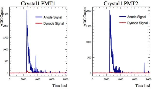
The waveforms from each of the two PMTs are recorded when there is a coincidence of high-gain anode signal larger than the preset threshold (6 mV, equivalent to 10 ADC counts or 0.2 photoelectrons) within a time window of 200 ns. The FADC module generates a trigger output signal if and only if both PMTs are triggered within the time window, as determined by the anode signal. The dynode signals are recorded when a global trigger is issued by the TCB. If any one of the eight crystals matches the coincidence condition, then a trigger signal is sent to the TCB (see Section2.3) and the FADCs save the waveforms of all the channels. The recorded waveform is 8 µs long, starting approximately 2.4 µs before the trigger occurs. The pre-trigger information is stored
in DRAM on the FADC board, which can store a waveform with up to 64 µs length.
Figure 5. Typical raw waveform of a triggered event from two PMTs in the same crystal, with both high-gain (anode) and low-gain (dynode) signals overlaid. The starting position of the waveform is set to 2.4 µs before
a global trigger time.
fluctuations, the contents of waveforms for both anode and dynode channels are suppressed to zero. This zero suppression algorithm is critical to reduce the data size, as when the DAQ is triggered typically only one or two crystals have generated signals whereas all other channels contain only baseline data. With this zero suppression, the data size can be reduced by∼80%.
To minimize noise from the electronics, we have bare ground cables wrapped around the DAQ and HV SHV/BNC connectors, which results in a noise reduction for the readouts. The peak-to-peak noise level is∼8 ADC counts on average (∼1.4 ADC counts or∼0.84 mV RMS) for the anode, and
∼20 ADC counts (∼2.3 ADC counts or∼1.38 mV RMS) for the dynode. Figure5 shows typical
waveforms of a triggered signal event from two PMTs in a crystal, with both anode and dynode readouts. This specific event corresponds to an energy of approximately 60 keV.
2.3 Trigger Condition, Trigger & Clock Board, and Dead Time
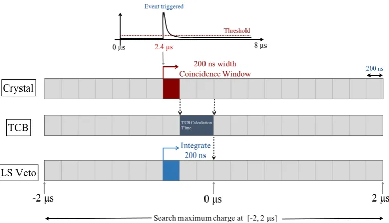
One of main roles of the LS veto is to tag internal background events originating from the crystals. If a crystal contains internal radioactive isotopes, such as 40K, γ rays from decay products can
deposit energy in a crystal and in the LS veto. It is particularly important to tag the40K background in COSINE-100, as the40K decay has a 3 keV X-ray line that is in the 2–6 keV energy range where the DAMA experiment observed an annual modulation [7–9]. This background can be suppressed by tagging coincident events of the 3 keV X-ray in the crystal and an accompanying 1460 keVγ-ray
in the LS or the other crystals.
TCB Calculation Time
0 µs TCB
Event triggered
200 ns width Coincidence Window
0 µs 8 µs
Crystal
LS Veto
Integrate 200 ns
2.4 µs
Search maximum charge at [-2, 2 µs]
-2 µs 2 µs
200 ns
[image:9.595.108.488.83.301.2]Threshold
Figure 6. Trigger algorithm for the case of passive data taking. Blue boxes represent the charge integration time and red boxes indicate the 200 ns wide coincidence windows. TCB time indicates the time needed for the TCB to interpret information received from the FADCs and M64ADCs and then generate a global trigger. We require coincident signals in both PMTs on a single crystal to occur within 200 ns of each other. If the trigger condition is satisfied, 8 µs of crystal waveform and M64ADC data for a single event is collected at the same time.
LS Total Charge (ADC Counts)
0 100 200 300 400 500
3 10
!
E
ve
nt
s
1 10 2 10
3 10
4 10
5 10
LS Total Charge
Figure 7. Liquid scintillator charge spectrum with two hours of crystal trigger. The charge from all 18 LS PMTs are summed.
describes the trigger algorithm for the passive data taking and Fig. 7 shows the total integrated charge of the LS veto with two hours of such passive data taking.
[image:9.595.152.414.429.598.2]veto are actively triggered when the trigger condition (multiplicity and threshold) is met. The FADC channels are not necessarily recorded in this case. This type of the global trigger is explained in Sec.2.1and in Fig.4.
These two global trigger paths between the FADC and M64ADC modules corresponding to the plastic scintillator veto are mutually independent and they both use multiplicity for deciding a global trigger; for M64ADC modules corresponding to the liquid scintillator veto, there is no independent trigger path as they are only passively triggered by crystal or plastic scintillator veto.
The global trigger is sent back to all FADCs and/or charge-sensitive M64ADCs at the same time depending on the type of trigger. The TCB has 40 RJ-45 type slots and the FADCs and M64ADCs are distinguished by slot number; and the communication between the TCB and FADCs or M64ADCs is done via Ethernet cables. The TCB also sends the TCB clock count to the modules which is used to synchronize the event time across modules.
When muons pass through a NaI(Tl) crystal, they cause a very high trigger rate (greater than 1 kHz) which exceeds the capacity of the DAQ system. Both the KIMS-NaI [2] and DM-Ice experiments [12] have measured elevated trigger rates of muon-induced events within NaI(Tl) targets. To prevent this, we apply a 1 ms hardware dead time to the FADC channel that generates a trigger. Because the the DAQ rate of the FADCs is about 15 Hz, the total dead time is only about 1.5%.
3 Other Electronics
3.1 Preamplifier
The preamplifier is designed to amplify the single photoelectron signals of a PMT without any loss of pulse information. As described in Section.2.1and2.2, signals from crystal PMTs are amplified by a factor of 30 (anode) and 100 (dynode); additionally, the LS PMT signal is amplified by a factor of 30. Customized preamplifiers with BNC connectors are used for these amplifications. The bandwidth of a PMT signal is about 100 MHz which requires a sampling rate greater than 200 MHz, which led us to use a 200 MHz bandwidth op-amp to amplify the signal.
3.2 High Voltage Supply Module
In order to supply high voltage to PMTs, CAEN high voltage supply modules are used. We use 8 CAEN A1535N HV supplies with two 24-channel and six 12-channel modules, which are all installed in a CAEN-4527 VME crate. All modules can supply voltages up to 3.5 kV with negative polarity, sufficient for all the PMTs used in the COSINE-100 detectors, as the highest magnitude of the voltage applied does not exceed 2500 V after the PMT gain correction. A high voltage scan was performed for all the channels prior to the physics run, followed by gain matching and light yield measurements[1].
3.3 Photomultiplier Tubes
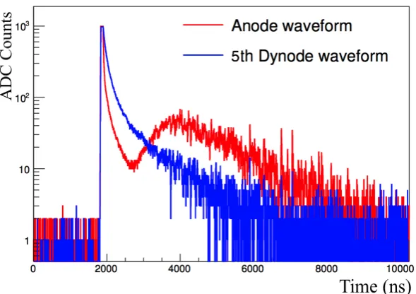
Figure 8. Raw waveform of an event read out by both the anode and dynode-stage 5. The anode waveform shows a distortion due to the non-linearity, whereas the dynode-stage 5 readout of the same event shows a normal waveform.
low-radioactivity material and exhibits a high quantum efficiency of 35%, leading to enhanced sensitivity for low energy events below 10 keV.
As descried in Section 2.2, signals from the anode and dynode of the PMTs attached to the NaI(Tl) crystals are taken simultaneously. To understand the internal backgrounds by looking at high energy alpha events, linearity over a wide energy range is important, but R12669SEL PMTs suffer from non-linear behavior at energies above a few MeV.
The R12269SEL PMT shows two characteristic charge non-linearity behaviors: one is mainly due to saturation of a pulse while the other is due to electron loss at the last stages of dynodes. It is known that space charges created near the final dynode stages may cause some electrons not to reach the next stage. To resolve this issue, a test setup with a modified PMT base circuitry was developed with different stages of dynode channel readout. When the waveforms of the anode and the dynode-stage 5 are compared in Fig.8, one can see that the waveform shape is distorted at the anode readout, but is preserved at the dynode-stage 5 readout. Figure 9also clearly shows a deformation in the correlation between charge sum and a pulse height in the anode channel, whereas in the dynode-stage 5 the linearity is maintained up to 1 MeV.
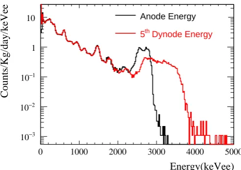
To check if the modified dynode channel can reproduce the anode signal with reasonable energy resolution, the energy spectrum of NaI(Tl) crystals has been studied with the test setup. Figure10
Pulse Height [ADC]
0 1000 2000 3000
Energy [keVee] 100 200 300 400 500 events β / γ events α
Pulse Height [ADC]
0 1000 2000 3000
[image:12.595.90.474.94.217.2]Energy [keVee] 1000 2000 3000 4000 5000 events β / γ events α
Figure 9. Energy distribution as a function of pulse height for anode channel (left) and 5th dynode channel (right). The anode signal shows non-linearity for high energy, whereas the dynode signal has a much improved linearity. Red data points are high energy alpha events.
Energy(keVee)
0 1000 2000 3000 4000 5000
Counts/Kg/day/keVee 3 − 10 2 − 10 1 − 10 1
10 Anode Energy
Dynode Energy
th
5
Figure 10. Energy spectrum of the anode and the 5th dynode signal. The anode signal shows saturation in high energy where the dynode-stage 5 signal extends up to 4 MeV. The dynode signal also shows that it can maintain an energy resolution as good as the one from the anode signal up to few MeV.
4 Data Quality Monitoring
[image:12.595.154.401.311.485.2]Figure 11. Example plots from the online data monitoring system. This set of plots are displaying energy spectra of two crystals with a pre-selection of triggered events. Blue points are the data from the 2 hours long subrun file, and red lines represent reference plots from a "good" subrun data.
02/03, 09h 02/04, 09h 02/05, 09h 02/06, 09h 02/07, 09h 02/08, 09h 02/09, 09h 02/10, 09h 02/11, 09h 02/12, 09h
Trigger Rate (Hz)
0 1 2 3 4 5 6 7 8 9
10 Crytal 1-4 Long-term Rate COSINE-100 Preliminary C1 C2 C3 C4 Crytal 1-4 Long-term Rate
02/03, 09h 02/04, 09h 02/05, 09h 02/06, 09h 02/07, 09h 02/08, 09h 02/09, 09h 02/10, 09h 02/11, 09h 02/12, 09h
Trigger Rate (Hz)
0 1 2 3 4 5 6 7 8 9
10 Crytal 5-8 Long-term Rate COSINE-100 Preliminary C5 C6 C7 C8 Crytal 5-8 Long-term Rate
02/03, 09h 02/04, 09h 02/05, 09h 02/06, 09h 02/07, 09h 02/08, 09h 02/09, 09h 02/10, 09h 02/11, 09h 02/12, 09h
Trigger Rate (Hz)
0 10 20 30 40 50 60 70
80 M64ADC Long-term Rate
COSINE-100 Preliminary M64ADC M64ADC Long-term Rate
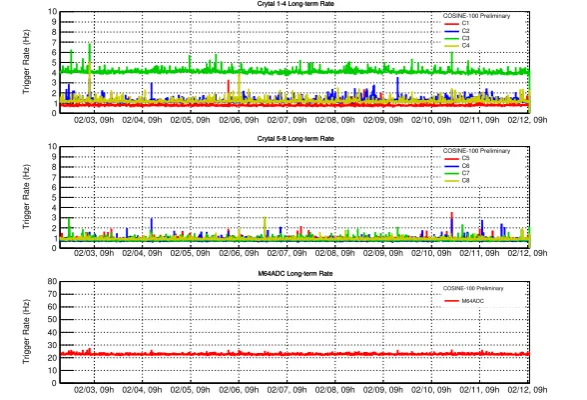
Figure 12. FADC (Crystal) and M64ADC (veto) trigger rates as functions of time, between Feb. 2, 2018 and Feb. 12, 2018. All the crystals and M64ADC PMTs show stable rates during this period, without any abnormalities. A higher rate in C3 (Crystal-3) than in other crystals is observed to be due to higher PMT noise. This plot is generated by the COSINE-100 monitoring system (see Section4).
account for time variation of the variables. Figure11shows example plots of one of the monitoring variables, the low energy spectrum with basic noise event removal. The blue line indicates data from the two-hour-long subrun file, whereas red lines represent the reference plots from good subrun data. Any deviation from the reference plot will be examined afterwards.
[image:13.595.150.444.350.550.2]also generated automatically: live-time, trigger rates of all crystals, M64ADC trigger rate, LS total charge, LS charge asymmetry, and muon event rate. For muon event rate monitoring, a higher level muon event selection, that includes both the charge and timing information, is applied to identify muon events among PS triggered events. These plots help to identify any long term trends in the data, such as a gradual increase in event rate. Figure 12 shows event rates for all 8 crystals and M64ADC PMTs, from February 2, 2018 to February 12, 2018.
5 Summary
The COSINE-100 detector was successfully constructed and commissioned by September 2016, and began its physics run in early October 2016. The data acquisition system for COSINE-100 is comprised of different ADC modules for the main crystal detectors and liquid or plastic scintillator vetoes. Trigger conditions and thresholds were carefully set to ensure stable data taking and effective coincident event selection, which is crucial for tagging the internal backgrounds of the crystals.
The total trigger rate observed for the crystal (plastic scintillator) detectors is 15 Hz (24 Hz). The current live time of the detector is>91%, where the∼9% down time originates primarily from
calibrations and maintenance downtime.
Acknowledgments
References
[1] G. Adhikariet al.[COSINE-100 Collaboration],Initial performance of the COSINE-100 experiment,
Eur. Phys. J.C 78(2018) 107
[2] K.W. Kimet al.[KIMS Collaboration],Tests on NaI(Tl) crystals for WIMP search at the Yangyang Underground Laboratory,Astropart. Phys.62, 249 (2015).
[3] P. Adhikariet al.[KIMS Collaboration],Understanding internal backgrounds in NaI(Tl) crystals toward a 200 kg array for the KIMS-NaI experiment,Eur. Phys. J.C 76(2016) 185
[4] G. Adhikariet al.[KIMS Collaboration],Understanding NaI(Tl) crystal background for dark matter searches,Eur. Phys. J. C77(2017) 437
[5] J. Cherwinkaet al.[DM-Ice17 Collaboration],First data from DM-Ie17,Phys. Rev. D90(2014) 092005
[6] E. Barbosa de Souzaet al.[DM-Ice Collaboration],First search for a dark matter annual modulation signal with NaI(Tl) in the Southern Hemisphere by DM-Ice17,Phys. Rev. D95032006 (2017)
[7] R. Bernabeiet al.[DAMA/NaI Collaboration],Dark matter particles in the galactic halo: results and implications from DAMA/NaI,Int. J. Mod. Phys. D132127 (2004).
[8] R. Bernabeiet al.[DAMA/LIBRA Collaboration],New results from DAMA/LIBRA,Eur. Phys. J. C 67(2010) 39.
[9] R. Bernabeiet al.[DAMA/LIBRA Collaboration],Final model independent result of DAMA/LIBRA-phasi 1,Eur. Phys. J. C73, 2648 (2013).
[10] R. Bernabei it et al. [DAMA/LIBRA Collaboration],First model independent results from DAMA/LIBRA-phase2, arXiv:1805.10486[hep-ex] (2018)
[11] J.S. Parket al.,Performance of a prototype active veto system using liquid scintillator for a dark matter search experiment,Nucl. Instrum. Meth.A851 (2017) 103
[12] J. Cherwinkaet al.[DM-Ice Collaboration],Measurement of muon annual modulation and
muon-induced phosphorescence in NaI(Tl) crystals with DM-Ice17,Phys. Rev. D93042001 (2016)
[13] H. Prihtiadiet al.[COSINE-100 Collaboration],Muon detector for the COSINE-100 experiment,