Int. J. Electrochem. Sci., 8 (2013) 8530 - 8543
International Journal of
ELECTROCHEMICAL
SCIENCE
www.electrochemsci.orgModification of the Corrosion Response of Steel Substrates by
Ion-Nitriding
Ricardo M. Souto*, Hasan Alanyali**, Raquel Rodríguez-Raposo, Luis Fernández-Mérida, Sergio González
Department of Physical Chemistry, University of La Laguna, E-38200 La Laguna (Tenerife), Spain *
E-mail: [email protected]
**On leave from the Department of Metallurgical Engineering, University of Kocaeli, Anitpark 41040, Izmit, Turkey
Received: 19 March 2013 / Accepted: 4 April 2013 / Published: 1 June 2013
This paper concentrates on the electrochemical behaviour of ion-nitrided coatings produced by cathodic arc plasma deposition. The corrosion of five different steel grades modified by ion-nitriding was investigated through electrochemical polarization and electrochemical impedance spectroscopy techniques in immersion tests performed in a 0.5 M NaCl solution. Ion-nitrided and bare steel substrates were employed. Enhanced corrosion resistance is found for the coated steels. A porous film is produced on the metallic substrates, which allows for electrochemical reactive areas to be developed inside the pores. Surface film breakdown results in the localised corrosion of the materials at potentials positive to the corresponding pitting potential values for each material in the testing solution.
Keywords: Corrosion; ion nitriding; thin inorganic coatings; steels; electrochemical impedance spectroscopy.
1. INTRODUCTION
In the field of surface-modification, the production of nitride coatings is a procedure specially developed to improve friction and wear properties of materials, most specially for improving the tribological characteristics of steels [1-5]. As a result of the chemical and physical modification of the materials surface introduced by the production of the coating, the corrosion behaviour of the system is also modified [3,4,6-13]. Therefore, investigations of the corrosion characteristics and resistance of nitride coatings have been undertaken. Studies covering several main aspects have been described, namely the influence of nitriding treatments [14-16], deposition conditions [17-20], coating thickness and micro-porosity [21-23], combination of deposition and chemical treatments [24-26], and underlying substrate [27,28]. There remains controversy in the literature whether nitrogen implantation improves or deteriorates the corrosion resistance of the surface [7,9,11].
With the objective to gain further knowledge on the corrosion behaviour of ion-nitrided steels, electrochemical tests in sodium chloride environment were conducted on five different grade steels. This paper reports the results of electrochemical tests performed on both non-treated and nitrided steels allowing the comparison of their corrosion characteristics.
2. EXPERIMENTAL DETAILS
2.1 Material selection and procedures
[image:2.596.47.553.494.586.2]Tool steels were used as the substrate material, the nominal chemical composition of which is listed in Table 1.
Table 1. Chemical composition of substrate materials (wt. %). Fe in balance.
steel # C Cr Mn Mo P S Si V
1 0.37 5.3 0.40 1.4 1.0 1.0
2 0.38 13.6 0.50 0.30
3 0.33 1.90 1.50 0.20 0.07
4 1.55 12.0 0.80 0.80
5 0.26 0.78 0.042 0.024 0.21
addition to the increase of temperature experienced by the system. The coated layers were approximately 25 m thick.
2.2. Corrosion testing
The investigation of the corrosion characteristics of the materials was studied by potentiodynamic and electrochemical impedance (EIS) methods. Testing was carried out in 0.5 M NaCl aqueous solution open to air, not stirred, at room temperature. The electrolyte was prepared from reagent grade chemicals and Millipore water.
The experimental set-up consisted of a three-electrode cell, in which test specimens were placed in a flat-cell configuration exposing a surface area of 1 cm2. A saturated calomel electrode (sce) was used as reference electrode and a platinum gauze served as counter electrode. The EIS analyses were performed at the open circuit potential of the specimens.
Potentiodynamic and EIS measurements were performed with a potentiostat-galvanostat model 283A (Princeton Applied Research, Princeton, NJ, USA) controlled from a computer. Prior to the beginning of the polarization or EIS procedures, the samples were kept in the solution for 55 minutes in order to establish the free corrosion potential (Ecor). Polarization resistance (Rp) values were
determined from Tafel plots obtained by linear polarization in the range Ecor 0.01 V.
Potentiodynamic polarization curves were measured with a scan rate of 0.001 V s-1 from -1.00 Vsce. The measurement of the EIS spectra was performed at the open circuit potential with a new sample. The spectra were recorded in the 10 mHz - 40 kHz frequency range, by introducing a two-phase lock-in analyzer PAR 5210 (Prlock-inceton Applied Research, Prlock-inceton, NJ, USA). The slock-inusoidal alternatlock-ing potential signal had an amplitude of ± 0.01 V. A data density of six frequency points per decade was used. The software used to acquire the data allowed the representation of the data in both Bode (amplitude and phase angle diagrams) and Nyquist (complex impedance) plots. Data analyses were performed using a non-linear least squares fit method to obtain the equivalent electrical model for the different substrate-electrolyte interfaces considered [29].
For the sake of comparison, electrochemical measurements were also performed on the uncoated substrates. In this case, samples were mechanically ground to 2000 grit emery paper before the test.
3. RESULTS AND DISCUSSION
3.1 D.C. electrochemical studies
Upon immersion of the coated steels in the corrosive medium, evolution of the free corrosion potential Ecor with time was observed in all the cases. Typically they exhibited a decrease towards
substrates, upon immersion in the testing solution, similar values and similar trends to those of the uncoated steels are observed after some time, namely 1 hour or longer periods of time. After immersion for 1 h in 0.5 M NaCl aqueous solution, Ecor reached the values given in Table 2. For the
[image:4.596.48.542.207.255.2]sake of comparison, the open circuit values measured in the uncoated alloys are also presented.
Table 2. Free corrosion potential values determined after immersion in 0.5 M NaCl aqueous solution for 1 hour.
Ecor / Vsce steel #1 steel #2 steel #3 steel #4 steel #5
uncoated -0.290 -0.311 -0.639 -0.507 -0.573
Ion-nitrided -0.377 -0.684 -0.858 -0.813 -0.705
The free potential shift always exhibited by steels in aqueous environments, at open circuit, is the result of the spontaneous growth of an oxide layer on the metal. But the Ecor trend shown by the
ion-nitrided specimens might be related to the presence on the specimen surface of an unstable oxide layer [30] developed during the deposition process or subsequent storage, which tends to dissolve slightly during the free immersion. An alternate explanation can be that coatings are not very dense and present defects, thus the electrolyte can advance towards the substrate, and the system becomes less noble upon immersion in the aqueous solution [31,32]. At this stage of our current data analysis, no unambiguous assignment can be done regarding which one might apply to our system yet, though it will be reconsidered later.
Table 3 presents the polarization resistance values Rp measured for the various steels around
Ecor. The different tendency to passivation of the bare substrates can be clearly deduced from the
tabulated values, which are found to be significantly in accordance with those of Ecor in Table 2. That
is, most effective protection is achieved by those steels displaying both more positive (i.e. nobler) Ecor
and higher Rp values. The following trend can be derived for increased corrosion resistance: steel #3 <
steel #5 < steel #1 < steel #4 < steel #2, with a 20-fold increase in the Rp values when moving from the
left to the right side ends. On the other hand, coated specimens generally exhibit higher polarization resistance values, showing the enhanced corrosion resistance of the coated materials in this aggressive medium. This effect is observed with all the alloys under consideration but one, namely steel #1, for which no significant improvement could be deduced from the comparison of Rp values. Conversely, an
[image:4.596.48.550.721.768.2]almost ten-fold increase was found for steels #2 and #3, and two orders of magnitude in the case of steel #5. Therefore, the extent of this enhancing protectiveness greatly depends on the nature of the substrate.
Table 3. Polarization resistance values determined after immersion in 0.5 M NaCl aqueous solution for 1 hour.
Rp / k cm2 steel #1 steel #2 steel #3 steel #4 steel #5
uncoated 3.6 23.2 0.5 5.3 0.9
-1.0 -0.5 0.0 0.5 1.0 -10
-8 -6 -4 -2 -8 -6 -4 -2 -8 -6 -4 -2 -8 -6 -4 -2 -8 -6 -4 -2 0
e
E / V
sce
d c b
lo
g
(
j /
A
c
m
-2 )
a
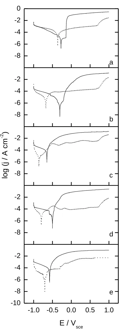
Figure 1. Potentiodynamic polarization curves for (solid) bare and (dotted) ion-nitrided steel specimens after immersion in 0.5 M NaCl. (a) Steel #1, (b) steel #2, (c) steel #3, (d) steel #4, and (e) steel #5.
[image:5.596.197.394.81.629.2]
substrate, indicates that coated specimens always exhibit higher corrosion resistance than the bare steels, over a wide potential range. At potentials more positive than +0.70 Vsce, we observe an increase in the anodic current for the coated steels towards the values typical for the bare steels. This is due to the onset of the oxygen evolution reaction. The polarization response for all five substrates initially shows the cathodic evolution of hydrogen at potentials negative to the corrosion potential. From the corrosion potential upwards, the current densities increase continuously with the applied potentials for steels #2 to #5. These materials suffer severe general corrosion attack. On the other hand, steel #1, owing to the formation of the oxide film, exhibits a low current density up to ca. -0.15 Vsce, when it starts to increase abruptly. The occurrence of localized corrosion is observed.
The polarisation response of ion-nitrided steels, from -1.00 to ca. +0.70 Vsce, features several sequential reactions, including a cathodic evolution of hydrogen, a corrosion resistance enhanced region due to the coating, and a mild dissolution of the surface film. No clear anodic dissolution of the coating immediately following the evolution of hydrogen is observed, and the dissolution of the nitrogen-containing film in the protected range is smaller than that of the uncoated steels. Nevertheless, dissolution cannot be neglected for any of the specimens, as values above 60 µA cm-2 are measured in all cases.
A marked difference exists in the corrosion behaviour of the coated specimens deposited on the substrates as compared with that of the bare materials. The presence of the nitride coating generally causes a shift of the corrosion potential to more negative values and a decrease in the anodic current density by several orders of magnitude, this effect being less pronounced for coated steels #3 and #5. At a certain potential the current density starts increasing quite rapidly due to localized corrosion. In the case of steel #1 (see Figure 1a), both uncoated and ion-nitrided specimens are susceptible to localized breakdown. The presence of the coating, however, drastically shifts the onset of pitting to more positive potentials.
3.2. A.C. electrochemical studies
101 103 105 0 20 40 60 101 103 105 0 20 40 60 101 103 105 0 20 40 60 0 20 40 60 101 103 105
10-3 10-1 101 103 105 101 103 105 0 20 40 60 d c IZ I / / d e g re e s b a e
[image:7.596.181.413.83.611.2]log (f / Hz)
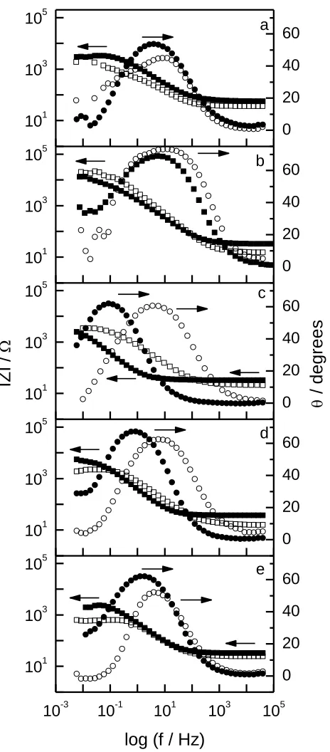
Figure 2. Bode (magnitude Z, phase angle , frequency) plots for EIS spectra of (hollow) bare and (solid) ion-nitrided steel specimens after immersion in 0.5 M NaCl. (a) Steel #1, (b) steel #2, (c) steel #3, (d) steel #4, and (e) steel #5.
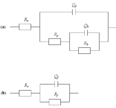
Figure 3. Equivalent circuits for: (a) the ion-nitrided steels, and (b) the uncoated steels.
The equivalent circuit consists of the following elements: a solution resistance Re of the test
electrolyte, electrical leads, etc., the capacitance Qp of the intact (non-defective) coating layer, the
charge transfer resistance associated with the penetration of the electrolyte through the pores or pinholes existing in the coating Rp, and the polarization resistance of the substrate Rb as well as the
electrical double-layer capacitance at the substrate/electrolyte interface Qb.
The capacitances were represented by a constant phase element Q, which accounts for deviations from ideal dielectric behaviour related to surface inhomogeneities [37] or current leakage in the interface. This element is written in its admittance form as
Y*() = Y0 (j)n
where Y0 is the adjustable parameter used in the non-linear least squares fitting, and n is defined
10-3 10-1 101 103 105 101 103 105 0 20 40 60 101 103 105 0 20 40 60 101 103 105 0 20 40 60 101 103 105 0 20 40 60 0 20 40 60 101 103 105
log (f / Hz)
e d c IZ I / / d e g re e s b a
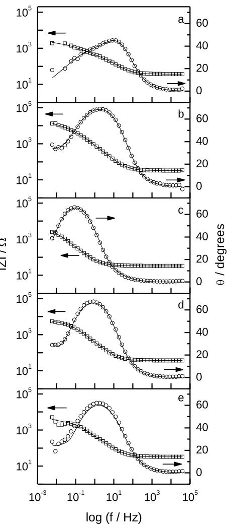
Figure 4. Measured (discrete points) and fitted (solid line) impedance spectra for ion-nitrided steel specimens immersed in 0.5 M NaCl. (a) Steel #1, (b) steel #2, (c) steel #3, (d) steel #4, and (e) steel #5.
[image:9.596.181.407.83.607.2]
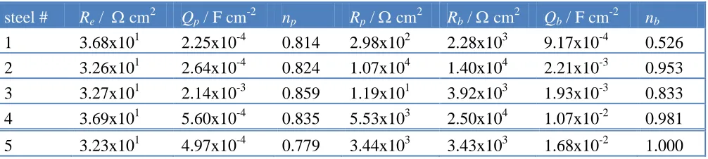
Table 4. Electrochemical parameters obtained with equivalent circuit fitting for ion-nitrided steels in 0.5 M NaCl.
steel # Re / cm2 Qp / F cm-2 np Rp / cm2 Rb / cm2 Qb / F cm-2 nb
1 3.68x101 2.25x10⁻⁴ 0.814 2.98x10² 2.28x10³ 9.17x10⁻⁴ 0.526 2 3.26x101 2.64x10⁻⁴ 0.824 1.07x10⁴ 1.40x10⁴ 2.21x10⁻³ 0.953 3 3.27x101 2.14x10⁻³ 0.859 1.19x101 3.92x10³ 1.93x10⁻³ 0.833 4 3.69x101 5.60x10⁻⁴ 0.835 5.53x10³ 2.50x10⁴ 1.07x10⁻² 0.981 5 3.23x101 4.97x10⁻⁴ 0.779 3.44x10³ 3.43x10³ 1.68x10⁻² 1.000
The important factor from a corrosion perspective is the charge transfer resistance which controls the rate of oxidation at the different anodic interfaces. Therefore, for the sake of comparison with the results achieved for the coated specimens, impedance analysis was also performed on the spectra measured for the bare specimens. In this case, another physical model has to be considered. The Nyquist plots (not shown in the figures) are almost semicircular, indicating that the bare specimens display an activation-controlled behaviour in this electrochemical system. A second arc which is always inductive is also observed at the lowest frequencies, and is related to metal dissolution [39]. In this case, the metallic materials spontaneously undergo active dissolution in the test electrolyte, that is, the iron component in each material is corroding. As the points at the lowest points obviously deviate from the high frequency semicircle representing the activation-control of the system, they were not considered in the analysis. As only one maximum of time constant is observed, the simple equivalent circuit depicted in Figure 3b could be employed, which is frequently used to explain the corrosion behaviour of metallic materials that suffer general corrosion.
In this case, a parallel combination of a charge transfer resistance Rf and a double layer
capacitance Qf is considered in addition to the electrolyte resistance Re. The fits are shown in Figure 5,
and the values of the estimated parameters are given in Table 5. For uncoated steels, the charge transfer resistance Rp was approximately 103 cm2 or lower, a result expected from the active
corrosion behaviour of all samples. A value in the order of 104 cm2 was only found for steel #2, which further confirms this alloy as being the one bearing the highest corrosion resistance in the test environment, whereas steel #3 suffered very severe corrosion. These values confirm the trends already obtained from DC electrochemical experiments.
Table 5. Electrochemical parameters obtained with equivalent circuit fitting for bare steels in 0.5 M NaCl.
steel # Re / cm2 Qf / F cm-2 nf Rf / cm2
[image:10.596.108.485.671.751.2]
10-3 10-1 101 103 105 101 103 105 0 20 40 60 101 103 105 0 20 40 60 101 103 105 0 20 40 60 101 103 105 0 20 40 60 101 103 105 0 20 40 60
log (f / Hz)
e d c IZ I / / d e g re e s b a
Figure 5. Measured (discrete points) and fitted (solid line) impedance spectra for uncoated steel specimens immersed in 0.5 M NaCl. (a) Steel #1, (b) steel #2, (c) steel #3, (d) steel #4, and (e) steel #5.
The ion-nitrided coating did generally increase the charge transfer resistance Rpo, though three
[image:11.596.199.425.86.609.2]
inclusions, the benefit of the ion-nitriding process might arise from homogeneizing or passivating harmful inclusions in the alloy, though such observation should be the object of a more detailed investigation. Thirdly, the highest values are obtained for steels #2 and #4, which have the highest chromium contents. In this way, a strong effect of the substrate nature on the effectiveness of ion-nitride coatings towards the enhancement of corrosion resistance is found in our study. Localized corrosion is the mechanism of corrosion for all coated samples.
It is also interesting to consider the values of the values obtained for Rb, the charge transfer at
the substrate/electrolyte interface. In all cases the values obtained for the coated steels closely match the values observed for a bare surface, strongly supporting that corrosion at pinholes occurs as the result of the metal being directly exposed to the aggressive attack of the electrolyte. In this way we can see that no enhancement of passivity has been achieved through the coating process. Enhanced corrosion resistance is only achieved by the coating acting as a barrier for the diffusion of the aggressive species to the substrate surface. Pores and pinholes in the coating act as paths for the electrolyte attack to the metal beneath, and coating procedures should be further optimized in order to minimize the existence of micro-defects in the coatings.
Finally, these results may be regarded as to get some hints about the origin of the observed shift of Ecor towards less noble values for the coated specimens upon immersion in the test electrolyte. EIS
results give the experimental evidence that coatings are not very dense and present defects, thus the electrolyte advancing towards the substrate should result in the system becoming less noble upon immersion in the aqueous solution.
4. CONCLUSIONS
1. The electrochemical experiments proved to be a good test for studying the resistance and compactness of the coatings. As the coatings are nobler than the underlying substrate, if they are porous, local defects can provide a direct path between the corrosive environment and the substrate. In this way, even at the free corrosion potential Ecor, oxidative dissolution of the substrate in the pores
will result in very high anodic current densities in the pores that match the cathodic reduction of oxygen over the whole surface. Electrochemical techniques can be employed to detect the presence of pores and pinholes in the coating.
2. In general, the ion-nitrided coatings deposited on five different tool steels show corrosion behaviour consistent with enhanced resistance.
3. For uncoated #2 - #5 substrates, a change in the corrosion behaviour from uniform to localized corrosion in the presence of the nitrided coating occurs in 0.5 M NaCl. This localized corrosion is a consequence of the micro-defects present in the coating, as its onset is a function of the underlying substrate.
5. Over the frequency range employed, the equivalent circuit employed for the description of the coated samples provides the best fitting of the experimental data. Charge transfer values obtained from this provide a quantitative basis for corrosion of substrates covered by a ceramic film. Corrosion was observed in all cases, though coated steels #2 and #4 showed the highest corrosion resistance in 0.5 M NaCl.
ACKNOWLEDGMENT
Financial support by the Ministerio de Ciencia e Innovación (MICINN, Madrid, Spain) and the European Regional Development Fund (Brussels, Belgium) under Grant Number CTQ2012-36787 is gratefully acknowledged.
References
1. N.E.W. Hartley, Wear 34 (1975) 427.
2. J. K. Hirvonen, C. A. Carosella, R. A. Kant, I. Singer, R. Vardiman, B. B. Rath, Thin Solid Films 63 (1979) 5.
3. D.-C. Wen, Surf. Coat. Technol. 204 (2009) 511.
4. C. Nouveau, P. Steyer, K.R.M. Rao, D. Lagadrillere, Surf. Coat. Technol. 205 (2011) 4514. 5. L.F. Zagonel, J. Bettini, R.L.O. Basso, P. Paredez, H. Pinto, C.M. Lepienski, F. Alvarez, Surf.
Coat. Technol. 207 (2012) 72.
6. W. Ensinger and G.K. Wolf, Mater. Sci. Eng. A 116 (1989) 1. 7. G.K. Wolf, Surf. Coat. Technol. 83 (1996) 1.
8. A. Medina-Flores, C. Arganis, P. Santiago, J. Oseguera, Surf. Coat. Technol. 188–189 (2004) 140. 9. M.K. Lei, X.M. Zhu, Surf. Coat. Technol. 201 (2007) 6865.
10. L. Nosei, S. Farina, M. Ávalos, L. Náchez, B.J. Gómez, J. Feugeas, Thin Solid Films 516 (2008) 1044.
11. F.Z. Bouanis, F. Bentiss, M. Traisnel, C. Jama, Electrochim. Acta 54 (2009) 2371. 12. Y. Xi, D. Liu, D. Han, Appl. Surf. Sci. 254 (2008) 5953.
13. N. Yasavol, F. Mahboubi, Mater. Design 38 (2012) 59.
14. V. Hrubý, J. Tulka, J. Holík, in: Progress in the Understanding and Prevention of Corrosion, Vol. 1, (J.M. Costa, A.D. Mercer, Eds.). The Institute of Materials, London (1993), p. 195.
15. M.E. Chabica, D.L. Williamson, R. Wei, P.J. Wilbur, Surf. Coat. Technol. 51 (1992) 24. 16. T. Wierzchon, I. Ulbin-Pokorska, K. Sikorski, J. Trojanowski, Vacuum 53 (1993) 473. 17. P.P. Smith, R.A. Buchanan, J.R. Roth, S.G. Kamath, J. Vac. Sci. Technol. B 12 (1994) 940. 18. Y. Li, L. Wang, D. Zhang, L. Shen, J. Alloys Comp. 497 (2010) 285.
19. F.Z. Bouanis, C. Jama, M. Traisnel, F. Bentiss, Corros. Sci. 52 (2010) 3180.
20. M. Ebrahimi, M.H. Sohi, A.H. Raouf, F. Mahboubi, Surf. Coat. Technol. 205 (2010) S261. 21. J.M. Williams, L. Riester, R. Pandey, A.W. Eberhardt, Surf. Coat. Technol. 88 (1996) 132. 22. E. Leitão, R.A. Silva, M.A. Barbosa, Corros. Sci. 39 (1997) 333.
23. R.L.O. Basso, H.O. Pastore, V. Schmidt, I.J.R. Baumvol, S.A.C. Abarca, F.S. de Souza, A. Spinelli, C.A. Figueroa, C. Giacomelli, Corros. Sci. 52 (2010) 3133.
24. E.J. Miola, S.D. de Souza, M. Olzon-Dionysio, D. Spinelli, C.A. dos Santos, Surf. Coat. Technol. 116-119 (1999) 347.
25. F. Borgioli, E. Galvanetto, A. Fossati, T. Bacci, Surf. Coat. Technol. 162 (2002) 61. 26. Y. Li, L. Wang, D. Zhang, L. Shen, Appl. Surf. Sci. 256 (2010) 4149.
29. B.A. Boukamp, Equivalent Circuit, Users Manual, 2nd ed.. University of Twente, Twente (The Netherlands) (1989).
30. P.L. Bonora, G. Cerisola, L. Fedrizzi, C. Tosello, Mater. Sci. Eng. 69 (1985) 283.
31. M. Herranen, U. Wiklund, J.-O. Carlsson, S. Hogmark, Surf. Coat. Technol. 99 (1998) 191. 32. R.M. Souto, H. Alanyali, Corros. Sci. 42 (2000) 2201.
33. A.J. Bard, L. Faulkner, Electrochemical Methods, 2nd ed.. John Wiley, New York (2001), p. 368. 34. F. Mansfeld, M.W. Kendig, S. Tsai, Corrosion 38 (1982) 478.
35. F. Mansfeld, M.W. Kendig, Werkst. Korros. 36 (1985) 473. 36. I. Thompson, D. Campbell, Corros. Sci. 36 (1994) 187.
37. J.A. Bardwell, M.C.H. McKubre, Electrochim. Acta 36 (1991) 647. 38. B.A. Boukamp, Solid State Ionics 18 (1986) 136.
39. M. Keddam, O.R. Mattos, H. Takenouti, Electrochim. Acta 31 (1986) 1147.