UNIVERSITI TEKNIKAL MALAYSIA MELAKA
THE DEVELOPMENT OF SEMIAUTOMATIC VERTICAL
LADDER FOR DOMESTIC APPLICATION
This report submitted in accordance with requirement of the Universiti Teknikal Malaysia Melaka (UTeM) for the Bachelor Degree of Electrical Engineering
Technology (Industrial Power) (Hons.)
by
MUHAMMAD SYAHMI BIN AHMAD KHAIRI B071410137
921005-14-5329
FACULTY OF ELECTRICAL ENGINEERING TECHNOLOGY
i
DECLARATION
I hereby, declared this report entitled “ THE DEVELOPMENT OF
SEMIAUTOMATIC VERTICAL LADDER FOR DOMESTIC APPLICATION ” is the results of my own research except as cited in references.
Signature :………....
Author’s Name :MUHAMMAD SYAHMI BIN AHMAD KHAIRI
ii
APPROVAL
This report is submitted to the Faculty of Electrical Engineering Technology of UTeM as a partial fulfilment of the requirements for the degree of Bachelor of Electrical Engineering Technology (Industrial Power) with Honours. The member of the supervisory is as follow:
iii
ABSTRACT
iv
DEDICATION
Firstly, I want to thanks Allah S.W.T, my beloved mom, dad, family, and my friends at Universiti Teknikal Malaysia Melaka, as well as my close relatives who always
give full support and encouragement.
I would like to express my deepest gratitude to my Bachelor Degree Project Supervisor, Mr. Mohd Firdaus bin Ab Halim who always guides me to achieve and
v
TABLE OF CONTENT
Declaration i
Approval ii
Abstract iii
Dedication iv
Table of content v
List of Tables viii
List of Figures ix
CHAPTER 1: INTRODUCTION
1.1 Project background 1
1.2 Problem statement 2
1.3 Objectives 2
1.4 Scope 3
CHAPTER 2: LITERATURE REVIEW
2.1 Overview 4
2.2 Trolley system 4
2.3 Pulley system 5
2.3.1 Type of pulley system 6
2.3.2 Working process of pulley 7
2.3.3 Advantages of pulley system 7
vi
2.5 Electric motor 9
2.5.1 DC Motor 9
2.5.2 AC Motor 10
2.6 Selection motor in vertical ladder 11
2.6.1 DC series motor 12
2.6.2 DC Shunt motor 13
2.6.3 DC compound motor 13
CHAPTER 3: METHODOLOGY
3.1 Introduction 15
3.2 Literature review 15
3.3 Problem identification 16
3.4 Project design 16
3.5 Development of the hardware 16
3.6 Development of the lab testing 17
3.7 Field testing 17
3.8 Data gathering and reliability 17
3.9 Discussion and conclusion 18
3.10 Flow chart 18
3.11 Progress of project 20
3.12 Designing the project 22
3.12.1 Livewire 22
3.13 Hardware development 24
3.13.1 12V DC Power window Motor 25
3.13.2 Rechargeable battery 12V 9A 25
vii
3.13.4 Pulley bearing 26
3.13.5 Push button 27
3.13.6 Limit switch 27
3.14 Construction of the circuit 27
3.15 Operated the hardware 29
CHAPTER 4: RESULT AND DISCUSSION
4.1 Introduction 31
4.2 Analysis result 31
4.3 Discussion 37
CHAPTER 5: CONCLUSION AND FUTURE WORK
5.1 Introduction 38
5.2 Future work 39
REFERENCE 41
viii
LIST OF TABLE
3.11 (A) Gantt chart for Final Year Project 1 20
3.11 (B) Gantt chart for Final Year Project 2 21
3.13 The selective materials and the price to develop the prototype 24
ix
LIST OF FIGURE
2.2 The example of existing trolley 5
2.3.1 The difference of 3 pulley system 6
2.3.2 Pulley working process 7
2.4 Stability of the forklift 8
2.5 Electric motor 9
2.5.1 Principle operation of DC motor 10
2.5.2 Principle operation of AC motor 11
2.6.1 Circuit DC series motor 12
2.6.2 Circuit DC shunt motor 13
2.6.3 Circuit DC compound motor (long shunt and short shunt) 14
3.10 Flow chart of the project development 19
3.12.1 (A) The Livewire software for designing project 22
3.12.1 (B) Holding motor circuit 23
3.12.1 (C) Expected design of the project 24
3.13.1 12V DC power window motor 25
3.13.2 Battery 12V 9A 25
3.13.3 12 VDC relay 26
3.13.4 Pulley bearing 26
3.13.5 Push button 27
3.13.6 Limit switch 27
3.14 (A) The complete soldered circuit at strip board 28 3.14 (B) The complete soldered circuit at power window motor 28 3.14 (C) The plastic casing with the complete circuit 29
x
3.15 (B) Tachometer 30
3.15 (C) Multimeter 30
4.2 The load (brick) into the base 31
4.2 (A) Graph speed against voltage when moving up with no load 32 4.2 (B) Graph speed against voltage when moving down with no load 32 4.2 (C) Graph speed against voltage when moving up with 5kg load 33 4.2 (D) Graph speed against voltage when moving down with 5kg load 33 4.2 (E) Graph speed against voltage when moving up with 10kg load 34 4.2 (F) Graph speed against voltage when moving down with 10kg load 34 4.2 (G) Graph speed against voltage when moving up with 15kg load 35 4.2 (H) Graph speed against voltage when moving down with 15kg load 35
1
CHAPTER 1
INTRODUCTION
1.1 Project Background
A ladder is a inclined set of rungs or vertical or steps. There are two types of ladder. Rope ladders that are hung from the top and rigid ladders can be leaned at a vertical surface such as a wall . In industry application, a ladder concept like forklift were used to perform the task. The forklift were used to carry up and move the load to another place. Unfortunately, there is no tools and machine that is small scale to simplify and minimize hazard at our home. Therefore, the development of semiautomatic vertical ladder controller for domestic application were the preferred solution. This product were operate by 12V DC power window motor with controlled by relay switch that moves the base up or down and limit switch to stop the operation at the certain point.
2 1.2 Problem Statement
The proposed semiautomatic vertical ladder nowadays is very helpful and useful comparing using the normal ladder. Nowadays, these presently available ladder require the user to carry it manually and that may cause the risk of muscular skeletal disorder (MSD). In industry application, the worker usually uses forklift to perform the task of lifting.Forklift is not practical to use in small area. Unfortunately there is no tools and machine that is small scale to simplify and minimize hazard at our home. In this project, a battery powered vertical ladder for domestic usage is design and developed. This product can lift a load as heavy as 20 kg up to 1 meter height. It is equipped with 12V battery and wheel for portability and user friendly. The ladder is controlled by relay switch that moves the base up or down and limit switch to stop the operation at the certain point. This product also reduce the risk of safety by avoiding the risk of dropping the item to the floor and injure our feet.
1.3 Objectives
The objective of this project are:
1) To design an semiautomatic vertical ladder powered by battery that is safe, reliable, portable, low cost and able to carry up load 20 kg in a height of 1 meter.
2) To develop a vertical ladder that is powered by rechargeable battery and semiautomated with using a switching system.
3 1.4 Scope
The main objective of this project is to developed semiautomatic ladder that using DC power window motor and will be semiautomated by using switching system. The project model can only accommodate 20kg of load. The developed on this project is only work by using battery to operate and make this project portable.
4
CHAPTER 2
LITERATURE REVIEW
2.1 Overview
In this chapter, the current and previous technology will be discussed in order to accomplish the objective of the project. By refering the flow of this project, are comprised the hardware parts and the operation of this project will be carried out in this chapter. More information from the similar project works also has been analysed for this chapter. Thus, this chapter will provide the overall information about the project.
2.2 Trolley system
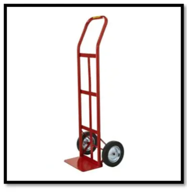
5 surfaces, is called stair climbing trolley. Figure 2.1 show the example of existing trolly that are used by the user.
Figure 2.2: The example of existing trolley
https://www.bunnings.com.au/our-range/garden/garden-hand-tools/trolleys
2.3 Pulley System
6 2.3.1 Type of Pulley system
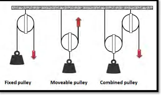
Basically, there are 3 type of pulley which is fixed pulley, movable pulley and combine pulley. All the process operation of the pulley are not same. A fixed pulley is the only pulley that when used single, used more effort that the load to lift the load from the ground. The fixed pulley when attached to an unmovable object, acts as a first class lever with the fulcrum being located at the axis but with a mirnor change, the bar become a rope. The advantages of this pulley pulley is do not have to push or pull the pulley up and down and the disadvantage is it have to apply more effort than the load.
Next, the movable pulley is a pulley that move with the load. The movable pulley allows the effort to be less than the weight of the load. The movable pulley also acts as a second class lever. The load is between the fulcrum and the effort. The advantage of this pulley is used less effort to pull the load and the disadvantage of a movable pulley is have to push or pull the pulley up or down.
[image:17.595.190.449.539.692.2]Finally, the combine pulley makes the life easier as the effort needed to lift the load is less than half the weight of the load. The advantage of the combine pulley is that the amount of effort is less than half of the load and the disadvantage is it travels a very long distance.The combine pulley were selected in this project because it have the all criteria to carry 20kg of the load. Figure 2.2 show the difference of 3 pulley system.
7 2.3.2 Working Process of Pulley
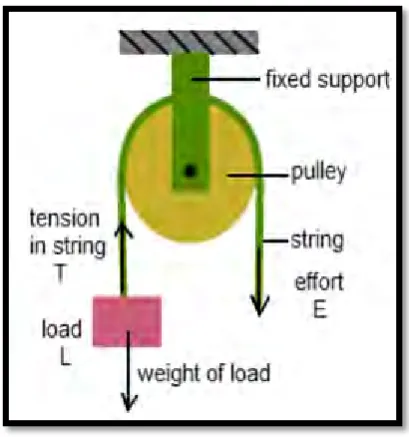
[image:18.595.232.437.193.412.2]A pulley is a rope wrapped around a wheel. It changes the direction of force. A basic compound pulley has a rope attached to a stationary point looped around one wheel and then around a second wheel. Pulling on the rope pulls the two wheels closer together.
Figure 2.3.2: Pulley working process http://physics.tutorvista.com/forces/pulley.html
2.3.3 Advantages of Pulley System
8 2.4 Focklift system
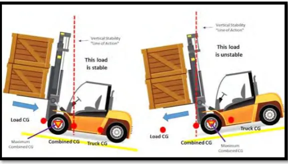
A forklift is a powered industrial truck that used to lift up or down load and move the materials in a short distances. Basically, the stability concept in a focklift system are important to carry a heavy load.In the design of equipment and vehicles it is common to use safety factors to ensure that dynamic effects and wear do not compromise the safety of structures in use. Building crane structures typically have a safety factor of around 6. That is they are designed to withstand 6 times the rated lifting load and chains and slings have a safety factor of around 4. Heavy trucks have safety factors of 3.5 - 5.0 in relation to vertical loads, and trailers a safety factor of 2.5. Chains and webbing used to restrain loads on trucks have safety factors around 2.0.
[image:19.595.173.461.442.606.2]Engineering safety principles in relation to the stability of counterbalance forklifts trucks are expressed in the testing regime prescribed by the ISO Standards, which is related to the risks of tip-overs, roll-overs, and loss of loads [3]. Figures 2.3 show the stability of the focklift to carry up the load.
9 2.5 Electric Motor
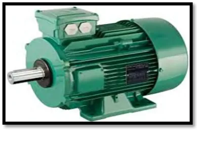
[image:20.595.219.414.245.386.2]An electric motor is an electrical machine that converts electrical energy into mechanical energy. The reverse of electric motor would be the conversion of mechanical energy into electrical energy and is done by an electric generator. Most of electric motor operate through the interaction between an electric motor magnetic field and winding currents to generate force within the motor
Figure 2.5: Electric motor
http://algoelectric.ca/repair-services/electric-motor-rewinding-and-overhauls/
2.5.1 DC Motor
DC motors is a machine that convert d.c power into mechanical power. The working principle of DC motors can be apply by using flemming left hand rule. Rotational speed can easily be controlled by varying the supply voltage. The rotating part of a DC motor is called the armature, and consists of windings similar to those in a wound rotor induction motor. Stator introduces a magnetic field by either permanent magnets or field windings which act on the armature. Current flows through the armature windings via carbon brushes and a commutator assembly. The commutator assembly is easily recognizable as a ring of parallel diametrically opposite pairs of rectangular shaped copper contacts at one end of the armature.
10 connected to a coil winding on the armature, and flows out the other carbon brush via a diametrically opposite commutator contact. This causes the armature to appear as a magnet with which the stator field interacts. The armature field will attempt to align itself with the stator field. When this occurs, torque is produced and the armature will move slightly. At this time, connection with the first pair of commutator contacts is broken and the next pair lines up with the carbon brushes. This process repeats and the motor continues to turn.
[image:21.595.192.444.349.515.2]In automotive industry, they are widely using low power permanent magnet dc motor. Dc motor are also widely used in industrial system, such as robotic manipulators, because their control is relatively simple and they are reliable for a wide range of operation [4].
Figure 2.5.1: Principle operation of DC motor
https://www.electrical4u.com/working-or-operating-principle-of-dc-motor/
2.5.2 AC Motor
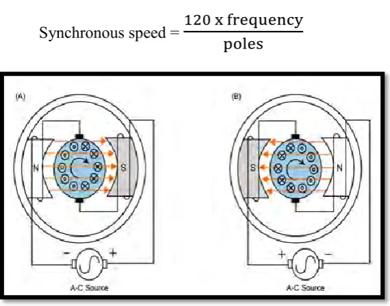
11 the rotor. Each coil is connected to one phase of a three phase power supply. The current through each coil varies sinusoidal with time that out of phase with the other coils. This means that the current in coil is delayed and the current in coil delayed. The rotor sees the net rotating magnetic field created by the three coils and rotates, creating the torque on the motor drive shaft. This field rotates either clockwise or counter clockwise, depending on the order of the phases connected to the motor. The rotating field speed depends on the number of magnetic poles in the stator and is referred to as the synchronous speed. The frequency refers to the power supply frequency. The number of magnetic poles is the principal design factor affecting speed in AC motors.
[image:22.595.193.478.311.534.2]Synchronous speed =
Figure 2.5.2: Principle operation of AC motor
http://www.johnsonelectric.com/en/resources-for-engineers/ac-motors/principle-of-operation
2.6 Selection of motor in vertical ladder
12 2.6.1 DC series motor
DC series motor basically used for high starting torque application and has a greatest torque compare to other motors. DC series motor is a type that the speed is automatic varies commonly with loads by increase and decrease the loads. The motor is used to limit the case where the heavy power demand and necessary to speed up the machine. This motor are should never to be used wheres the motor are cabbing with no loads since it will race with dangerous degree. This motor include crane hoist where the heavy loads will be lifted up and down. It also provide the starting required torque for moving any loads which is heavy.
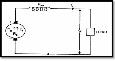
[image:23.595.243.464.454.572.2]A DC motor, whose field winding is excited by the current produced by itself, is called self-excited. In DC series motor the field windings are connected to the armature in series so that whole current flows through the field windings as well as load. Since series field winding carries a full load current, series field is designed with less turns of thick wire or strips. The resistance of series field is kept very low. Therefore Ia=Ise=IL [5]. Figure 2.8 show the circuit of DC series motor.
Figure 2.6.1: Circuit DC series motor
13 2.6.2 DC shunt motor
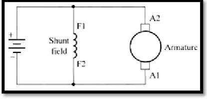
[image:24.595.249.457.311.410.2]In shunt motor, the field circuit is connected in parallel with the armature circuit. DC shunt motor are widely used because it have a linear characteristic of torque and voltage, it also has suitable control speed over various load and it is constant. DC shunt motor run with constant speed to the load. DC shunt motor are not usually servers and recommended while doing testing condition. The speed may operated in two ways which is by inserting resistance in series with armature thus it will decrease the speed. By inserting a resistance in field circuit, the speed of motor will vary with a changing loads and the speed are constantly for any setting of the controller.
Figure 2.6.2 : Circuit DC shunt motor
http://www.ddmotorsystems.com/CurrentRange.php
2.6.3 DC compound motor