ScienceDirect
Available online at www.sciencedirect.com
Procedia Engineering 207 (2017) 1433–1438
1877-7058 © 2017 The Authors. Published by Elsevier Ltd.
Peer-review under responsibility of the scientific committee of the International Conference on the Technology of Plasticity. 10.1016/j.proeng.2017.10.909
10.1016/j.proeng.2017.10.909
© 2017 The Authors. Published by Elsevier Ltd.
Peer-review under responsibility of the scientific committee of the International Conference on the Technology of Plasticity.
1877-7058
ScienceDirect
Procedia Engineering 00 (2017) 000–000
www.elsevier.com/locate/procedia
1877-7058 © 2017 The Authors. Published by Elsevier Ltd.
Peer-review under responsibility of
the scientific committee of the International Conference on the Technology of
Plasticity
.International Conference on the Technology of Plasticity, ICTP 2017, 17-22 September 2017,
Cambridge, United Kingdom
New method of producing tailored blanks with constant thickness
Andrzej Rosochowski
a*, Lech Olejnik
baDesign, Manufacture and Engineering Management, University of Strathclyde, 75 Montrose Street, Glasgow G1 1XJ, United Kingdom bInstitute of Manufacturing Processes, Warsaw University of Technology, 85 Narbutta Street, Warsaw 02-524, Poland
Abstract
The concept of weight-saving in automotive manufacture by using tailored blanks is well established. The methods used to produce extra strength in particular areas of the blank can be based either on increasing material thickness in those areas or keeping the thickness constant but varying the material properties. Typically the first option is used by welding blank patches of different thickness. From the view point of forming blanks into sheet metal products uniform thickness is less problematic and it can be achieved by welding different materials of the same thickness or localised heat treatment. However, these approaches have major limitations: welding introduces discontinuity in material structure and properties while selective heat treatment is difficult to control. A new, original method presented here is based on a local shear deformation of the blank material. The particular process used is incremental equal channel angular pressing. The proposed approach is simulated using finite element modelling and then experimentally verified by producing a constant thickness pure aluminium strip with varying hardness. A discussion of different variants of this approach indicates its potential.
© 2017 The Authors. Published by Elsevier Ltd.
Peer-review under responsibility of
the scientific committee of the International Conference on the Technology
of Plasticity
.Keywords: Tailored blanks; sheet metal; incremental forming; shear deformation
* Corresponding author. Tel.: +44 141 5484353.
E-mail address: [email protected]
ScienceDirect
Procedia Engineering 00 (2017) 000–000
www.elsevier.com/locate/procedia
1877-7058 © 2017 The Authors. Published by Elsevier Ltd.
Peer-review under responsibility of
the scientific committee of the International Conference on the Technology of
Plasticity
.International Conference on the Technology of Plasticity, ICTP 2017, 17-22 September 2017,
Cambridge, United Kingdom
New method of producing tailored blanks with constant thickness
Andrzej Rosochowski
a*, Lech Olejnik
baDesign, Manufacture and Engineering Management, University of Strathclyde, 75 Montrose Street, Glasgow G1 1XJ, United Kingdom bInstitute of Manufacturing Processes, Warsaw University of Technology, 85 Narbutta Street, Warsaw 02-524, Poland
Abstract
The concept of weight-saving in automotive manufacture by using tailored blanks is well established. The methods used to produce extra strength in particular areas of the blank can be based either on increasing material thickness in those areas or keeping the thickness constant but varying the material properties. Typically the first option is used by welding blank patches of different thickness. From the view point of forming blanks into sheet metal products uniform thickness is less problematic and it can be achieved by welding different materials of the same thickness or localised heat treatment. However, these approaches have major limitations: welding introduces discontinuity in material structure and properties while selective heat treatment is difficult to control. A new, original method presented here is based on a local shear deformation of the blank material. The particular process used is incremental equal channel angular pressing. The proposed approach is simulated using finite element modelling and then experimentally verified by producing a constant thickness pure aluminium strip with varying hardness. A discussion of different variants of this approach indicates its potential.
© 2017 The Authors. Published by Elsevier Ltd.
Peer-review under responsibility of
the scientific committee of the International Conference on the Technology
of Plasticity
.Keywords: Tailored blanks; sheet metal; incremental forming; shear deformation
* Corresponding author. Tel.: +44 141 5484353.
1.Introduction
Tailored blanks are sheet metal blanks with either local variation of thickness or properties [1]. When used for sheet metal formed automotive components, they enable substantial weight and cost savings. The most popular approach to producing tailored blanks is based on differentiation of sheet thickness in otherwise uniform material. This can be achieved by butt welding of sheets with different thickness or lap welding to create patches to create so-called tailored welded blanks (TWB). The welding technology is well established but has a disadvantage of introducing a material discontinuity, which causes problems during sheet metal forming and product exploitation. Also, some metals are not easily weldable. An alternative newer approach is based on flexible rolling, where a roll gap changes programmatically during the process, to produce tailored rolled blanks (TRB) [2]. This approach usually leads to a long thickness transition zone. Tailored blanks with uniform thickness are more attractive from the subsequent forming point of view. They can be produced by welding different materials of the same thickness or local heat treatment of a sheet metal (THTB) to change its properties, mainly to make it softer and more ductile [3]. These methods are still problematic since the former introduces a discontinuity while the latter is difficult to control.
2.New concept
When considering constant thickness tailored blanks, there is a question how can a blank material be made locally stronger without reducing its thickness? A new process invented at University of Strathclyde [4-6], called Incremental Equal Channel Angular Pressing (I-ECAP) offers a solution. It is a severe plastic deformation process [7, 8] addressing the problem of short billets in conventional ECAP [9] by separating and synchronising material feeding and deformation (Fig.1). Shear mode of deformation is caused by a reciprocating punch, which deforms incrementally fed material locally at a turn of a constant cross-section channel. Because of its incremental nature, the process is able to produce long bars, plates and sheets [10] with refined microstructure (so called ultrafine grained metals), improved strength and adequate ductility. It was tested on aluminium, copper, magnesium, iron and titanium, on constant thickness billets processed over their whole length [11].
[image:2.544.86.439.403.558.2]I-ECAP can be used as a means of locally changing sheet metal thickness [12, 13] but in the context of this paper its ability to produce tailored blanks with constant thickness but varying hardness is going to be explored. Since the main mode of deformation during I-ECAP is simple shear, tailored blanks produced by I-ECAP are referred to as tailored sheared blanks (TSB). The idea was first formulated in [14] but has never been proven experimentally. In this paper, FE simulation is used to explain the concept of producing TSBs by I-ECAP and to provide insight into strain distribution. This is followed by the experimental part of the paper comprising I-ECAP of an aluminium strip and hardness measurements along that strip.
Fig. 1. Schematics of conventional ECAP and I–ECAP [8].
3.FE simulation
The Abaqus/Explicit FE model used for process simulation was generally based on the experiment described in section 4. The material was a 2 mm thick, 50 mm wide and 80 mm long (in the experiment the length was 160 mm) annealed commercial purity aluminium strip. It was modelled as an elastic-plastic, isotropic, Huber/Mises material undergoing strain hardening as described by σ=130(0.005+ε)0.3. The mode of deformation was plain strain so the
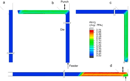
[image:3.544.54.479.294.557.2]width of the strip was kept constant as required in ECAP. Friction was assumed to follow Coulomb’s law with friction coefficient μ=0.1. The punch was reciprocating in the feeding direction, with a high frequency (to shorten calculation time) and amplitude of 0.8 mm. The feeding stroke was 0.2 mm. Fig. 2 presents the equivalent strain results obtained in this simulation. Fig. 2a shows the initial tool/material configuration. In Fig. 2b, the first pass of I-ECAP is interrupted after the 1/3 of the strip's length is processed. This, together with changing the strip orientation between the first and the second pass, shown in Fig. 2c, is the essence of the proposed approach. The strain achieved after one pass is approximately 1.15, as expected for ECAP with the channel angle of 90°. The second pass of the process performed on the same material doubles that strain and straightens the strip (Fig. 2d). The remaining part of the strip is not deformed at all. The transition zone between the deformed and undeformed part of the strip is thin compared to the strip thickness and angled. There is a small undeformed zone at the back of the deformed strip, so-called end effect inherent in ECAP.
Fig. 2. Equivalent strain distribution in TSB produced by I-ECAP: (a) start of the process; (b) after I-ECAP of strip over required distance; (c) after rotation by 180° and reversed feeding; (d) after second pass of I-ECAP over the same region.
a
c
d
Die
Feeder Punch
4.Experiment
The experiment (Fig. 3) was carried out at University of Strathclyde using an experimental rig (similar to one described in [10]) capable of processing two 160x50x2 mm strips at the same time. The strips were fed from the bottom of a servo hydraulic press using a screw jack; the feeding stroke was 0.2 mm. The amplitude of a reciprocating punch driven by the press was 0.8 mm while its frequency was 0.5 Hz. Synchronisation of material deformation and feeding was realised by enabling communication between the press control system (Cubus) and screw jack (LabView). The material used was commercial purity Al1050 annealed at 350°C over 2 hours. Since industrial type conversion coating of aluminium was not available, the strips were prepared by sand blasting, spraying with water suspension of graphite, drying and brushing with an anti-seize heavy duty lubricant.
The first pass of I-ECAP was interrupted at approximately 1/3 of the strip length. The deformed parts were slightly bent (Fig. 3), which was easily rectified before the next pass of the process to help insert the strips into the die. As can be seen in Fig. 4, the strips were nearly identical, with only a small difference of thickness (about 0.05 mm) in the deformed part because of the tool misalignment. Vickers hardness was measured using DuraScan-70 G5 tester. The initial hardness of the material, measured directly on a rolled and annealed strip, was 27.8 HV0.2. The processed part of the strip achieved the average hardness of 44.4 HV0.2 after first pass of I-ECAP.
In the second pass, the strips were reoriented as shown in Fig. 2c, which led to obtaining flat strips with two regions, a shorter one
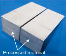
[image:4.544.41.209.101.244.2]processed twice and a longer one not subjected to shear at all (Fig. 5a). The thickness of the flat strips was nearly constant (Fig. 5b), with a slightly reduced thickness of the processed region due to imprecise control of the bottom position of the punch.
Fig. 5. TSBs produced by two passes of I-ECAP: (a) flat strips after 2nd pass; (b) longitudinal edge of the flat strip.
Processed material
a
[image:4.544.363.497.279.394.2]b
Fig. 4. Two angled strips after first pass of I-ECAP.
[image:4.544.130.406.482.637.2]Processed material
Hardness measurements were carried out on three small specimens cut out from different regions of the flat strip produced by two passes of I-ECAP (Fig. 6). Specimen 1 covered the zone subjected entirely to two passes, specimen 2 went across a boundary between two pass region and the unprocessed region and specimen 3 was entirely in the unprocessed region. Hardness of the unprocessed region was 29.3 HV0.2, which was slightly higher than 27.8 HV0.2 for the initial material. The difference resulted from the fact that the nominally unprocessed material in the feeding channel was actually slightly plastically compressed after being inserted there with a clearance. The boundary between the two zones witnessed a jump of hardness to 47.4 HV0.2, which was only 3 HV0.2 more than after the first pass. This small difference was due to reduced material hardening capacity after being processed to strain of 1.15 in the first pass. The thickness of the transition zone was approximately 5 mm for 2 mm thick strip.
Fig. 6. Hardness HV0.2 measurement results after two passes of I-ECAP.
5.Discussion and conclusions
Fig. 7. Different configurations for TSBs produced by two passes of I-ECAP.
0 10 20 30 40 50
0 10 20 30 40 50 60 70 80 90
1 2 3
[image:5.544.222.477.446.643.2]Division of a strip into a weaker and stronger part, discussed so far, is not the only configuration for a TSB, which can be produced by I-ECAP. Fig. 7 presents this configuration (Fig. 7a) and some other configurations of weak and strong zones, which can be achieved with this process. Fig. 7b presents a configuration, which can be produced by continuing working on the other end of a TSB shown in Fig. 7a. Three zones of different hardness can be obtained if the initial strip is bent like shown in Fig. 7c. To obtain a middle strong zone one has to interrupt the 2nd pass from Fig. 7c and straighten the strip (Fig.
7d). Continuation of case above; additional straightening required
Soft material Stronger material (2 passes) Stronger material (1 pass)
Additional initial bending required Continuation of case above Stronger material (2 passes) Soft material
Soft material Stronger material (2 passes) Soft material Stronger material (2 passes) Stronger material (2 passes) Soft material
a
b
c
d
HV0.2
Distance
Initial material
After 1st pass
After 2nd pass specimen 1
5 mm
Ideally, straightening of strips is carried out only by simple shear during second pass of I-ECAP (Fig. 7a, Fig. 7b). Straightening of angled strips after I-ECAP can be a bit problematic because of nearly non-existing corner radius. Compression of strips, with a slight thickness reduction should be able to help with this problem. Equally slight reduction rolling could work. Rolling may be utilised to calibrate and improve surface finish of strips after I-ECAP but can also be used to substantially reduce thickness of thicker strips, which can be processed by I-I-ECAP to improve productivity. The level of strain in different zones of a strip can be controlled by using dies with different angle of the channel (angle larger than 90° produces lower strain). In the laboratory experiment reported here, the as received cold rolled material was annealed to provide a low value and consistent hardness reference. In practice, the cold rolled material is expected to be directly subjected to I-ECAP, which will reduce the hardness difference observed in the experiment. Also post I-ECAP cold rolling is expected to change differently the hardness of strips in different zones. All these aspects should be investigated further to improve our understanding of different process design options for TSBs.
Numerical simulation as well as experimental work has confirmed that the new proposed method of producing constant thickness tailored sheared blanks by incremental ECAP is feasible on a laboratory scale. After two passes, the process generated equivalent strain of 2.3 while keeping the strip thickness constant. For comparison, the same level of strain produced by rolling requires 90% thickness reduction. It is expected that tailored sheared blanks will save more material and therefore further reduce the weight of vehicles made of sheet metal formed parts. At the same time, sheet metal forming operations should become easier compared to using varying thickness blanks especially those most popular ones made by welding.
Acknowledgements
Help of Strathclyde students, Stuart Taylor and Frida Gjertsen, in tool design and carrying out the experiments is gratefully acknowledged.
References
[1] M. Merklein, M. Johannes, M. Lechner, A. Kuppert, A review on tailored blanks - Production, applications and evaluation, J. Mater. Process. Tech. 214 (2014) 151-164.
[2] R. Kopp, C. Wiedner, A. Meyer, Flexibly rolled sheet metal and its use in sheet metal forming, Adv. Mater. Res. 6-8 (2005) 81-92.
[3] M. Merklein, M. Geiger, D. Staud, U. Vogt, Tailored heat treated blanks applied on car body parts under quasi-series conditions. Int. J. Microstructure and Materials Properties 4/5-6 (2009) 525-533.
[4] A. Rosochowski, Severe plastic deformation of metals, European Patent 1861211 (2012) [5] A. Rosochowski, Severe plastic deformation of metals, U.S. Patent 8,631,673 (2014)
[6] A. Rosochowski, L. Olejnik, FEM simulation of incremental shear, in: E. Cueto, F. Chinesta (Eds), Proc. of the 10th International Conference on Material Forming, Esaform 2007, April 18-20, 2007, Zaragoza, Spain, AIP Proceedings 907, 2007, pp. 653-658.
[7] A, Rosochowski, L. Olejnik, Severe plastic deformation for grain refinement and enhancement of properties, in: J. Lin, D. Balint, M. Pietrzyk (Eds.), Microstructure evolution in metal forming processes, Woodhead Publishing Limited, 2012, pp. 114-141.
[8] A. Rosochowski (Ed.), Severe Plastic Deformation Technology, Whittles Publishing, Scotland, 2017.
[9] V.M. Segal, V.A. Reznikov, A.E. Drobyshevskiy, V.I. Kopylov, Plastic working of metals by simple shear,Russ. Metall. 1 (1981) 99-105. [10] A. Rosochowski, M. Rosochowska, L. Olejnik, B. Verlinden, Incremental equal channel angular pressing of sheets, Steel Res. Int. 81/9
(2010) 470-473.
[11] M. Gzyl, A. Rosochowski, N.M. Katimon, S. Boczkal, L. Olejnik, Producing high-strength metals by I-ECAP, Advanced Engineering Materials 18/2 (2016) 219-223
[12] A. Rosochowski, L. Olejnik, M. Rosochowska, Tailored sheared blanks produced by incremental ECAP, Key Eng. Mat. 651-653 (2015) 651-656.
[13] L. Olejnik, A. Rosochowski, Production of tailored blanks by Incremental ECAP, Metal Forming (Obrobka Plastyczna Metali) 26/4 (2015) 307–324.
![Fig. 1. Schematics of conventional ECAP and I–ECAP [8].](https://thumb-us.123doks.com/thumbv2/123dok_us/1486432.101304/2.544.86.439.403.558/fig-schematics-conventional-ecap-and-i-ecap.webp)