City, University of London Institutional Repository
Citation
:
Mirshahi, M., Yan, Y. & Nouri, J. M. (2015). Influence of cavitation on near nozzle exit spray. Journal of Physics: Conference Series,, 656(1), 012093. doi:10.1088/1742-6596/656/1/012093
This is the published version of the paper.
This version of the publication may differ from the final published
version.
Permanent repository link:
http://openaccess.city.ac.uk/14339/Link to published version
:
http://dx.doi.org/10.1088/1742-6596/656/1/012093Copyright and reuse:
City Research Online aims to make research
outputs of City, University of London available to a wider audience.
Copyright and Moral Rights remain with the author(s) and/or copyright
holders. URLs from City Research Online may be freely distributed and
linked to.
City Research Online: http://openaccess.city.ac.uk/ publications@city.ac.uk
This content has been downloaded from IOPscience. Please scroll down to see the full text.
Download details:
IP Address: 138.40.68.78
This content was downloaded on 04/05/2016 at 14:11
Please note that terms and conditions apply.
Influence of cavitation on near nozzle exit spray
View the table of contents for this issue, or go to the journal homepage for more 2015 J. Phys.: Conf. Ser. 656 012093
(http://iopscience.iop.org/1742-6596/656/1/012093)
Influence of cavitation on near nozzle exit spray
M Mirshahi1,2, Y Yan2, JM Nouri2
2 City University London, Northampton Square EC1V 0HB, United Kingdom
Milad.Mirshahi.1@city.ac.uk
Abstract. The importance of cavitation inside multi-hole injectors for direct injection internal combustion (IC) engineshas been addressed in many previous investigations. Still, the effect of cavitation on jet spray, its stability and liquid breakup and atomisation is not yet fully understood. The current experimental work aims to address some of these issues. It focuses on the initiation and development of cavitation inside a 7x enlarged transparent model of a symmetric 6-hole spark ignition direct injection (SIDI) injector and quantifies the effect of cavitation on near-nozzle spray cone angle and stability utilising high speed Mie scattering visualisation. The regions studied include the full length of the nozzle and its exitjet spray wherethe primary breakup takes place.
1. Introduction
Multi-hole injectors for IC engines are wildly used in both diesel and gasoline engines and have many advantageous such as their flexibility in terms of number of holes and their arrangements which can be fitted to different combustion cylinder head, their ability to produce stable spray which is critical for spray guided combustion concept and their ability to be used at high injection pressure to ensure enhanced atomization and evaporation [1, 2]. Experimental studies of in-nozzle flow characteristics, in particular, cavitation in enlarged transparent models of multi-hole injectors and spray characteristics of real size ones have been extensively investigated by City research group [3-10]. These studies revealed the formation of three different types of cavitation, namely needle, geometric and string cavitation.Cavitation within the nozzle holes of multi-hole SIDI injectors can lead to significant spray instabilities and lack of targeting which can cause problems in combustion when operating in stratified mode. The simultaneous presence of these types of cavitation regimes creates a complex two-phase flow structure in the nozzle holes which seems to be responsible for hole-to-hole and cycle-to-cycle spray variations. Investigations [7-10] revealed the cavitation sites, their frequency of formation, and the locations of erosion within the nozzle. In addition, they showed how to minimise surface erosion using tapered converging holes. Large variations in the instantaneous fuel injection quantity of individual injection holes have been recorded when a cavitation string is observed inside them. Combination with model predictions has revealed that the observed reduction in the individual hole flow rate is partially attributed to the increased vapour fraction inside the hole when a string is present; the vortex flow developing upstream of the hole entry is the main reason for the observed trend [9].
Despite available information, the true dynamics and mechanisms of cavitation development and its link with near nozzle liquid break-up at the exit of the nozzle hole are not fully understood. Therefore deeper understanding of in-nozzle flow characteristics and the dynamic link between cavitation and the emerging jet spray is essential. This calls for high temporal simultaneous imaging of the in-nozzle
1 Corresponding author
9th International Symposium on Cavitation (CAV2015) IOP Publishing
Journal of Physics: Conference Series 656 (2015) 012093 doi:10.1088/1742-6596/656/1/012093
Content from this work may be used under the terms of theCreative Commons Attribution 3.0 licence. Any further distribution of this work must maintain attribution to the author(s) and the title of the work, journal citation and DOI.
cavitation and the exiting liquid jet spray in order to establish how cavitation influence spray shape, instability and break up. Thus the focus of this study is to establish these links and their mechanisms in a 7x 3-D transparent models of a six-hole mini-sac-type nozzle utilised with gasoline direct injection; a high speed camera has been used to obtain simultaneous images at a rate of 50,000fps.
2. Experimental test-rig
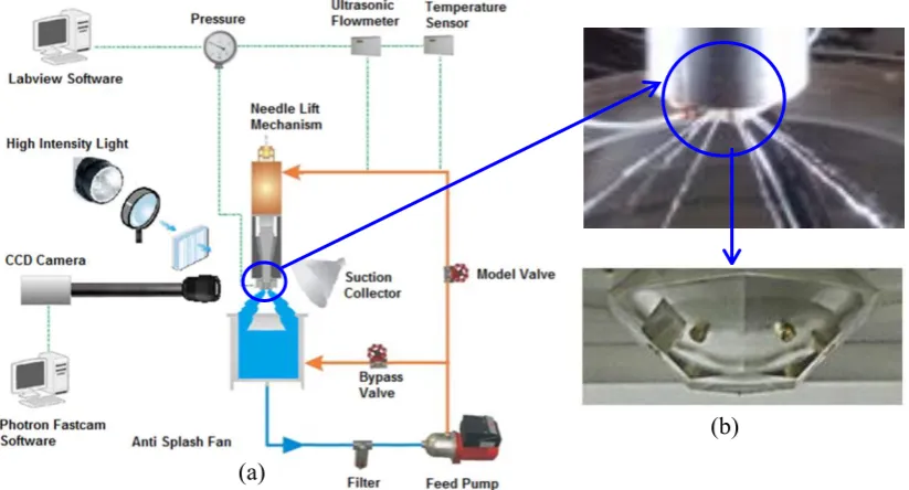
The experimental set up is shown in fig. 1a. A multistage centrifugal pump provides the upstream pressure in the transparent enlarged model. Working fluid is water at 25oC. A long telescopic
[image:4.595.94.506.381.603.2]extension tube was used on the CCD camera to maximise the magnification ratio of the screening area. The injection pressure was varied from 0.5 bar to 3bar and the sprays from each nozzle hole were injected into the atmosphere and were collected back into the supply tank. A 100mm diameter focusing lens with the focal length of 300mm was used to increase the light intensity around the nozzle area to more than 2 million Lux. Three set of 45° hot mirrors were used to filter out infrared wavelength in order to protect the Perspex nozzle from high temperatures. To ensure capturing high quality images, 2 set of cooling fans were used to decrease the temperature further around the nozzle and also to remove the water mists of the spray away from the near nozzle towards the suction collector to avoid fouling the imaging window. The injector assembly has a needle lift mechanism adjusted by a micrometer to set the exact needle height. The flow inside the nozzles is continuous, i.e. steady state flow condition, which means that transient nature of needle during its opening and closing processes is absent. The enlarged transparent model is geometry similar to the real-size injector and operates at similar Reynolds numbers.
Fig. 1.(a) The closed loop steady-state flow rig of the transparent 7 times enlarged injector with the schematic diagram of flow circuit (left); (b) Close-up of transparent nozzle injector assembly.
Fig. 2.Front view of the 7-times enlarged model installed on the test rig (red box) and schematic of the imaging area and the near-nozzle jet(yellow box).
(a)
(b)
9th International Symposium on Cavitation (CAV2015) IOP Publishing
Journal of Physics: Conference Series 656 (2015) 012093 doi:10.1088/1742-6596/656/1/012093
[image:4.595.87.494.652.756.2]3. Results
Sample images of the results are shown below. Fig. 3 shows a sequence of 6 images of the in-nozzle flow and the emerging spray at full lift (1.05mm) at cavitation numbers of CN = 0.75, 1, 1.5, 1.75, 2, and 2.5. Cavitation number is defined here as CN= (Pinj - Pback)/(Pback - Pvap). Cavitation was not present
at CN range between 0.75 to 1.0. Increasing cavitation above 1 induces cavitation in the nozzle and resulted to full film cavitation from CN=2 and above. It can be claimed that as the cavitation number rises from 1.0 to 1.5, the upper near-nozzle spray angle increases due to cavitation as can be seen from the images shown in fig. 3.
Fig. 3. In-nozzle flow and the emerging spray at CN = 0.75, 1, 1.5, 1.75, 2, and 2.5.
Fig. 4. Comparison of the upper and lower part of the very near-nozzle spray at CN=2.
t = 0μs
t = 20μs
t = 40μs t = 100μs
t = 80μs t = 60μs CN = 0.75
CN = 1
CN = 1.5
CN = 1.75
CN = 2
CN = 2.5 1mm
1mm
String cavitation
9th International Symposium on Cavitation (CAV2015) IOP Publishing
Journal of Physics: Conference Series 656 (2015) 012093 doi:10.1088/1742-6596/656/1/012093
As cavitation number gradually increases from 1.5 to 2.0, the geometric cavitation becomes more intense and stretches down the nozzle towards the exit. Another observation is that the structure of the geometric cavitation on top of the nozzle undergoes a transition with increase in CN from a cluster of bubbly cloud vapour into a smoothly horseshoe film cavitation as evident from images at CN=2 and CN=2.5 respectively; this had impact on the structure of the upper part of the near exit spray. Fig. 4 shows a sequence of 6 consecutive images of the in-nozzle flow and the emerging spray at CN = 2.0 during 100μs. The sequence depicts the near-nozzle structure of the spray with the extension of the smooth curved line that is stretched out of the nozzle. At t = 0, a pocket of bubbles was observed at the lower part of the nozzle inlet. This moves down and reaches the nozzle exit at t=100μs. This shows that the average velocity of this pocket is around 20m/s. However the upper part of the spray has much lower velocity (around 7m/s; tracked by the bold yellow circles) compared to the bottom part of the nozzle where the bulk of the liquid exists.
4. Conclusion
Simultaneous imaging of in-nozzle cavitation and emerging spray have been obtained in a 7 times enlarged model of SIDI injector at different injection pressures and needle lifts under steady state conditions. Observations showed that bubble cloud cavitation influence the structure and the angle of emerging spray, in particular, on the upper part of the nozzle which could lead to spray instabilities. It has also been observed that once the geometric cavitation reaches the exit of the nozzle, its structure transform from a bubbly cloud into a smoothly curved lines film cavitation, which greatly influences the exiting spray structure. Further image analysis showed lower spray velocities on the upper part of the nozzle, where the spray is dominated by in-nozzle cavitating flow, than the lower part.
5. References
[1] Fraidl G,et al.2003 The potential of next generation gasoline direct injection technologies. AssociazioneTecnicadell’Automobile, 56: p. 5-17.
[2] Wirth M. et al.2004A Cost Optimised Gasoline Spray Guided Direct Injection System for Improved Fuel Economy, Seminar on Fuel Economy and Engine Downsizing. IMechE symposium, 13 May 2004London.
[3] Nouri J.M., et al.2012Effect of viscosity, temperature and nozzle length-to-diameter ratio on internal flow and cavitation in a multi-hole injector.In Proc. IMechE Seminar on Fuel Injection. 14-15March 2012, London.
[4] Arcoumanis et al, 1998 Analysis of the flow in the nozzle of a vertical multi-hole diesel engine injector. Transactions Journal of Engines, SAE paper 98-08-11.
[5] Soteriou, et al. 1993 Cavitation Hydraulic Flip and Atomization in Direct Injection Diesel Sprays, IMechE 1993. London.
[6] Roth H, et al.2002 Cavitation Initiation, Its Development and Link with Flow Turbulence in Diesel Injector Nozzles. Transactions Journal of Engines, SAE paper 2002-01-0214, SAE Transactions, 111(3): p. 561-580.
[7] Gavaises, M. et al. 2009 Characterization of string cavitation in large-scale Diesel nozzles with tapered holes. Int J Physics of Fluids, 21: p. 052-107.
[8] Gavaises, M., 2007 Link Between Cavitation Development and Erosion Damage in Diesel Injector Nozzles. SAE paper 2007-01-0246.
[9] Andriotis, A., Gavaises, M. & Arcoumanis, C. 2008. Vortex flow and cavitation in diesel injector nozzles. Journal of Fluid Mechanics, 610, pp. 195-215
[10] M Gavaises et al. 2008. Flow in valve covered orifice nozzles with cylindrical and tapered holes and link to cavitation erosionand engine exhaust emissions. International Journal of Engine Research 9: 43-52.
9th International Symposium on Cavitation (CAV2015) IOP Publishing
Journal of Physics: Conference Series 656 (2015) 012093 doi:10.1088/1742-6596/656/1/012093