Sustainable decommissioning of an offshore wind farm
Eva Topham
*, David McMillan
University of Strathclyde, UK
a r t i c l e i n f o
Article history:
Received 24 February 2016 Received in revised form 19 October 2016 Accepted 30 October 2016 Available online 2 November 2016
Keywords: Decommissioning Marine renewable energy Offshore wind energy Offshore wind farms Sustainable
a b s t r a c t
The offshore wind industry has historically focused on setting up new projects, with the decom-missioning phase receiving little attention. This can cause future problems as decomdecom-missioning needs to be planned at the beginning to prevent complications that may arise, as it implies important operations and high costs. There are numerous features that make decommissioning a challenge, such as the marine environment, the technical limitations of vessels and the lack of specific regulations that determine what should be done, increasing the uncertainty of the process. Additionally, the unique characteristics of the sites involve exclusive optimal solutions for each project. This article analyses the main operation pa-rameters that affect the decommissioning process, identifying the benefits and drawbacks of the infl u-encing variables. A model is designed to compare different transportation strategies, searching for cost reduction. A decommissioning methodology is been proposed based on this analysis, taking into consideration the technical aspects of the process, and minimising environmental impacts. The model forecasts that the predicted duration and costs of this process are not being adequately captured in site decommissioning plans.
©2016 The Authors. Published by Elsevier Ltd. This is an open access article under the CC BY license (http://creativecommons.org/licenses/by/4.0/).
1. Introduction
Offshore wind farms are relatively new, and therefore owner/ operators have been mainly concerned with improving installation techniques and achieving operational efficiency. Despite the potentially large costs, logistical difficulties and environmental impacts, decommissioning has been given little attention to date. This is an important matter because decommissioning is a signifi -cant part of any project, and should be considered from the very beginning, from the design stage, as if not done then, impacts can become more severe and costs can be higher than expected.
Decommissioning is the last phase in a project’s lifecycle and can be considered as the opposite of the installation phase [1], where the principle“the polluter pays”applies[2], and ensures that the site is left in a similar condition as it was before the deployment of the project. The first offshore wind energy project to be decommissioned took place in 2016, Yttre Stengrud, a 10 MW project withfive 2 MW turbines which operated for more than a decade[3], significantly less than the expected lifetime of 20e25 years [4]. The decommissioning of the next two offshore wind
farms has also been announced: Lely, a 2 MW project consisting of four 500 kW turbines which have been operating since 1994[5]
and Vindeby, the first offshore wind farm to be installed, a 4.95 MW pilot plant of eleven 450 kW wind turbines with gravity based foundations[6]. The owner/operator decided to decommis-sion the wind farm after 25 years of operation, reaching the pre-dicted number of operating years[7].
An important early observation is that the requirements of a decommissioning scheme are unique to each site, when referred to the operating procedures regarding the site characteristics and the time, the type of structures involved, the equipment used, or the market conditions and contractual terms. On the one hand, this complicates the development of a general methodology that could be applied to any wind farm. On the other hand, the majority of offshore wind farms that will be decommissioned in the next decade will be monopile foundations, in relatively shallow waters (less than 50 m), and with few small sized turbines, which will give the opportunity for decommissioning teams to learn in “easy”
environments.
It is highly likely that, before a complete dismantling of the site, repowering or refurbishment options will be studied by the owner/ operator. Repowering involves the replacement of the existing turbines into more powerful ones, needing less for the same ca-pacity[8]and after having proof that the site is ideal for exploiting wind energy that the site. It is sometimes taken into account since
*Corresponding author. C/Moratín 3, Portal 7, 5ºB, Las Palmas de Gran Canaria, Spain.
E-mail address:eva.topgon@gmail.com(E. Topham).
Contents lists available atScienceDirect
Renewable Energy
j o u r n a l h o me p a g e : w w w . e l s e v i e r . c o m/ l o ca t e / r e n e n e
http://dx.doi.org/10.1016/j.renene.2016.10.066
the very beginning and not as afinal decision, and so the seabed is leased for twice as long the usual (40 or 50 years instead of 20e25). Refurbishment involves the replacement of minor elements of the project such as the drivetrain and the rotor and keeping if possible, the tower, foundations and cables. This would allow existing pro-jects to be updated to increase energy production[8]. For the Yttre Stengrund project refurbishment was considered, but due to the difficulty of getting hold of spare parts and the huge costs involved in upgrading the turbines and gearboxes, it becamefinancial and technically unviable and the decision to decommission became relatively straightforward[9].
With the installation of offshore wind farms increasing rapidly, future decommissioning will become an important issue for the industry.
2. Literature review
In the coming decade, nearly 10 wind farms will need to be repowered or decommissioned[10].Fig. 1shows the evolution of the predicted decommissioning in the offshore wind industry for the next 30 years (for the existing plants), taking into account that the expected designed life will be of about 20 years:
Decommissioning is referred to in this paper as all the measures performed to return a site close to its original state as is reasonably practicable, after the project’s lifecycle reaches to an end. The basic components that need to be removed in an offshore wind farm consist of: wind turbines, foundations and transition pieces, sub-sea cables (export and inter-array), meteorological masts, offshore substations and onshore elements as well as any existing scour material[11]. It is important to know what will be done with each of the above mentioned parts before the operations start: if they can be re-used or recycled as afirst option, or disposed asfinal option. In the UK alone there are more than 1500 offshore wind turbines, 21 offshore substations, 27 meteorological masts and 58 export cables that one day will need decommissioning[12], with more capacity likely to follow.
As decommissioning is a relatively new topic, there is not much legislation on it. Therefore a variety of options exist and will vary
depending on the country [13]. They can range from complete removal of the different elements and their re-usage or recycling where possible, or appropriate disposal, or their left in situ after operation is ceased[2].
2.1. Methods for addressing decommissioning
It can be assumed from analysing the onshore wind sector and the offshore oil and gas industry, that decommissioning offshore wind farms will involve mixture of techniques adapted from both sectors. From onshore wind, the procedures used to remove the elements and from the oil and gas industry [14], the specialised vessels required to operate in challenging ocean conditions.
However, unlike offshore decommissioning in the oil and gas industry, where service providers have accumulated sufficient experience to enable them to carry out the works rapidly [15], decommissioning offshore wind turbines requires a much larger spatial and temporal scale. As a result of these differences, planning will be more challenging, with actions highly dependent on weather conditions. This will have direct repercussions on thefinal costs of the operation[16].
In general, it is found that the schemes being proposed do not have consistent coverage of all aspects of the decommissioning problem, and there are no standard methodologies which have yet emerged.
3. End of life of a wind farm
The designed lifetime of an offshore wind farm is expected to be 20e25 years. During the design stage, considerations should be taken to ease and reduce the decommissioning costs. In most ju-risdictions, a report specifying how the decommissioning will be carried out (decommissioning programme) needs to be prepared and submitted during the project management of a wind farm, so that the permission for constructing is gained[17].
The operations chosen will depend on the site’s specific factors such as the foundation type, the specialised equipment and vessels available, the distance to ports, the water depth and the weather
1 0 0
1 1 0
1 1 0
2 2 1
5
3
1 3 3
4 7
6
4 6
12
2 5
0 2 4 6 8 10 12 14
2016 2018 2020 2022 2024 2026 2028 2030 2032 2034 2036 2038 Afte
r
Number of w
ind
farms
Year of expected decommissioning
[image:2.595.133.475.473.729.2]Decommissioning year of Europe's wind farms
conditions. The main scope is to transport structures as complete as possible, simplifying the operations offshore and reducing the time and economic expenditure. This is because offshore lifting is risky and dependant on wind speed, so the preference should be to maximise onshore disassembly[18].
The decommissioning of an offshore wind farm can be divided into three different phases:
Project management and planning, where the operations are scheduled taking into account the time and costs involved, and trying to achieve the most efficient and sustainable solution.
The removal of the structures themselves.
Post decommissioning processes such as the destination of the removed elements or the monitoring of the sites’recovery.
Repowering can also be considered as a type of decom-missioning but with the subsequent installation of more powerful wind turbines (heavier) trying to keep the majority of the electrical system (cables and substations), reducing the capital costs of the new project. The lifetime of the foundations will depend on the type and the loads it receives, and can be projected to last over 100 years for gravity bases[19]. On the electrical side, array and export cables (transmission cables) could last more than 40 years, and the transformers 35[20]. For a real example, the currently operating Nysted project commissioned in 2003, the prevision was durations up to 50 years for both foundations and transmission cables[21] [22]. Taking these lifetimes into consideration, there are two repowering options available:
Partial repowering (Refurbishment). Installing minor com-ponents (depending on the case) such as rotors, blades, gear-boxes, drivetrains, power electronics and/or towers.
Full repowering. Replacing old turbines with newer, bigger units. Larger foundations can be required due to the heavier weights.
This decision depends on factors such as the site, the size of the project, the regulations applicable, the power price and operating costs, the extent of reusable infrastructures, and the expected profitability of the repowered project compared to the actual market [23]. Moreover, there is still not enough experience on precise estimation of remaining useful life of offshore wind components.
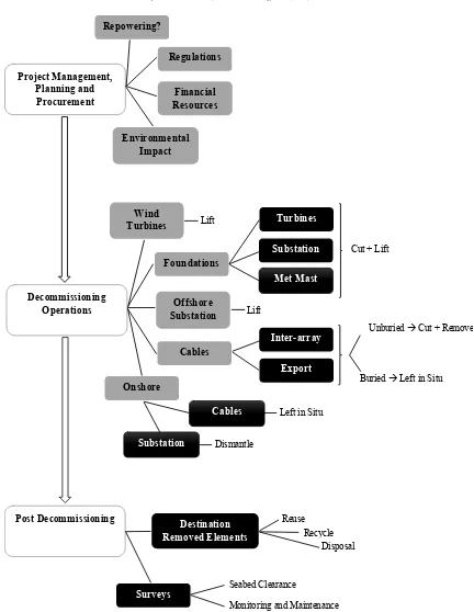
Fig. 2 displays the different phases involved in the decom-missioning of an offshore wind farm. The boxes on the left define the 3 main stages (blue), middle boxes state the factors that
in-fluence these (green), and the ones to the right (orange) are sub-elements affecting the previous ones:
3.1. Elements to remove
The structures that constitute a wind farm require different actions to be removed and will usually require specific equipment.
3.1.1. Turbines
Wind turbines should be entirely removed from the site and then dissembled onshore. The process begins de-energising and isolating the turbine from the grid. A heavy lift vessel or dynamic positioning vessel will be usually used, so it has to be mobilised to the location. As there are different methodologies used to install a wind turbine, there will also be several ones to dissemble it. The procedure performed will depend on the size and weight of the turbine, and will determine the lifting capacity and vessel’s deck space. The majority of procedures proposed are the reverse of the installation techniques practised to date [19]. The disconnection
procedures of the elements involved in a wind turbine will differ, including the location of cutting cables.
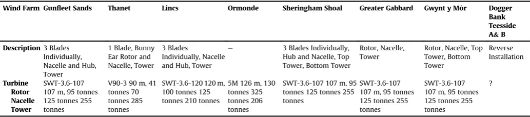
From the different publically available decommissioning pro-grammes[24e31], a summary table of preferred methods has been created (Table 1).
The turbines’specifications have been taken from the manu-facturers’websites.Table 1shows that the Siemens SWT-3.6-107 is the preferred installed turbine, and that the heaviest individual part to lift is the nacelle of the 5 MW 5M Senvion turbine. If the turbine was lifted as one piece, the heaviest case would again be the 5M Senvion turbine, with a total weight of 661 tonnes.
To start with the process, liquids such as gear or motor oils and any other chemicals that can be present, either can be collected and removed from the turbine for a later satisfactory treatment, or left inside the nacelle to minimise spillage risk and be collected once onshore. Bolts will be removed using normal methods or with angle grinders and plasma cutters if thefirst option is not possible
[28]. Interconnecting cables to adjacent structures need cutting, but it will depend on the method chosen. While the tower is being lifted, the foundation is prepared for removal. The vessel necessary will be reliant on the removal option performed: a self-propelled vessel thatfills its deck capacity returns to port, or a smaller jack-up for lifting procedures and barges used for transportation.
The best methodology will involve a reasonable operating time, with reduced risk to personnel (so containing a considerable number of heavy lifts) and that is economical to perform.
3.1.2. Transition piece
The transition piece is the structure connecting the lower part of the turbine tower to the foundation, usually by means of a bolted
flange connection. It contains elements such as J tube cable guides, access ladders and platforms[30], and will usually weigh around 300 tonnes[29]. The cables interconnecting the turbine’s tower will be disconnected and cut, and then the connection to the founda-tion, making the lifting operation possible. A cutting tool needs to befitted under the airtight platform of the transition piece while the J-tubes are cut. The cutting of the transition piece will start when the crane is in position to support the load[26]. Another option is to lift the transition piece all together with the foundation
[29], but this means a lifting of a large weight of around 1000 tonnes (which will depend on the type of wind turbines the wind farm has), requiring specialised cranes and extreme safety measures.
3.1.3. Foundations
The operations performed will mainly depend on the type of foundation. Specialised vessels are required due to the heavy lifting as consequence of the high weight of the foundations. As a general rule, after the removal of the J-tubes, internal access to the foun-dation is gained. A cutting method is then used to take out the external J-tubes and cut the foundation where it has been decided in the decommissioning programme, making lifting possible[28].
There are two removal options proposed: the complete removal of the foundation, or the cutting from a certain depth below the mud line and leaving the rest in situ, so that it will not disturb the site’s activities[29].
Cutting and leaving in situ the rest is usually the preferred op-tion as it reduces the risks, it is more economical to perform, and the site is disturbed less. Landfilling will be necessary to cover the hole left after the foundation is removed[28]. The foundations’
removal operations will be fairly dissimilar depending on the type of foundation. This is expanded below.
either remotely operated vehicles (ROVs) or divers. The chosen vessel will be mobilised to the site, and can be afloating crane, jack-up barge or special offshore unit with stabilising legs[28]. If the foundation is covered with scour protection, it has to be removed, allowing access for the cutting process. The excavation can be done with a sea trencher (or equivalent)[28]. The crane hooks from the vessel are positioned and attached to the lifting points of the foundation. The piles are cut below the seabed, but the distance will depend on the type of seabed, and the wind farm’s
decommissioning programme (usually a few meters beneath the mud line), so excavation equipment will be necessary.
The size of the piles, the penetration depth into the seabed and its weight makes it very complex to remove the entire structure, involving big risks to personnel, and great environmental impact due to deeper excavation and disturbance. Moreover, specialised equipment is required during longer periods, which means it is a more expensive and a less practical option than cutting[30]. The further down into the seabed the monopile is cut, the more
Lift
Cut + Lift
Lift
Unburied ÆCut + Remove
Buried ÆLeft in Situ
Dismantle
Reuse Recycle
Disposal
Seabed Clearance
Monitoring and Maintenance Left in Situ
Project Management,
Planning and
Procurement
Decommissioning
Operations
Post Decommissioning
Regulations
Repowering?
Wind
Turbines
Foundations
Offshore
Substation
Cables
Turbines
Met Mast
Substation
Onshore
Financial
Resources
Inter-array
Export
Substation
Cables
Destination
Removed Elements
Surveys
Environmental
[image:4.595.85.517.54.612.2]Impact
expensive and risky it becomes.
The cutting methods proposed are usually either diamond wire cutting or water jetting (with a remotely operated high pressure water/grit tool)[24], but the one that damages the least should be used. Any debris found needs to be removed too. The detached foundation is then loaded onto the chosen transportation vessel, and shipped shore when the vessel has full capacity.
3.1.3.2. Gravity. There is a conflict on what to do with this type of foundation. A marine habitat will have established around the foundation when it is time to decommission, so there are two op-tions: to leave the base of the foundation and cut the tubular sec-tion, or to remove it entirely. The second option will be compulsory if it implies a navigational hazard or there is an environmental preference.
The operations will start with ROVs or divers, as done with the monopile foundations, establishing the base structural integrity and placing the lifting attachments if required. The ballast from the base has to be removed and disposed, and so the mobilisation of a vessel capable of suction dredging is essential, inspecting with ROV’s or divers that it is correctly done. Below the foundation there are compacted sediments that need to be disaggregated, enabling the foundation to be lifted out from the seabed. Once this is done, it will be loaded onto a transportation vessel. The seabed will be inspected searching for debris to remove[31].
3.1.3.3. Jacket. This structure can be lifted in a single lifting oper-ation by cutting through each of its legs at a considerable level below the seabed. The legs consist of a pile driven into the seabed, a stub pipe at the bottom of the structure, and groutfilling the space between them. Lift rigging needs to be installed from the jacket to the crane vessel before the legs are cut, which is usually done with a diamond wire cutting tool and with the help of ROVs (in order to minimise risks to safety). Excavation on the seabed is required to reach the location of cutting. Once the four legs are cut, the struc-ture can be completely lifted and loaded onto a transportation vessel. While onshore, the steel can be recycled[27].
3.1.3.4. Bucket/suction. Regarding this type of foundation, a pump system is used to apply pressure inside the buckets and enables the release and extraction of the foundation from the seabed. The pumping of seawater or ballast from inside the foundation makes the structure buoyant, easing the process of capture onto a vessel for its later transportation[31]. Moreover, it has less environmental disruption due to no excavation or cutting requirements and the foundation can be completely removed.
3.1.4. Offshore substation
The structure can be divided into two parts: the topside, and its foundation. The topside is transported onshore as a single
structure, and can befilled either with oil or resin, so itfirst has to be emptied reducing the potential risk of spillage[28]or safely contained [26]. The techniques developed will be alike for the turbines. It is important to asses any potential hazard or pollutants that could appear during the operation, as well as mitigation pro-cedures, to allow their elimination.
The mobilisation of a decommissioning vessel capable of lifting the topside, and then its foundation is necessary. The topside will usually be the heaviest component of the farm [28]. When the vessel is ready, thefirst step is to disconnect the substation from the grid and de-energise it. Lifting points need to be installed followed by cutting the welded stab-in connections between the substation and the foundation, so that both structures can be lifted separately. Once they are loaded onto the vessel, they can then be transported onshore to correctly process them.
3.1.5. Meteorological mast
The meteorological mast will be decommissioned using a similar process to the turbine’s tower, and its foundation will depend on the type, as it was previously mentioned[29].
3.1.6. Subsea cables
Subsea cables include both inter-array cables and export cables. They are usually buried into depths of more than a meter below the seabed[31], which will not pose safety risks for marine users and have limited environmental or pollution impacts[28]ealthough this depends on the cable technology adopted.
Cables can be partially or wholly removed, but this will gener-ally depend on if the cable is buried or not, as the total removal of covered cables will involve extreme costs. Monitoring is important so that cables do not become exposed, and if this happens, appropriate burial actions are carried (using ROVs)[28].
It is possible to consider that the recovery is necessary only in some areas (cable crossings), and so the process starts with locating the cables (which may involve use of ROVs). Flow excavation and grapnels can be used to raise the cables from the seabed, cutting the required sections, and weighting and returning the remaining ends to the seabed, or by lifting cable ends onto a retrieval vessel where they are spooled onto a drum. If subsea trenches are formed, they will be naturallyfilled by tidal action[24]. The cables will be cut as near as possible from the foundation, burying the ends to a depth of around 1 m, and minimising disruption on the marine habitat and seabed [29]. The cables are transported onshore for suitable treatment.
[image:5.595.36.553.84.198.2]The complete removal is considered to cause substantial dam-age and disruption to the seabed given the extensive length of the cables[32]. There would be need for excavation to pull them out of the trench, and then cutting, which involve high costs[29]. Leaving the cables in situ and well buried is therefore the best opportunity suggested till date, though this may require some study of marine
Table 1
Methods proposed in the decommissioning programmes. Source: Authors Analysis[24e31].
Wind Farm Gunfleet Sands Thanet Lincs Ormonde Sheringham Shoal Greater Gabbard Gwynt y Mor^ Dogger
Bank Teesside A&B
Description3 Blades Individually, Nacelle and Hub, Tower
1 Blade, Bunny Ear Rotor and Nacelle, Tower
3 Blades
Individually, Nacelle and Hub, Tower
e 3 Blades Individually, Hub and Nacelle, Top Tower, Bottom Tower
Rotor, Nacelle, Tower
Rotor, Nacelle, Top Tower, Bottom Tower
Reverse Installation
Turbine Rotor Nacelle Tower
SWT-3.6-107 107 m, 95 tonnes 125 tonnes 255 tonnes
V90-3 90 m, 41 tonnes 70 tonnes 285 tonnes
SWT-3.6-120 120 m, 100 tonnes 125 tonnes 210 tonnes
5M 126 m, 130 tonnes 325 tonnes 206 tonnes
SWT-3.6-107 107 m, 95 tonnes 125 tonnes 255 tonnes
SWT-3.6-107 107 m, 95 tonnes 125 tonnes 255 tonnes
SWT-3.6-107 107 m, 95 tonnes 125 tonnes 255 tonnes
current action to establish the risk of the cables becoming exposed.
3.1.7. Scour protection
Marine life will have flourished around scour protecting any element of the wind farm, therefore it is sometimes difficult to determine if it is better to remove it, or leave it. As a general rule, scour will be left in situ, but if it is considered preferable to be recovered, then it will be dredged and shipped for reuse, or to a disposal site.
If there is rockfill, the individual boulders can be collected with the help of a grab vessel, loading them on a hopper barge and transporting them for reuse or disposal. If there are frond mats, concrete aprons or other cable protections, a crane vessel is used, and their recycling can be studied[31].
3.1.8. Onshore elements
There is still no requirement for the decommissioning of the onshore cables from an offshore wind farm, so their complete removal might not be considered. Any onshore cables that are buried can be studied to be left in situ where appropriate, as the potential environmental impacts involved will be similar to the ones during the installation. The onshore converter substations and any other structures must be properly dismantled, restoring the land to its original state[31].
3.2. Cutting techniques
Extensive cutting work is required during the decommissioning of this type of projects. There are several options available, of which some have been stated previously: diamond wire cutting [33], water jetting[34], and explosives[35]. When a wind farm reaches to its decommissioning time, better techniques may be available, and will need to be studied. The options available are as follow:
Diamond wire.The cut is a consequence of the friction pro-duced by the wire against the structure. Its advantages are that there are no vibrations, it is less pollutant, it can be wrapped around almost any size or shape and it is a cost effective solu-tion. As a drawback, it requires a good access to the cutting area
Water jetting.A jet of water and an abrasive substance released at high pressure. It can cut any material and can be easily automated but components fly off and the environment is affected more. It also comprises higher costs.
Explosives.A lined or unlined cavity in the explosive produces a high energy cutting jet. Low time is required and there is enough experience in controlled demolition of structures by this means. Usually non explosive methods are preferred because it in-creases the risks and needs a lot of planning and there is more disruption of the marine environment.
The preferred cutting technique will be diamond wire the cut-ting as piles should not be too complicated to wrap around, it is economical, and there is little marine disruption.
3.3. Destination of removed elements
A significant decision concerning the decommissioning plan-ning is to select what to do with all the structures once they are onshore. The structures should be disassembled into the different materials they are made of, so that the material can be then pro-cessed. Where possible, a prioritisation should be done and being the option for reusing thefirst. If this alternative is not valid, it will be followed by recycling the materials that comprise the removed elements. As last, meaning that the other two options are not valid, disposal (landfill)[36].
3.4. Vessels
The logistics involved in the decommissioning process is an essential part of the planning. A methodology that comprises low risks, costs and reducing the operating time, would be ideal. There are numerous vessels that can be chartered, but there is still no single correct answer to which one(s) is/are adequate to use. The factors that influence which vessel to choose depend on the number of turbines and foundations to remove (space availability on the deck), their weight (crane capability), the site’s water depth and seabed type (not all vessels can work on all seabeds), and the market availability[37]. The methodologies carried out to remove the turbines and the foundations will also need to be known to search for the best combination possible.
Apart from deciding what vessel(s) carry out the removal op-erations, it is important to choose an appropriate transportation strategy. This will depend principally on the distance to port and the number of wind turbines the wind farm has. There are two options[38]:
Multitask decommissioning vessel.The vessel is required to do both the removal operations and the transportation of the components to port. There can be more than one vessel doing the job to reduce the decommissioning period, but the costs would also increase.
Decommissioning vessel and transportation vessel. The decommissioning vessel is used only for the removal of the structures, and they are loaded into another barge that ships them to shore. There could be more than one barge so that the decommissioning vessel does not have to wait till it returns to continue working.
3.5. Decommissioning programmes
For the purpose of this article, all the decommissioning pro-grammes available have been studied into detail. On the one hand, similar characteristics have been identified in the reports such as that buried cables will be left in situ, monopile foundations will be cut at a minimum depth of 1 m below the seabed and then lifted, and the same for the offshore substations’jacket foundations.
On the other hand, each wind farm has different number of wind turbines, meteorological masts, substations, distance to shore and depth, seabed materials, weather conditions and cable length
[11] [40] [41]. This means that the programmes will be unique to each wind farm and will be difficult to generalise a methodology. Due to this, each wind farm will have its own schedule with different timings, and costs.
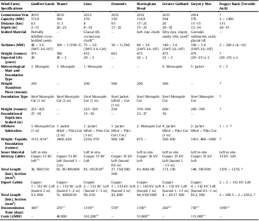
Table 2summarises this analysis making it easier for compari-son. The two factors that have been recognised to have the greatest impacts on the decommissioning programmes, need to be thor-oughly studied.
3.5.1. Time
A very important aspect of the decommissioning programme is how to manage and predict a correct timing for the operations to be done. The weather is one of the big challenges concerning this stage, as the environment itself can become hostile and unsafe for the personnel. The number of turbines and foundations the wind farm has, the distance to port and the methods and vessels used for the removal operations are also influencing factors. Due to this, planning has to be done precisely as high costs are involved. It is estimated that the time taken should be around 50e60% less than the installation time[42].
Table 2
Summary table of the decommissioning programmes available. Source: Author analysis[24e31].
Wind Farm/ Specifications
Gunfleet Sands Thanet Lincs Ormonde Sheringham
Shoal
Greater Gabbard Gwynt y M^or Dogger Bank (Teesside A&B)
Commission Year 2010 2010 2012 2012 2012 2013 2014 ?
Capacity (MW) 172.8 300 270 150 316.8 504 576 21200
Distance (km) 8.5 11.3 8 9.5 17e23 26 13e15 131
Depth (m) 2e15 20e25 8e18 17e22 15e23 20e32 12e34 20e35
Seabed Material Partially lithified cross-bedded sands
e Glacial till, cretaceous chalk*e
e Soft clay, chalk Silty clay, clayey, sandy silts, sand*l
Granular sediments, sand, glacial till
e
Turbines (MW) 483.6
(SWT-3.6-107)
1003 (V90-3) 753.6 (SWT-3.6-120)
305 (5M) 883.6 (SWT-3.6-107)
1403.6 (SWT-3.6-107)
1603.6 (SWT-3.6-107)
2200 x (4e10)
Weight (tonnes) 475 396 435 661 475 475 475 ?
Expected Life (years)
20 202 202 e 202 252 (20e23) x 2 (20e25) x 2
Meteorological Mast and Foundation Type
1: Monopile 1: Monopile 1: Monopile e e 6: Monoopile 5: Jacket 5þ5
Weight Transition Piece (tonnes)
230 e 290 500 200 300 e ?
Foundation Type Steel Monopile: Cut (1 m)
Steel Monopile: Cut (2 m)
Steel Monopile: Cut (1 m)
Steel Jacket: LiftedþCut (1 m)
Steel Monopile: Cut
Steel Monopile: Cut
Steel Monopile: Cut
?
Weight (tonnes) 225e423 e 225e320 250 370e500 660 200e700 ?
Foundational Depth into Seabed (m)
27e38 e 15e30 e 23e37 30 e
Offshore Substation
1: Monopile Cut (1 m)
1: Jacket liftedþPiles Cut (2 m)
1: Jacket liftedþPiles Cut (1 m)
1: Jacket liftedþPiles Cut (1 m)
2: Monopile Cut 4: Jacket liftedþPiles Cut (1 m)
2: Jacket liftedþPiles Cut
1þ1: ?
Weight: Topside, Foundation (tonnes)
1315, 414*a 1460, 820 2250, 970 900, 540 875,e 500, 850 1415, 400e1000 ?
Scour Material Left in situ e Left in situ e Left in situ Left in situ Left in situ Left in situ
Interray Cables Copper 33 kV: Left*b
Copper 33 kV: Left (buried 1e 2 m)
Copper 33 kV: Left
Copper 33 kV: Left (buried 0.6 m)
Copper 36 kV: Left
Copper 33 kV: Left (buried 1 e1.5 m)
Copper 33 kV: Left
33 kV: Left
Total Length (km), Section (mm2)
36, 500/150 65, 95/300/400 85, 185/630*f 27, 150/300/ 500
83, 400/185 173, 150 148, 185/500 1270þ1270, ?
Export Cables Copper
1132 kV: Left (buried 2 m)
Copper 2132 kV: Left (buried 1e2 m)
Copper 2132 kV: Left (buried 1e3 m)
Copper 1132 kV: Left (buried 2 m)
Copper 2145 kV: Left (buried 1 m)
Copper 4132 kV: Left (buried 1e1.5 m)
Copper 4132 kV: Left (buried 0.5e1 m)
22132 kV: Left
Total Length (km), Section (mm2)
9.3, 800 51, 1000/630 96, 630 43, 800 44, 630/1000 445.5?, 800 85.2, 500 2260.5þ2220.2, ?
Decommission Time (days)
100*c 270*d 1339*g 570*i 1350*j 260*m 730*n 1095*p
Costs (£/MW) e 40,000 101,200*h e 31,900*k e 111,000*o e
If no data was found a“e”is used. If it has yet not been decided a“?”is used.
In Dogger Bank there are two wind farms included (A&B). aFoundationþtransition piece.
bRemove any uncovered cables.
c Project management, planning and procurement: 40 daysþOffshore decommissioning: 60 days.
d Each WTG: average of 2 days to decommission, load and transport to shore (after taking weather downtime in consideration), offshore substation: up to 3 weeks. It is
probable to require 24 h working. Total: 9 months.
eLincs seabed: The surface is made of marine deposits consisting of sandy and gravelly sediments estimated to be 1 m thick, then glacial till is found (5e13 m) and after that
crestaceous chalk extends 100e200 m in depth. f 64 km of 185 mm2and 20.5 km of 630 mm2.
gProject management, planning and procurement up to 36 months. Decommissioning operations: 259 days (163 turbines).
hIncludes vessel time and ancillary activities. These costs assume the disposal costs of the bulk materials once transported to onshore equate to the scrap value of the assets.
Total cost of£27,322 k.
iProject management, planning and: 180 daysþPre-survey, isolate, cut cables, remove or bury cut ends, remove exposed lengths: 25 days (plus weather window downtime)þRemove topsides, jacket and foundations: 60 days (plus weather downtime). To allow for efficient scheduling of crane vessels during appropriate weather windows, this may take place up to 360 days after all cables have been cut. Post work survey: 5 days (plus weather downtime) plus 30 days for analysis.
jProject management, planning and procurement and contract follow-up: 36 monthsþoffshore decommissioning: 6e12 months (taken average of 9) - decommissioning of 88WTGs: 200 days.
kExpected costs are 1,415,515 kNOK for the whole wind farm in March 2014. 30% Contingency included. Exchange rate used was: 1 NOK¼0.1006 GBP.
lStiff marine silty clay, clayey and sandy silts and subordinate sands. This formation is evident underneath the site and surrounding area to a depth of over 100 m. mProject management, planning and procurement: 90 daysþoffshore decommissioning: 140 daysþonshore dismantling and disposal: 170 days (run in parallel).
n2 years: 3652 days.
oThe decommissioning is expected to be£40,000/MW but have a budget of£400,000/turbine.
consuming is the project management, planning and procurement, but it is not included in all the reports. Moreover, it is questionable that the decommissioning time expected for Lincs (75 turbines) is twice the one predicted for Greater Gabbard (140 turbines). With the help of these results it can be predicted which report has been too optimistic and which has been more realistic, though it should be recognised that not all factors can be captured here (E.g: seabed bathymetry and sediment composition will both influence the ease of these operations).
3.5.2. Costs
The estimated cost for decommissioning an offshore wind farm is around 2e3% of the total capital cost. This means that the developer needs to save money during the life cycle of the wind farm in order to be able to pay its end of life. The middle life accrual is the preferred mechanism as funding structure, and consists of starting to save money when the wind farm is in the middle of its operational period[43].
The decommissioning has to be carefully planned because if it is required earlier than programmed, this will increase the costs (and will involve less benefit too). The availability of the vessels is a crucial factor for the planning and will determine when the decommissioning operations can be done, comprising a large amount of the costs[44]. A breakdown of the costs can be found in
Fig. 3.
The removal of the foundations is found to be nearly half of the total costs, as these are very heavy structures that require complex techniques and specialised equipment. The other important value is referred to the disassembly operations, as it will have a lot of time consuming activities.
The majority of the reports do not mention costs or refer to them as confidential values.Table 2shows a wide range of costs. This is because the costs are affected by the type of foundation, the loca-tion of the wind farm and the availability of technical expertise and equipment. Thefirst cost prediction was of around£40,000/MW
[43], but as years have passed these values have changed. DNV GL estimated in a recent study that decommissioningfigures could be between V200,000e600,000/MW [39], meaning 60e70% of the
installation costs[23]. These costs are expected to decrease once experience is gained. Furthermore, it can be seen that the projected costs for Sheringham Shoal are very large compared to the others. This could be conservatism on the part of the owner/operator, a reflection of the sites complexity, or due to an error in the decommissioning programme’s calculations.
4. Modelling decommissioning time and costs
It has been revealed that the published decommissioning pro-grammes have very dissimilar decommissioning timings and costs per MW installed, motivating further research into the decom-missioning programmes. To achieve this, a model taking into ac-count the key variables that affect the decommissioning operations has been designed, modelling all the sites and their characteristics included inTable 2. The model is implemented in MSExcel. The modelling presented focuses on turbines and support structures. Offshore substations and cables were excluded from the model due to a lack of input data, and will be captured in future modelling activity. It is therefore expected that the model outputs will be optimistic. The two transportation strategies previously mentioned have been modelled to recognise which is best to use depending on the wind farm’s characteristics.
4.1. Self-transportation model
The vessel chosen to perform the tasks of removing the wind farm’s elements and then ship them to shore is a Wind Turbine Installation Vessel (WTIV). For the purposes of this study the specifications are: transit speed up to 10 knots, 1500 tonne lift ca-pacity, deck capacity for 10 turbines or 8 foundations, daily price is of£150,000 and the mobilisation£300,000. With this vessel, two scenarios have been modelled: using just one WTIV and using 2 WTIVs working in parallel.
4.2. Multi vessel transportation model
In this case, a non-propelled Jack Up has been chosen to carry
40%
19%
6%
35%
Decommissioning Costs Breakdown
O
ff
shore Prepara on
Vessel Mob/Demobilisa on
Disassembly
[image:8.595.88.517.478.729.2]Founda on Removal
out the removal operations while two barges work in parallel on the transportation. It is possible to optimise [45]the number of barges used but this is not the focus of the current study. The Jack Up has a lifting capability of 1000 tonnes, a dayrate of£75,000 and a mobilisation cost £200,000. Regarding the barges, they are assumed to have a speed of 10 knots, a capacity of 8 turbines and 6 foundations, a daily price of £50,000 and mobilisation cost of
£100,000.
4.3. Results: preferred transportation strategy
This model has enabled the comparison of different site char-acteristics and the time and costs they would comprise.Fig. 4 vi-sualises the modelled decommissioning time for each site.
As expectedFig. 4shows that for all sites the decommissioning time is greatly reduced 2 WTIVs are used. The only wind farm that has a greater published estimated time than the modelled one is Ormonde, meaning that their decommissioning planning could be conservative. Thanet, Lincs and Sheringham Shoal are close to the modelled result if 2 WTIVs work in parallel or if the multi vessel strategy is used. For Gunfleet Sands and Greater Gabbard, the only modelled strategy that wouldfit in their timing would be the 2 WTIVs. Moreover, the distances that have been used on the model do not affect notably the decommissioning time. The average decommissioning time in the reports is nearly 1 day/MW, being for one WTIV 1.34 days/MW, for multi vessels 1.27 days/MW and the least for 2 WTIVS 0.67 days/MW. Compared to the modelled times the majority of reported assumptions seem optimistic.
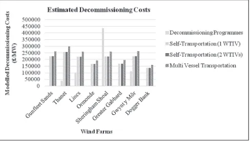
Fig. 5shows the modelled decommissioning costs for each wind farm.
As previously mentioned, not all the decommissioning pro-grammes included their expected costs, hence the comparative data inFig. 5are incomplete, however all sites except Sheringham Shoal have been predicted confidently. Moreover, the modelled cost for 2 WTIVs is similar to a single WTIV because there are half days to pay for but double mobilisation costs. The most expensive method is the multi vessel strategy as there are 3 vessels to pay for. Furthermore, Dogger Bank involves the least costs as there is more operation time due to the high capacity the wind farm has, and so the mobilisation costs are compensated. The average costs for all the means of transport are over£200,000/MW, which is more than the average predicted in the decommissioning programmes (£86,000/MW).1
As a result of this analysis, it has been concluded that the ideal transportation method to use is 2 WTIVs working in parallel as it has the least decommissioning time and the costs are reasonable. However, these initial results should be treated with caution before a full sensitivity analysis is carried out. This will be addressed in future work.
5. Summary of key results
As a result of the analysis of the whole decommissioning pro-cess, and the identification of the merits and drawbacks of numerous stages, now it can be stated the best and most sustain-able methodology to follow, as well as the transportation strategy to optimise time and costs.
5.1. Proposed decommissioning methodology
Turbines:It is known that the turbine removal operations can be delayed if there is too much wind. As the wind farms are placed in windy areas, this can be a problem. Moreover, as previously seen, the less offshore disassembling the better. Regarding this, and as there are specialised vessels capable nowadays, the suggested op-tion would be to lift the turbine as a single structure. It will involve heavy lifting operations, but it will be nothing compared to the offshore substation’s topside lifting (5M Senvions’ turbine in Ormonde was the heaviest turbine studied with 661 tonnes, while Linc’s topside was 2250). These operations will implicate high risks, but due to the similar operations being performed in the oil and gas sector, by the time decommissioning gets near, eventually there will be enough experience. No liquids (oil or any other) will be collected offshore to avoid the risk of spillage.
Transition piece:Lifted together with the foundation, as the total lift is estimated to be less than 1500 tonnes, being again, a smaller value than for the topside. There are specialised vessels available to perform these operations, no cutting will be required, and by the time decommissioning happens, there will be experience.
[image:9.595.305.550.68.209.2]Foundations:Concerning the monopile and jacket foundations, they will be cut into a depth more than 1 m below the mud line, so that the environmental impact is minimised and the process becomes more sustainable. Then, they can be lifted. In the case of gravity and suction foundations, no cutting will be necessary, and will be completely lifted after their corresponding actions. As it can be seen fromTable 2, the foundations installed until now, are mainly monopiles driven into the seabed at an average of around 20 m, meaning that the majority of the pile will be left in the site.
[image:9.595.306.550.248.387.2]Fig. 4.Estimated decommissioning time per MW. Source: Authors Analysis.
Fig. 5.Estimated decommissioning costs. Source: Authors Analysis.
Offshore substation:Regarding the topside, no liquids will be collected offshore (oil or resin) to reduce the spillage risk, and will be lifted as a whole piece. This can involve very heavy lifting cranes depending on the substation, as Lincs’ topside (2250 tonnes). The foundation will be treated as mentioned before. Meteorological mast:It will be lifted in just one piece, similar to a turbine tower. The foundation as above mentioned.
Subsea cables:The inter-array and export cables can be left in situ if their burial depth is more than 1 m. In the case of burial depths of less than 1 m, or unburied cables, they will be cut where they become buried to a meter, and then removed. Monitoring of the buried cables shall be done to verify that they are correctly buried, if not, actions shall be taken.
Scour protection:If there is any, as a general rule it will be left in situ, as life will haveflourished and so it is not disturbed. If it is recognised to become a hazard, it will be dredged.
Onshore elements:Buried cables will be left in situ to reduce the environmental impacts and any building or structure will be completely dismantled to restore the site to its initial characteristics.
Cutting techniques:Diamond wire will be the preferred tool for the cutting operations as it is the least environmental harmful, can work in a wider range of monopile diameters and it is economical. Destination of removed elements: The first option will be to reuse, but only turbines that are relatively new and that have still an expected life of more than 10 years. The rest will be recycled as second option. All the materials that cannot be recycled will be landfilled.
Transportation strategy:The results showed that the best trans-portation scheme was to use 2 WTIVs working in parallel, as the costs are similar to one WTIV but halving the decommissioning time. Additionally, the higher the capacity the wind farm has, the more decommissioning time it will take. As a result, the mobi-lisations costs will be compensated and so the overall costs would be reduced. Furthermore, there are elements that are becoming too heavy and that require specialised heavy lifting vessels.
6. Fields for future research
As well as with the installation process, the decommissioning will depend on many factors that are dissimilar for each site. There is still need for investigation on the main challenges concerning the decommissioning stage:
Turbine removal.There are many alternatives for disassem-bling offshore wind turbines; ones with fewer lifts but heavier, others with more but lighter lifts. Experience is required to confirm which one could be the best ones to implement, but this will probably not have a unique solution.
Space optimisation. Vessel’s decks areas are limited, so an efficient planning of the use of space is required to achieve a resourceful way of transportation. An important fact that is not being considered in the decommissioning programmes is how the turbines, transition pieces and foundations, once loaded on the transportation vessel, arefitted and held. The elements can be welded onto the deck or a prefixed rack can be used, they can be positioned vertically or horizontally, but these decisions will be constrained by the stability of the vessel, the element’s weight, and the existing space.
Planning, time scale and costs.These are the most important factors of the process, as if any of these are not well organised, the costs can increase dramatically. The weather needs to be meticulously considered as the work is done in a hostile envi-ronment. The operations are preferred to be done during sum-mer, trying to avoid winter. Two summers might be a better
option than operating during a whole year, but these needs further investigation as costs is an important factor.
Correct data management. A lot of information is lost from stage to stage during the lifecycle of a project, and this infor-mation can be crucial reached the decommissioning stage. Due to this, an accurate management of data is something that needs to be achieved throughout the project’s life.
7. Conclusion
There is no unique solution on which could be the best meth-odology to follow to decommission an offshore wind farm. Factors such as reducing time, costs and environmental impacts are the main aspects that will influence the decision on which method to carry out.
Design decisions should, as far as possible, result in installations which are affordable to install and eventually remove, but it is recognised that some elements, such as deep foundations, may nonetheless be costly to remove. Making lighter structures could ease lifting operations, but this is contrary to recent design trends for bigger turbines. On the other hand,floating foundations will simplify installation and decommissioning operations, and as a result, reduce the decommissioning costs[46].
Plans are designed on a lowest common denominator when referred to costs. This means that a 50 years lease may not imply a repowering when the time arrives. The lifetime expectancy for an offshore wind farm is between 20 and 25 years, but repowering can be studied before dismantling. This would involve removing the existing turbines (decommissioning operations) and substituting them with more potent ones which are larger and so fewer are needed. Foundations could be designed to behave greater retrofit capability and have a longer life expectancy, reusing them to place the repowered turbines. However, no existing offshore sites have been designed in this way and there is scarce data on the individual duration of components.
There is still a large amount of uncertainty when referred to the decommissioning of this sector and one of the most important factors that will influence the whole process is the life expectancy of the project. Yttre Stengrund was decommissioned after 14 years of operation [39] while Vindeby will be decommissioned after more than 25 years[4], but these are still small prototype projects. If projects do not run as long as they have been expected, this will have great impacts on the actual optimistic decommissioning planning of the wind farms and on their economics.
The availability of specialised vessels is one of the major chal-lenges in the offshore sector. Thefluidity of the price of oil makes predictions about future vessel costs extremely challenging. One way to hedge this risk would be to build a supply-demand curve for heavy lift vessels[44]. However even if oil prices remain at recent historic lows, there will be a large future demand due to oil and gas decommissioning and further marine energy construction activity. The time taken for decommissioning activities will mainly depend on which methodologies are used in each phase as well as the selected transportation strategy. One of the most influencing factors in the decommissioning time is water depth, which
in-fluences foundation design and weight. It has been estimated that the complete removal and transportation to shore per MW is around a day, which seems to indicate that the predictions made in the published decommissioning programmes are optimistic.
the operational phase is the sharing of vessels[37]. However, this is probably impractical for decommissioning as it is such a vessel-intense process and involved little inactivity.
This paper has found that the published decommissioning programmes are often optimistic regarding time and cost. This is in part because the costs of decommissioning, when viewed at the start of the project (when the plan is written), arefinancially dis-counted by 20e25 years and thus initially appear small. More investigation should be carried out to reduce and/or defer these future costs, either by facilitating life extension for offshore wind assets or by much more detailed modelling and planning of decommissioning processes.
Acknowledgements
This work was supported by the Engineering and Physical Sci-ences Research Council (EPSRC) with grant number EP/L016680/1.
References
[1] J. Welstead, R. Hirst, D. Keogh, G. Robb, R. Bainsfair, Scottish Natural Heritage Commissioned Report No. 591, Research and guidance on restoration and decommissioning of onshore wind farms, 2013.http://www.snh.org.uk/pdfs/ publications/commissioned_reports/591.pdf.
[2] Decommissioning of Offshore Renewable Energy Installations under the En-ergy Act 2004, Department of EnEn-ergy and Climate Change, 2011.https://www. gov.uk/government/uploads/system/uploads/attachment_data/file/80786/ orei_guide.pdf.
[3] The First Offshore Wind Farm Decommissioning Complete, 2016. The Mari-time Executive. MarEx, http://www.maritime-executive.com/article/first-offshore-wind-farm-decommissioning-complete.
[4] DONG announces Vindeby decommissioning e Wind Power Offshore. D. Weston, 2016. http://www.windpoweroffshore.com/article/1382887/dong-announces-vindeby-decommissioning.
[5] Vattenfall Starts First Ever Offshore Wind Farm Dismantling, The Norwegian Wind Energy Association (NORWEA), 2015. http://www.norwea.no/ nyhetsarkiv/visning-nyheter/vattenfall-starts-first-ever-offshore-wind-farm-dismantling.aspx?PID¼1145&Action¼1.
[6] Wind Energy Regions: DenmarkeSouth Baltic Offshore Wind Energy Regions. http://www.southbaltic-offshore.eu/regions-denmark.html.
[7] C. Januario, S. Semino, M. Bell, Offshore Windfarm Decommissioning: a Pro-posal for Guidelines to be Included in the European Maritime Policy, 2007. https://www.researchgate.net/publication/228636135_Offshore_Windfarm_ Decommissioning_A_proposal_for_guidelines_to_be_included_in_the_ European_Maritime_Policy.
[8] E. Lantz, M. Leventhal, I. Baring-Gould, Wind Power Project Repowering: Financial Feasibility, Decision Drivers, and Supply Chain Effects, National Renewable Energy Laboratory, 2013. http://www.nrel.gov/docs/fy14osti/ 60535.pdf.
[9] The First Decommission in the World of an Offshore Wind Farm Is Now Complete, Vattenfall Press Release, 2016. https://corporate.vattenfall.com/ press-and-media/press-releases/2016/the-first-decommission-in-the-world-of-an-offshore-wind-farm-is-now-complete/.
[10] Lorc KnowledgeeList of Offshore Wind Farms. http://www.lorc.dk/offshore-wind-farms-map/list.
[11] Telford, Stevenson, MacColl Wind Farms and associated Transmission Infra-structure Environmental Statement, Technical Appendix 1.3 E: Preliminary Decommissioning ProgrammeeMoray Offshore Renewables Ltd.http://77.68. 107.10/Renewables%20Licensing/EDPR_UK_and_REPSOL_Offshore_ Windfarm/ES/Volumes%208%20to%2011%20-%20Technical%20Appendices/ Volume%208%20-%20The%20Project%20Technical%20Appendices/Appendix% 201.3%20E%20-%20Preliminary%20Decommissioning%20Programme.pdf. [12] Offshore Wind Operational Report, 2015. The Crown State, http://www.
thecrownestate.co.uk/media/5462/ei-offshore-wind-operational-report-2015. pdf.
[13] Counting CostseDecommissioning an offshore wind farm assets. Renewables Consulting Group. S. Freeman.http://renewablescg.com/wp-content/uploads/ 2015/12/Counting-Costs-Decommissioning-of-offshore-wind-farm-assets.pdf. [14] DecommissioningeOil&Gas UK.http://www.oilandgasuk.co.uk/economic_
report/decommissioning.cfm.
[15] L. SmågeBreidablikk, Heavy Lift Methods in Decommissioning Installations, Norwegian University of Science and Technology Department of Marine Technology, 2010.https://core.ac.uk/display/30857507.
[16] E. Uraz, Offshore Wind Turbine Transportation & Installation Analyses: Planning Optimal Marine Operations for Offshore Wind Projects, Gotland University, 2011. http://www.diva-portal.se/smash/get/diva2:691575/ FULLTEXT01.pdf.
[17] M.C. O’Hara, The legal and regulatory framework governing offshore decommissioning, Constr. Law J. 31 (3) (2015) 122e138.
[18] M.J. Kaiser, B.F. Snyder, Offshore Wind Energy Cost e Installation and Decommissioning, Springer, 2012.
[19] O. Yanguas Mi~nambres, Assessment of Current Offshore Wind Support Struc-tures Concepts: Challenges and Technological Requirements by 2020, Karl-shochschule International University, 2012.http://e-archivo.uc3m.es/bitstream/ handle/10016/16597/PFC_Oscar_Yanguas_Minambres.pdf?sequence¼5. [20] C. Birkeland, Assessing the Life Cycle Environmental Impacts of Offshore Wind
Power Generation and Power Transmission in the North Sea, Norwegian University of Science and Technology Department of Energy and Process Engineering, 2011. http://daim.idi.ntnu.no/masteroppgaver/006/6222/ masteroppgave.pdf.
[21] Life Cycle Assessment of Offshore and Onshore Sited Wind Farms, Elsam Engineering, 2004. http://www.apere.org/manager/docnum/doc/doc1252_ LCA_V80_2004_uk%5B1%5D.fiche%2042.pdf.
[22] S. Properzi, H. Herk-Hansen, Life cycle assessment of a 150 MW offshore wind turbine farm at Nysted/Roedsand, Denmarkeenergi E2, in: European Wind Energy Conference and Exhibition, Copenhagen, (Denmark), 2001. https:// tethys.pnnl.gov/sites/default/files/publications/Middelgrund_LCA_2001.pdf. [23] Decommissioning: Should they stay or should they go? J. Dodd, WindPower
Monthly, 2015 http://www.windpowermonthly.com/article/1349270/ decommissioning-stay-go.
[24] Gunfleet Sands Decommissioning PlaneDong Energy, 2012.http://assets. dongenergy.com/DONGEnergyDocuments/Gunfs/DecommissioningPlan.pdf. [25] Thanet Offshore Wind Farm Decommissioning Plan, 2008.https://corporate.
vattenfall.co.uk/globalassets/uk/projects/decommissioning-plan-2008.pdf. [26] Lincs Offshore Wind Farm Decommissioning Plan, 2010. https://www.
centrica.com/files/pdf/centrica_energy/lincs_offshore_wind_farm_ decomissioning_plan.pdf.
[27] TC Ormonde OFTO Ltd Decommissioning Programme, 2013.http://www. transmissioncapital.com/pdf/BD%20ORM%20TEC%20002-2%20Ormonde% 20OFTO%20Decom%20Plan%20for%20Publication.pdf.
[28] Statoil Decommissioning Programme Sheringham Shoal e Scira Offshore Energy, 2014. http://www.scira.co.uk/downloads/Decommissioning% 20Programme%20SCIRA%20SC-00-NH-F15-00005_07.pdf.
[29] Decommissioning ProgrammeeGreater Gabbard Offshore Wind Farm Proj-ect.http://sse.com/media/92981/GGOWL_DecommissioningProgramme.pdf. [30] Decommissioning Strategy Gwynt y M^or Offshore Wind Farm LtdeRWE
Npower Renewables Ltd, 2011.https://www.rwe.com/web/cms/mediablob/ en/1268920/data/1202906/2/rwe-innogy/sites/wind-offshore/in-operation/ gwynt-y-mr/English.pdf.
[31] Dogger Bank Creyke Beck Outline Decommissioning StatementeForewind, 2013. http://www.forewind.co.uk/uploads/files/Creyke_Beck/Application_ Documents/8.3_Decommissioning_Statement_F-DVC-SP-001_FINAL_10-08-13.pdf.
[32] K. Smyth, N. Christie, D. Burdon, J.P. Atkins, R. Barnes, M. Eliott, Renewables-to-reefs? Decommissioning Options for the Offshore Wind Power Industry, Elsevier Marine Poll. Bull. 90 (2015) 247e258.
[33] Diamond Wire Cuttinge Castle and Pryor.http://www.castle-pryor.co.uk/ services/wire-sawing.
[34] Evaluation, Selection and Development of Subsea Cutting Techniques, AME Ltd., 1997.http://www.hse.gov.uk/research/othpdf/200-399/oth349.pdf. [35] E.K. Lauritzen, J.F. Gjødvad, C. Gormsen, Decommissioning of offshore
struc-tures by means of explosives eNIRAS, in: Decommissioning Conference, Esbjerg (Denmark), 2007.
[36] S. Bradley, End of Life Opportunities, Energy Technology Institute, 2014. http://www.eti.co.uk/wp-content/uploads/2014/06/End-of-life-for-offshore-wind-EI-June-2014UPDATED.pdf.
[37] Jack-up Vessel Optimisation e the Crown State, 2014. http://www. thecrownestate.co.uk/media/451536/ei-km-in-om-construction-072014-jack-up-vessel-optimisation.pdf.
[38] Offshore Infrastructure: Ports and Vesselse Offshore Renewable Energy Conversion Platforms Coordination Action. http://www.orecca.eu/c/ document_library/get_file?uuid¼
6b6500ba-3cc9-4ab0-8bd7-1d8fdd8a697a&groupId¼10129.
[39] K. Chamberlain, Offshore Operators Act on Early DecommissioningeWind Energy Update, 2016. http://analysis.windenergyupdate.com/offshore/ offshore-operators-act-early-decommissioning-data-limit-costs.
[40]] The Wind Power Database.http://www.thewindpower.net/. [41] 4C Offshore Database.http://www.4coffshore.com/windfarms/.
[42] G. Jackson, Offshore wind decommissioning, Constr. Law J. 31 (3) (2015) 148e151.
[43] Offshore Renewable Energy Installation Decommissioning StudyeClimate Change Capital. https://www.gov.uk/government/uploads/system/uploads/ attachment_data/file/47955/900-offshore-renewable-installation-decom.pdf. [44] Forecasting Long Term Jack up Vessel Demand for Offshore Wind. D. McMillan&
I. Dinwoodie.https://pure.strath.ac.uk/portal/files/27312713/mcmflt_v3.pdf. [45] E. Barlow, D.T.Oztürk, M. Revie, E. Boulougouris, A.H. Day, K. Akartunalı,€
Exploring the impact of innovative developments to the installation process for an offshore wind farm, Ocean Eng. 109 (2015) 623e634.
[46] A. Myhr, C. Bjerkseter, A. Ågotnes, T.A. Nygaard, Levelised Cost of Energy for Offshore Floating Wind Turbines in a Life Cycle Perspective, Elsevier Renew. Energy 66 (2014) 714e728.
![Fig. 1. Expected year of decommissioning of existing offshore wind farms. Source: Authors analysis based on [10].](https://thumb-us.123doks.com/thumbv2/123dok_us/1494507.102131/2.595.133.475.473.729/expected-decommissioning-existing-offshore-farms-source-authors-analysis.webp)
![Fig. 3. Decommissioning costs breakdown. Source: [43].](https://thumb-us.123doks.com/thumbv2/123dok_us/1494507.102131/8.595.88.517.478.729/fig-decommissioning-costs-breakdown-source.webp)