MANUAL MOBILE ROBOT FOR ROBOCON
Shivaraj a/l Samugam@Shanmugam
Bachelor of Mechatronic Engineering
“I hereby declare that I have read through this report entitle “MANUAL MOBILE ROBOT FOR
ROBOCON” and found that it has comply the partial fulfillment for awarding the degree of
Bachelor of Mechatronic Engineering”
Signature : ...
Supervisor’s Name : ...
xii
MANUAL MOBILE ROBOT FOR ROBOCON
SHIVARAJ A/L SAMUGAM@SHANMUGAM
This report is submitted in partial fulfillment of requirements for the degree of
Bachelor in Mechatronic Engineering
Faculty of Electrical Engineering
UNIVERSITI TEKNIKAL MALAYSIA MELAKA
xii
“I hereby declared that this report is a result of my own work except for the excerpts that
have been cited clearly in the references.”
Signature : ………
Name : ………
xii
Specially dedicated to my beloved family especially my mother (M.Anjalay Devi) and my father
(N.Shanmugam) for their support. To my project supervisor En.Ahmad Zaki Bin Haji Shukor for
ACKNOWLEDGEMENT
First of all, I would like to thank God for His blessings that lead to the success of
this project. I would like to express gratitude to my family for never ending support and
motivating me throughout the project development. My heartfelt appreciation to my Project
Supervisor, En Ahmad Zaki Bin Haji Shukor for supporting my decisions, ideas and
progress in this project. He has been a best guide and ideologist behind the development of
the project with the confidence and inspiration given to execute this project. Thanks to
Machine Workshop technician, Muhammad Azwan Bin Abdul Kadir for guiding me
during development of Mecanum wheels and other mechanical structure for the project.
Last of all, I would like to thank Robocon 2009 team members, Robocon lab technicians,
and related lectures for the support and contribution towards the accomplishment of this
ABSTRACT
This project presents the research, designing, and development of
multi-directional mobile robot using four custom-made Mecanum wheels for Robocon
2009 application. The Mecanum wheels that were designed and developed consist of
six passive rollers made from rubber and the wheel body made of Polyethylene (P.E).
The Mecanum wheels are autonomously controlled using four units of industrial
specification VEXTA AXHM230K-GFH brushless geared DC motors and the
motors were mounted directly to the robot platform constructed using an aluminum
frame. The wheels are directly coupled to the motor shaft for direct actuation and
precise control of each motor independently. IFC (Interface Free Controller)
microcontroller board with build in PIC18F MCU used to operate the robot. The
stackable boards contain a main board card, power card, two brushless motor cards,
and a PS2 joystick card. A fundamental multi-directional mobility developed using
MPLAB IDE programming software to analysis the basic mobility capabilities and
performance of the mobile robot that will counterpart Robocon environment. A
visual experiment was set-up to analyze the motion characteristic of the mobile robot
motion in Y and X axis, rotary motion, and finally diagonal motion. Mecanum wheel
mobile robot provides an opportune platform for further development in the mobile
platform beyond research and educational purpose. The synchronization of Mecanum
wheels mechanism, robot platform mechanical design, flexible motion control, and
multiple feedbacks from input/output devices allows the exploration of great extend
ABSTRAK
Projek ini merangkumi kajian, merekabentuk, dan membangunkan robot
insani pelbagai gerakan menggunakan tayar Mecanum buatan untuk aplikasi dalam
pertandingan Robocon 2009. Tayar Mecanum yang direka bentuk dan dibangunkan
ini mengandungi enam gelonsor getah dan rangka tayar yang diperbuat daripada
Polyethylene (P.E). Setiap tayar Mecanum di kawal secara berasingan dengan motor
brushless gear DC spesifikasi industri, VEXTA AXHM230K-GFH yang dipasang
terus pada rangka robot yang dibina dengan aluminum. Kesemua tayar Mecanum ini
dipasang terus pada shaft motor untuk pacuan terus dan kawalan yang lebih jitu bagi setiap satu motor. Mikrokawalan IFC (Interface Free Controller) bina dalam PIC18F MCU digunakan untuk mengawal gerakan robot yang dihasilkan. Papan kawalan
bertingkat ini terdiri daripada kad utama, kad kuasa, dua kad motor brushless dan
kad joystick PS2. Pergerakan asas robot pelbagai arah dibina dengan program
MPLAB IDE dengan analisa kebolehan gerakan pelbagai arah untuk di gunapakai
dalam pertandingan Robocon. Satu eksperimen visual dilaksanakan untuk
menganalisis sifat gerakan robot insani ini pada gerakan paksi X dan Y, pusingan
pada paksi tengah dan gerakan penjuru. Robot menggunakan Mecanum wheel
mempunyai masa depan untuk berkembang maju selain untuk kajian dan
pendidikan. Gabungan mekanisma tayar Mecanum,rekabentuk mekanikal rangka
robot, kawalan gerakan bebas dan pelbagai suapbalik daripada perkakas masukkan
xii
TABLE OF CONTENTS
CHAPTER CONTENTS PAGE
ACKNOWLEDGEMENTS ii
ABSTRACT iii
ABSTRAK iv
TABLE OF CONTENTS v
LIST OF TABLES viii
LIST OF FIGURES ix
LIST OF ABBREVIATIONS x
LIST OF APPENDICES xi
1 INTRODUCTION AND LITERATURE REVIEW 1
1.1 Introduction 1
1.2 Objective 4
1.3 Scope 4
1.4 Problem Statement 5
1.5 Literature Review 6
1.5.1 Review 1 6
1.5.2 Review 2 7
1.5.3 Review 3 9
1.5.4 Review 4 10
2 MATERIALS AND METHODS 14
xii
CHAPTER CONTENTS PAGE
2.2 Development and implementation 14
2.2.1 Design Mecanum Wheel 15
2.2.2 Fabrication 17
2.2.3 Design & Development of robot base 18
2.2.4 Mechanical Assembly 19
2.2.5 Electrical & Electronic Assembly 19
2.2.6 Program Development 20
2.2.7 Testing 21
2.2.8 Troubleshooting 21
2.2.9 Test Run 24
3 PROJECT BACKGROUND 25
3.1 Conventional wheel design 25
3.2 Omni-directional robot background 27
3.3 Omni-directional mobility 27
3.4 Wheel design concepts 29
3.4 Special wheel designs 29
3.6 Omni-wheel 29
3.7 Mecanum wheel 30
3.8 Orthogonal wheels 31
3.9 Conceptual Design 32
3.9.1 Design Concept 1 32
3.9.2 Design Concept 2 33
3.9.3 Design Concept 3 34
3.9.4 Design Concept 4 35
3.9.5 Design Concept 5 36
3.10 Motion kinematic 38
3.10.1 Differential drive 38
xii
CHAPTER CONTENTS PAGE
3.10.3 Mecanum wheel drive 39
4 ANALYSIS AND RESULT 41
4.1 Wheel design analysis 41
4.2 Wheel configuration analysis 43
4.3 Mecanum wheels slippage analysis 46
4.4 Result 47
4.5 Future work 49
5 CONCLUSION & SUGGESTION 50
5.1 Conclusion 50
5.2 Suggestion 52
REFERENCES 53
xii
LIST OF TABLES
TABLE TITLE PAGE
1.1 Motor control for basic motion 8
2.1 Direction and motor rotation 21
4.1 Comparison between Omni and Mecanum wheel 43
xii
LIST OF FIGURES
FIGURE TITLE PAGE
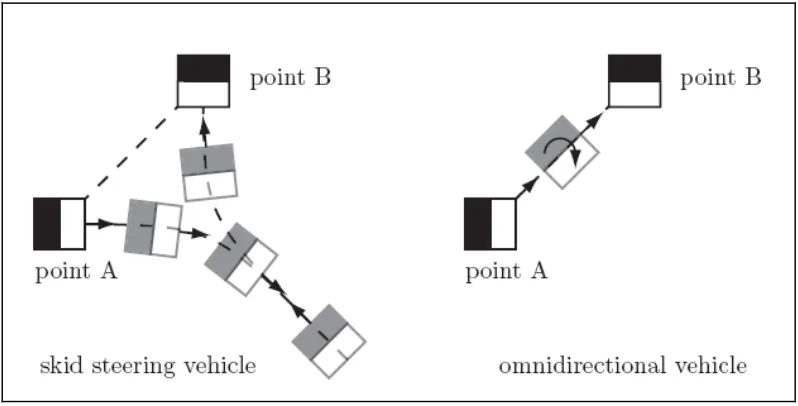
1.1 Non-holonomic mobility versus omni-directional
mobility 2
1.2 Traditional Mecanum wheel design by Ilon (1975) 3
1.3 Force vectors generated by Mecanum wheel 3
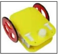
1.4 Castor wheeled robot 5
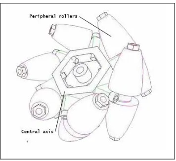
1.5 Mecanum wheel 7
1.6 Required wheel actuation for general movements 8
1.7 Rotational slip during wheel rotation 9
1.8 Front outline in 3D view 10
1.9 Exploded view 11
1.10 1.11 Roller shape: cylinder sectioned by a plane and resulted shape Wheel parameter 11
2.1 Flow chart of Methodology 16
2.2 Design of Mecanum wheel drawn on SolidWorks 2007 16
2.3 Mecanum wheel components 18
2.4 Mechanical structure 19
2.5 Electrical assembly 20
2.6 Motor configuration for program development 21
2.7 Program flowchart 22
2.8 Test run on game field 24
3.1 Active castor wheel 26
3.2 Steered wheel 26
3.3 Planar motion and 3 degree of freedom 30
xii
FIGURE TITLE PAGE
3.5 Mecanum wheel 31
3.6 Orthogonal wheel 32
3.7 Two-wheel differential drive system 33
3.8 Two-wheel differential drive system 34
3.9 Three omni-directional wheel drive system 35
3.10 Four omni-directional wheel redundant system 35
3.11 Four Mecanum wheels drive system 36
3.12 Mobile robot notation 37
3.13 Differential drive vector 38
3.14 Holomonic drive vector 40
3.15 Mecanum drive vector 40
4.1 Side and top view of Mecanum wheel 41
4.2 Faulty passive rollers 42
4.3 Improved passive rollers 43
4.4 Force vector for right sliding drive 44
4.5 Two sets of Mecanum wheels with different roller 45
4.6 Robot base design 46
4.8 Testing result plotted on graph 48
xii
LIST OF ABBREVIATIONS
IFC - Interface Free Controller
ICR - Instantaneous Center of Rotation
DC - Direct Current
CCW - Counter Clock Wise
CW - Clockwise
xii
LIST OF APPENDICES
APPENDIX TITLE PAGE
A Mecanum wheel drawing 54
1
CHAPTER 1
INTRODUCTION AND LITERATURE REVIEW
1.1Introduction
Multidirectional robot movement with real-time control interface has become an
integral part of a modern robotic technology. Several designs of modern and technically
enhanced wheels has been found and developed to improve the movements of robots and
other robotic machines for industry appliances and commercial use. The designs of
omni-directional vehicles have been proposed and the approaches divided into two classes as such
the conventional wheel designs and special wheel designs.
The conventional wheels are mechanically simple, have high load capacity and high
tolerance to work surface irregularities. Nevertheless, due to their non-holonomic nature
(Fig 1.1), they are truly omni-directional. Designs have been proposed to achieve near
omni-directional mobility using conventional wheels. The most common one is the steered
wheels. They can move in any direction from any configuration but it is not a truly
omni-directional because it need to stop and re-orient wheels to the desired direction whenever it
need to travel in a trajectory with non-continuous curvatures. Special wheels designs are
based on a concept that achieves traction in one direction and allow passive motion in
another, thus allowing greater flexibility in congested environments. One of such wheel
2
Figure 1.1: Non-holonomic mobility versus omni-directional mobility
This project employs a multidirectional actuating wheel name by Mecanum or
Swedish wheel to develop a multidirectional manual mobile robot. The Mecanum wheel
was invented in 1973 by a Swedish engineer (Mecanum Company), named Ilon (Ilon,
1975). This is why it is called Mecanum or Swedish wheel.
Mecanum wheel is based on the principle of a central wheel with a number of rollers
placed at an angle around the periphery of the wheel. The angled peripheral roller translates
a portion of the force in the rotational direction of the wheel to force normal to the wheel
directional. Depending on each individual wheel direction and speed, the resulting
combination of all these forces produces a total force vector in any desired direction hence
allowing the platform to move freely in direction of resulting force vector, without
changing the direction of the wheel. Figure 1.2 shows a traditional Mecanum wheel design
by Ilon with the peripheral roller with 45° degree slope held in place from the outside. The
concept is by using four mecanum wheels to provide omnidirectional movement for a
vehicle without needing a conventional steering system.
Due to the dynamics of the mecanum wheel, it can create force vectors in both the x
[image:18.612.107.506.81.284.2]3
in the y-direction. Positioning four Mecanum wheels, one at each corner of the robot base
(two mirrored pairs), allows mesh forces to be formed in the x, y and rotational direction
(Fig. 1.3). A difficulty with this strategy is that there are four variables to control three
degrees-of-freedom. In this case the system is said to be over determined and it is possible
to create conflicts in the actuation. As a result of the constraints associated with the
Mecanum wheel some form of controller is required to produce satisfactory motion.
[image:19.612.176.437.226.377.2]Figure 1.2: Traditional Mecanum wheel design by Ilon (1975)
[image:19.612.216.399.425.594.2]4
1.2Objective
Omni-directional mobile robot drive has wide range of studies and development,
therefore the core idea of the project defined at initial stage of research and development.
Although there are variety of wheels and configuration applied to achieve omni-directional
mobility, this project emphasis multi-directional mobile robot using Mecanum wheel and
the objective to be attained as following:
a) To design and fabricate a suitable Mecannum wheel for a mobile robot drive that
could enhance omni-directional mobility.
b) To arrange the wheels in a suitable configuration for the mobile robot drive to
achieve an efficient omni-directional movement
c) To achieve multi directional motion using the wheels arrangements on the robot
base with appropriate mounting method.
d) To select required multidirectional motions for manual robot based on the Robocon
environment. Commonly X-axis and Y-axis motion.
e) To implement joystick control for the multidirectional robot drive as input to the
microprocessor to synergize with the program created to control the wheels
independently.
1.3Scope
The project scaled to accomplish specific requirement based on the project
objective. This does employ certain project development proficiency to ensure the result
achieved within the scope defined. Therefore, clear pictures of the project requirements
need to be comprehended. The following are the scope of the project;
a) Research, Design & Develop the most appropriate & efficient mecanum wheel for a
5
on types of Mecanum wheel design available and choose the most suitable type that
can be fabricated yet applicable. The design for the wheels primarily focused to the
ease to fabricate and efficient, low cost as well. Development process of the wheel
entirely involves mechanical process and conducted with conventional machines.
b) Configure the mechanism of Mecanum wheel with driver to obtain the desired
omni-directional motion. Each of the wheels required to be controlled independently
because of the wheel mechanism as such to obtain omni-directional movements as
desired combining the microcontroller and joystick to make up the system.
1.4 Problem Statement
Robots using conventional wheels such as steered / castor wheels, (Fig. 1.4) are
inherently simple but the circumstances are it has high load capacity and high tolerance to
[image:21.612.260.355.432.520.2]floor irregularities such as bumps, cracks, dirt and debris.
Figure 1.4: Castor wheeled robot
Mobile robots based on this design have at least two active wheels, each of which
has both driving and steering actuators. They can move in any direction from any
configuration. However, this type of system is not truly omni-directional because it needs to
stop and re-orient its wheels to the desired direction whenever it needs to travel in a
6
One major drawback of conventional wheel designs is the high friction and
scrubbing during the steering as the wheel is actively twisted around a vertical axis. This
reduces positioning accuracy and increases power consumption and tire wear. The
fundamental cause of the scrubbing problem is that the wheel generates larger frictional
forces when steered actively around a vertical axis than when it is rolling.
Besides of those stated circumstances, to control the conventional wheeled robots is
complicated in a situation where it is required to achieve a target destination in most
accurate position and high acceleration. This is the basic requirement that a mobile robot
must have where it’s one of the specification required for a Robot competition. In a state of
time constrain, robot having a castor wheeled or steered wheeled difficult to achieve
acceleration by remaining desired accuracy at the same instants.
1.5 Literature Review
1.5.1 Review 1
a) Title: Improved Mecanum Wheel Design for Omni-directional Robot
b) Author: Olaf Diegal,Glen Bright & Johan Potgieter
c) Institution: Massey University, Aukland
d) Description: The efficiency of Mecanum wheel can be improved mechanically by
improving the energy losses during traveling & the peripheral rollers have the
capabilities of having its angles dynamically adjusted to best suit the direction the
platform is traveling. The efficiency explained as the technical performance that could
be improved from modification in the core elements of the Mecanum wheel.
e) Review outcome: There are three main elements in this wheel that affects its
performance that is:
i.Angle of peripheral rollers on central wheel
7
iii.Design of peripheral rollers
Based on the contents of this literature, it is learned that there are possibilities to
improve the performance of the wheel by varying the main elements of the wheel.
Therefore, the design of the Mecanum wheel should consider all three the elements of the
wheel.
[image:23.612.219.397.224.387.2]
Figure 1.5: Mecanum wheel
1.5.2 Review 2
a) Title: Designing Omni-Directional Mobile Robot with Mecanum Wheel
b) Author: Jefri Efendi Mohd Salih, Mohamed Rizon, Sazali Yaacob
c) Institution: Terengganu Advanced Technical Institute, Malaysia
d) Description: Design and development of an omni-directional platform, using
mechatronics system and Mecanum wheels creates intelligent behaviours and
maneuvers. With the combination of a microcontroller interfaced with sensors the robot
could achieve extreme maneuverability in congested environment. The combination of
mechanical design on the wheel and chassis, motion control and multiple input/output
sensors allow the exploration of large number of control algorithm and software to be
8
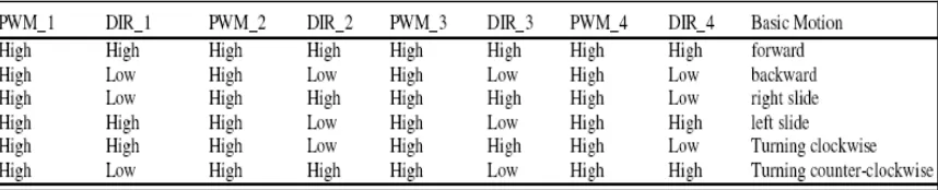
[image:24.612.154.466.102.250.2]Figure 1.6: Required wheel actuation for general movements
Table 1.1: Motor control for basic motion
e) Review outcome: The literature explains that the Mecanum wheel could be used when an
appropriate combination of mechatronic systems applied to the robot platform. This
describes that when the synergized systems applied for the desired robots it depicts the
intelligence behavior of the robot. Intelligent in this term can be explained as the robot
capable to move to any direction from any configuration with a simple control. To
achieve truly omni-directional movements using the Mecanum wheel, it requires an
accurate motor drive whereby the system entirely depends on the rotation direction and
speed of the driver motor. Furthermore, intelligent criteria for the robot be able to
[image:24.612.89.518.330.417.2]