EFFECT OF DBD PLASMA ACTUATOR AT THE MIDDLE SPAN OF AIRFOIL
QASEM AHMED QASEM AL-AREQI
A report submitted
in fulfilment of the requirements for the degree of Bachelor of Mechanical Engineering
Faculty of Mechanical Engineering
UNIVERSITI TEKNIKAL MALAYSIA MELAKA 8
APPROVAL
I hereby declare that I have read this project report and in my opinion this report is sufficient in
terms of scope and quality for the award of the degree of Bachelor of Mechanical Engineering
(with Honors)
Signature : ...
Name of Supervisor : Dr. Nazri Bin Md Daud
DECLARATION
I declare that this project report entitled “Effect of DBD Plasma Actuator At The Middle Span Of Airfoil” is the result of my own work except as cited in the references.
Signature : ...
Name : Qasem Ahmed Qasem AL-Areqi
DEDICATION
I would like to dedicate this humble effort to
Those who care about me when I need support and motivation
My father
AHMED QASEM ALI To whom I miss, my late mother
To my supporting
Family
To whom give me much of his time and knowledge
My supervisor,
DR. NAZRI BIN MD DAUD To my lovely country
YEMEN To my second home
MALAYSIA and
To all my friend,
i
ABSTRACT
ii
ACKNOWLEDGEMENT
In the beginning, I would like to express my full gratitude to Allah for granting
me the best condition of health and strength in completing my final year project. My
deepest thanks to DR. NAZRI BIN MD DAUD for his time, guidance and support,
and for his unfaltering professionalism and devotion in his activities both as an
academic and as a supervisor in these two semesters. Respectfully, very special
appreciation to all technicians in the Labs of Mechanical Engineering, and all the staff
in charge in UTeM facilities for giving me full assistance and additional knowledge in
helping me to complete my research. Besides, I offer all thanks and appreciation to all
my friends for their support. Last but not least I can only express my gratitude and
thanks to my lovely family father, brothers, sisters, cousins for their help, support,
motivation to achieve my goal. Finally, appreciation to Universiti Teknikal Malaysia
Melaka for giving me the chance to complete my undergraduate program and gaining a
iii
TABLE OF CONTENTS
CHAPTER CONTENT PAGE
DECLARATION APPROVAL DEDICATION
ABSTRACT i
ACKNOWLEDGEMENT ii
TABLE OF CONTENTS iii
LIST OF TABLES vi
LIST OF FIGURES vii
LIST OF SYMBOLS ix
CHAPTER 1 INTRODUCTION 1
1.1 Overview 1
1.2 Background 1
1.3 Problem Statement 4
1.4 Objective 5
1.5 Scope of Project 5
CHAPTER 2 LITERATURE REVIEW 6
2.1 overview 6
2.2 Basic Principle of Plasma 6
2.3 Separation Control 7
iv
2.5 Simulation 8
2.5.1 Effect of DBD Plasma on NACA 0021 8
2.5.2 Effect of DBD plasma on NACA4415.
9
2.6 Experiment 11
2.6.1 Control The Flow Separation With 11
Barrier Plasma Actuators 2.6.2 Effect Of DBD Plasma On NACA 0015 13
2.6.3 Compare The Lift Coefficient During 14
Plasma ON And Plasma OFF
2.7 Generate Light Emission Time Series 16
CHAPTER 3 METHODOLOGY 18
3.1 Overview 18
3.2 Experimental Flow Chart 18
3.3 Experiment set up 21
3.3.1 Wind Tunnel 21
3.3.2 Airfoil Type 22
3.3.3 DBD Plasma Actuator 23
3.4 Measuring the Lift Force 25
3.5 Experiment Condition 26
3.6 Procedure to Install DBD Plasma 27
CHAPTER 4 RESULT AND DISCUSSION 31
4.1 Overview 31
4.2 Experiment Without Using DBD Plasma 31
Actuator
4.3 Experiment with Using DBD Plasma Actuator 36
4.4 Compare the Lift Coefficient and Drag 39
v
CHAPTER 5 CONCLUSION AND RECOMMENDATION 42
5.1 Conclusion 42
5.2 Recommendation 43
REFERENCE 44
vi
LIST OF TABLES
TABLE TITLE
PAGE 2.1 Differences of CL values between plasma OFF and
plasma ON for (a) Re = 3.2 × 10⁵ and (b) Re =3.6 × 10⁵ 15
3.1 List of content 27
4.1 Lift coefficient and drag coefficient when plasma OFF 34 4.2 Lift coefficient and drag coefficient when plasma ON 37 4.3 Compare the lift coefficient between (plasma ON and
plasma OFF) 40
4.4 Compare the drag coefficient between (plasma ON
and plasma OFF) 41
vii
FIGURE TITLE PAGE
1.1 Configuration of SDBD plasma actuator 4
1.2 Flow separation at different angles of airfoil 5
2.1 Plasma actuator on the flat plate 8
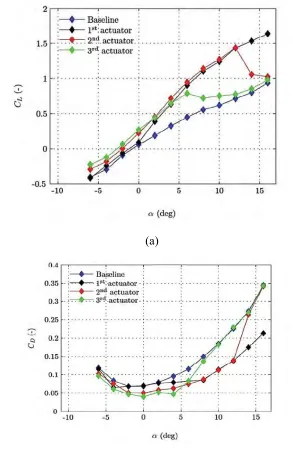
2.2 Variation of Lift coefficient and Drag coefficient at different
angle of attack at 1𝑠𝑡, 2𝑛𝑑𝑎𝑛𝑑 3𝑛𝑑 actuators: (a) 𝐶
𝐿; (b) 𝐶𝐷.
10
2.3 The effect of DBD plasma on airfoil and circular cylinder 12
2.4 Effect of plasma induced around NACA0015 airfoil at =
10and Re = 30000
14
2.5 The time series of photomultiplier tube (PMT) output (a) , a
sample of voltage time series for two and a half cycles of plasma actuator (b)
16
2.6 The forward stroke of individual microischarge (a) and the
back stroke of individual microischarge (b)
17
3.1 Flow chart of the project 20
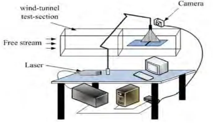
3.2 Wind tunnel Schematic diagram 21
3.3 The dimensions of the airfoil 22
3.4 End plates of the wing 22
3.5 Location of the DBD plasma actutor 23
3.6 Schematic diagram of DBD plasma actuator with dimensions 24
3.7 The movement of ions during actuation of DBD plasma 25
viii
3.9 Put the copper film on the middle of the 28
3.10 Cover the copper by another piece of Kapton film 29
3.11 Place another copper film and put gap between the two coppers 29
3.12 Connect the power supply to the two coppers 30
3.13 Actuator top view, as mounted on the test stand 30
4.1 Flow separation at angle of attack 8° 33
4.2 Lift coefficient vs angle of attack, standard NACA 0015 airfoil
with plasma OFF
35
4.3 Drag coefficient vs angle of attack, standard NACA 0015 airfoil
with plasma OFF
35
4.4 Lift coefficient vs angle of attack, standard NACA 0015 airfoil
with plasma ON
38
4.5 Drag coefficient vs angle of attack, standard NACA 0015 airfoil
with plasma ON
38
4.6 Compare the lift coefficient during (plasma ON and OFF) 40
ix
LIST OF SYMBOLS
CD Drag coefficient
CL Lift coefficient
D Drag force L Lift force
Re Reynolds number
Vpeak−peak Base voltage peak to peak
1
CHAPTER 1
INTRODUCTION
1.1 Overview
This chapter, will a brief introduction the background is introduced which contain of background information about effect of Dielectric Barrier Discharge (DBD) on airfoil, problem statement, objective and the scopes of the research.
1.2 Background
2
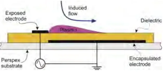
Dielectric Barrier Discharge (DBD) plasma actuators It's a new technique. It
becomes the common device in the application of control natural flow that has been studied its purpose to solve problems flow control as an airfoil or circular cylinder also flat plate. it can be modified or interruption of periodic DBD plasma actuators, use a high voltage AC waveform to produce plasma in the area between the electrodes by input signal this device used commonly, the plasma ions quickened by electric field and conflict with molecules of atmosphere, the average time of flow from uncovered electrode to the insulated electrode is induced. Momentum is transmitted from plasma discharge to the surrounding air through a conflict between ions which produce body force. The Electrochemical reaction the air-plasma plasma causes plasma motility due to low current density Electrons, negative and positive ions and neutral particle (Wang et al., 2007; Singh and Gaitonde, 2006). In a classic way when the air ionized is called plasma that is why this term Plasma is used for DBD plasma actuator (Cavalieri, 1995; Corke and Matlis, 2000; Corke et al., 2001). The ionized air it shows as blue color due to the air recombines and de-excite to ionized components (Davidson and O'Neil, 1964).
The initial model of DBD plasma actuator was created by Massines et al. (1998). The mode at that time was based one Poisson equation and simultaneous solution to produce 1D mode. (1999) created 2D reproduction to consider the time-subordinate advancement and the electrical field of particles amid a high-voltage beat. The reproduction uncovered that the charged particles exchanged to the high electric potential district and made a high-electric field quality close to the anode's edges. It additionally demonstrated that the plasma developed on a brief period in microsecond timescale.
3
Shyy et al. (2002) assume that the electric field is quality diminished straightly from the edge of the uncovered terminal to the dielectric-covered electrode. But the result of Shyy et al (2002) was not reliable with the discoveries from Enloe et al.(2004b); Orlov (2006); Orlov et al. (2006). in (2008) Singh and Roy us the results a first-principle reproduction and experimental perceptions from claiming actuator conduct technique to developed 2D body-force components.
Sato et al. (2013) and Nonomura et al. (2013) have led the numerical examination of the isolated stream over an airfoil. Both from claiming them connected large-eddy Recreation (LES) on the divided stream which controlled by An DBD plasma actuator. Sato et al. (2013) found that the vast majority powerful blast recurrence of blast wave might have been 500 Hz. From the straightforward examination for turbulent dynamic vitality distribution, they advocated that those situations for fast turbulent move in airfoil would do well to air motion facilitating execution. Nonomura et al. (2013) concentrated on the stream control component to control the partition bubble. They got that the body of evidence for nondimensional blast wave for 600 Hz required prior What's more smooth birch move. This may be a direct result those incitation for nondimensional blast wave for 600 Hz successfully excites the Kelvin-Helmholz precariousness.
4
[image:17.612.160.473.174.312.2]Generally, those vital Characteristics viewing those DBD plasma actuator are those build frequency, voltage, energy consumption, geometry of the actuator, and the speed processed by those produced plasma. Seeing these features are extremely critical to those following phases about further research.
Fig. 1.1 Configuration of SDBD plasma actuator
1.3Problem Statement
5
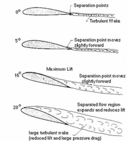
Fig. 1.2: Flow separation at different angles of airfoil
1.4 Objective
To compare the aerodynamic performance of airfoil between base case and actuation case.
1.5Scope of Project
In this research the scope will be:
1- Model airfoil NACA 0015.
2- DBD plasma actuator at power 6KV and frequency at 8KHz.
6
CHAPTER 2
LITERATURE REVIEW
2.1 Overview
In this chapter will discuss about the literature review related to the effect of the DBD plasma actuator on the airfoil. Also, the fundamental of the techniques will be discussed in detail such as the concept principle of plasma, separation control and utilization of DBD plasma to control the flow separation.
2.2Basic Principle of Plasma.
7
In an atmospheric plasma, it may be utilized an assortment of energy supplies from DC to RF. The challenge may be how to design electrodes and gas flux to produce intimate connection among the substrate and interaction gases. While the gas conflict between each other, the molecules and atoms are consumed very fast in high pressure, so the time that need a plasma to transport into the surface must be short. Must be taken precaution and cautiously prevent curvature the electrodes to get operation with low temperature in atmospheric plasmas.
2.3Separation Control
At the recent years the researchers have been developing the flow separation system due to lead to geometric changes such as slotted LE slats and TE flaps that functioned in many operational of aircraft. The PFC has slotted potions working to energizing the boundary layer at the surface section by mixing the momentum fluid from the pressure surface allowing it to follow the curvature of the deflected system. The is difficult and complex to reducing or elimination the flow separation during takeoff and landing at low or high lift.
Background information focuses on control the flow separation by the studies that have been containing at two-dimensional actuation on two-dimensional airfoil models. It must be taken into account parameters and the values such as frequency favourably from 2D airfoil to 3Dscale and angle of airfoil (Seifert and Tillman 2009).
2.4 Effect of DBD plasma on flat plate
8
[image:21.612.148.491.272.471.2]used 5.5KHz sine wave AC signal. The result shows the thickness of boundary layer is decrease at the edge of the flat plate and the local rise near well velocity by effective the DBD plasma actuator. The actuator generated reproduction the energy exchange between the boundary layer and the flow, which add dynamic energy to fluid by actuator. When the velocity increases the energy of the dynamic is loss so need to add energy to the actuator. Its mean the DBD plasma actuator is better performance at lower free-steam velocity.
Fig. 2.1 Plasma actuator on the flat plate
2.5Simulation
2.5.1 Effect of DBD Plasma on NACA 0021
9
0.3m and the second was0.25m with span was 0.6m, both tested at the same wind tunnel of airfoil with section 0.6 ×1.1m. Various velocity of steam that have been tested at 5-15 m/s and Reynolds numbers among 0.8× 10⁵ and 3× 10⁵.
Measure the drag coefficient that obtain from separation of flow over the airfoil skin by wake survey, also tested at different angle of attack from 4° to 20° and flap deflection at 0° and 15° deg. The data presented at two locations first set up the actuator at 5% of chord length and second placed upstream of the flap brink at chord length about 75%. Measurement was perfect for the momentum that input to the single dialectic barrier discharge plasma actuators (SDBD). So, investigate at
Reynolds number more than 1× 10⁵ the separation occurs because the momentum
is not sufficient it has low effect to reduce the separation, because the Reynolds number is very high so need to work at low velocity. At low Reynolds number is more effective in micro air vehicles, the plasma provides more momentum to delay the separation.
2.5.2 Effect of DBD plasma on NACA 4415.
Study the effect of Dielectric Barrier Discharge (DBD) plasma actuator to NACA 4415 airfoil that generate lift and drag coefficients when the flow moves around airfoil by using measurement force balance, it shows at the different location of chord length at 30% and 60%. The airfoil was made by Plexiglas with length 100mm and width 158mm.every actuator is independently from each other between the positions and the voltage of pack to pack was 15.5KV and the frequency of 5KHz during lift generation. Test run at Re= 35000 along 100mm, velocity of 5 m/s and the angle of attack among -6° to 16°.
10
line), 2𝑛𝑑 at 30% (red line) and 3𝑟𝑑 at 60% (green line).The baseline condition is the blue line when the actuators are run, the 3𝑟𝑑 actuator (green line) have the highest lift coefficient at −6° more than baseline rate by 44%, however the 1𝑠𝑡 actuator the perfect lift coefficient at 16° is greater than baseline value by 75.7%.
(a)
[image:23.612.154.447.185.636.2](b)
11
2.6 Experiment
2.6.1 Control the Flow Separation with Dielectric Barrier Plasma Actuators
DBD plasma actuator it had been used in many devices to control the flow separation (Roth et al. 2000; Post and Corke 2004). In generally separate of flow from solid surface ((Telionis, 1979). As known, the detachment of fluid always leads to decrease the lift force and increase the drag force in addition losses of pressure recovery. DBD plasma applied for circular cylinder, airfoil and flat plate to study flow control separation (Y.E. Akansu et al., 2013; Hürrem Akbıyık et al., 2016; YU Jianyang et al., 2014). In this study will focus the effect of DBD plasma on airfoil and measure the lift and drag force. It has been reported lowest energy input than can cause control flow separation by Asada et al. (2009). Also, conduct burst wave use DBD plasma as experiment inside wind tunnel at low speed by Asada et al. (2009). Rethmel et al. (2011) the improvement and utilization of dielectric barrier discharge (DBD) plasma actuators that generate by nanosecond pulses in high Reynolds number aerodynamic flow control. Y.E. Akansu. (2013) investigated the manipulation of flow separation on NACA 0015 airfoil by the effect of DBD plasma actuator. Amitay, and Glezer. (2002) study the effect of actuation frequency for contact the flow over stalled airfoil. Asada et al. (2009) Abut small burst ratio it can caused strong separation control by used low power consumption. Rethmel et al. (2011) investigated the DBD plasma actuator with nanosecond pulse is not stable at high angle of attack and high velocity of airflow. As a result, the device is transfer momentum from the steam to the separated region by create coherent spanwise vortices, this is helping to airflow to pass upper the wing surface.