i
UNIVERSITI TEKNIKAL MALAYSIA MELAKA
OPTIMIZATION PERFORMANCE OF FIBER OPTIC SENSOR
ON FULLY SYNTHETIC TEST OIL FOR ENGINE
TRADITIONALLY PURPOSE
This report submitted in accordance with requirement of the Universiti Teknikal Malaysia Melaka (UTeM) for the Bachelor Degree of Electronic Engineering
Technology
(Telecommunication) (Honours.)
By
MOHAMAD ASSIF BIN ARIFFIN @ MOHD SAUFI
B071310575
940109-03-6147
FACULTY OF ENGINEERING TECHNOLOGY
ii
UNIVERSITI TEKNIKAL MALAYSIA MELAKA
BORANG PENGESAHAN STATUS LAPORAN PROJEK SARJANA MUDA
TAJUK: Optimization Performance of Fiber Optic Sensor Fully Synthetic Test Oil for Engine Traditionally Purpose
SESI PENGAJIAN: 2016/17 Semester 1
Saya MOHAMAD ASSIF BIN ARIFFIN @ MOHD SAUFI
mengaku membenarkan Laporan PSM ini disimpan di Perpustakaan Universiti Teknikal Malaysia Melaka (UTeM) dengan syarat-syarat kegunaan seperti berikut:
1. Laporan PSM adalah hak milik Universiti Teknikal Malaysia Melaka dan penulis. 2. Perpustakaan Universiti Teknikal Malaysia Melaka dibenarkan membuat salinan untuk
tujuan pengajian sahaja dengan izin penulis.
3. Perpustakaan dibenarkan membuat salinan laporan PSM ini sebagai bahan pertukaran antara institusi pengajian tinggi.
4. **Sila tandakan ( )
SULIT
TERHAD
TIDAK TERHAD
(Mengandungi maklumat yang berdarjah keselamatan atau kepentingan Malaysia sebagaimana yang termaktub dalam AKTA RAHSIA RASMI 1972)
(Mengandungi maklumat TERHAD yang telah ditentukan oleh organisasi/badan di mana penyelidikan dijalankan)
Alamat Tetap:
Kampung Lubuk Bunut ,Perol
16010 Kota Bharu,Kelantan
Tarikh: ________________________
Disahkan oleh:
Cop Rasmi:
Tarikh: _______________________
iii
DECLARATION
I hereby, declared this report entitle
Optimization Performance of Fiber Optic Sensor Fully Synthetic Test Oil for Engine Traditionally Purpose
Signature : ……….
Author’s Name : MOHAMAD ASSIF BIN ARIFFIN @ MOHD SAUFI
iv
APPROVAL
This report is submitted to the Faculty of Engineering Technology of UTeM as a partial fulfilment of the requirements for the degree of Bachelor of Electronic
Engineering Technology (Telecommunication) (Hons). The member of the supervisory us as follow:
……….
v
ABSTRAK
vi
ABSTRACT
vii
DEDICATION
Specially dedicated to,
viii
ACKNOWLEDGEMENT
First and foremost, I would like to express my greatest gratitude to my project supervisor, Associate Mrs. Aminah Binti Ahmad, for all the great supervision, supports, advises and guidance that help me lots with my final year project. His valuable advice is really useful for me.
Besides, I wish to express my profound gratitude to Md Ashadi Bin Md Johari, the co-supervisor for my research for his good cooperation. He has allowed me to obtain the knowledge about fiber optic sensor and I’ve taken lots of advice from he. I will never forget his kindness.
I also wish to thank the Laboratory Technicians, En Izwan Bin Hamdan that help me lots in preparing the suitable equipment for conducting the test. They also help me lots while collecting sample in the field. With their help, my works become easier. Thanks to both of you!
Not forget to thanks all of the postgraduate students for their help, cares and advice who have given me useful guidance on writing the thesis.
For my parents, you are the best “things” that I have. I don’t know what is the best word to describe your patience, love and cares towards me. Thanks for your moral support and encouragement.
ix
TABLE OF CONTENT
DECLARATION ... iii
APPROVAL ... iv
ABSTRAK ... v
ABSTRACT ... vi
DEDICATION ... vii
ACKNOWLEDGEMENT ... viii
TABLE OF CONTENT ... ix
LIST OF FIGURE ... xii
LIST OF TABLE ... xiv
LIST OF SYMBOL AND ABREVIATION ... xv
CHAPTER 1 ... 1
Introduction ... 1
Project Background ... 1
Problems Statement ... 3
Project Objectives ... 3
Project Scope ... 4
Summary ... 4
CHAPTER 2. ... 5
INTRODUCTION ... 5
Fiber optic ... 5
2.2.1 Basic Fiber Optic Communication System ... 5
2.2.2 Basic Fiber Optic... 6
Optical Fiber Basics ... 8
x
2.4.1 Single-Mode Step-Index Fiber ... 10
2.4.2 Multimode Step-Index Fiber ... 11
2.4.3 Multimode Graded-Index Fiber ... 11
Fiber Optic Sensor ... 12
2.5.1 Fiber Optic Sensor Principles... 12
2.5.2 Polarization Modulated Fiber Optic Sensors ... 14
2.5.3 Applications of Fiber Optic Sensors ... 15
Light Source used in Fiber Optic ... 16
Lubricant Oil ... 18
2.7.1 Properties of Lubricants ... 20
2.7.2 The viscosity of the lubricant ... 22
2.7.3 Fully synthetic Oil ... 23
Design of experiment ... 23
2.8.1 Random design ... 24
2.8.2 Orthogonal design ... 24
2.8.3 Factorial design ... 25
2.8.4 𝟐𝒌 Factorial Design ... 26
CHAPTER 3. ... 28
Introduction ... 28
Identify the Problem ... 28
Project Planning ... 29
Project Flow chart ... 31
3.4.1 Title Finding ... 31
3.4.2 Literature Review ... 32
3.4.3 Raw Material ... 32
3.4.4 Build Sensor ... 36
xi
3.4.6 Analyze Result ... 38
3.4.7 Writing Formal Report ... 40
CHAPTER 4. ... 41
Project Overview ... 41
Optical Fiber Sensor Diagram ... 41
Fiber Optic Fully Syntetic Sensor Data Collection ... 43
Analysis of Design Expert Result ... 45
4.4.1 Analysis of Half –Normal Plot ... 45
4.4.2 Analysis of Normal Plot ... 46
4.4.3 Analysis of Variance(ANOVA) ... 47
4.4.4 Analysis of Normal Plot Residuals ... 48
4.4.5 Analysis of Residual Vs Predicted ... 49
4.4.6 Analysis of Residual Vs Run ... 50
4.4.7 Analysis of Factor Interaction of Type of Fiber... 51
4.4.8 Analysis of Factor Interaction of light source ... 52
4.4.9 Analysis of concentration and Light source ... 53
4.4.10 Optimization Design ... 54
CHAPTER 5. ... 57
Conclusion ... 57
Recommendation ... 58
REFERENCE ... 59
xii
LIST OF FIGURE
Figure 2.1 Basic fiber optic communication system ... 6
Figure 2.2: Simple Fiber Optic Link ... 6
Figure 2.3:Basic structure of an optical fiber ... 9
Figure 2.4:Different types of optical fibers. ... 10
Figure 2.5:Single-Mode Step-Index Fiber ... 10
Figure 2.6:Multimode Step-Index Fiber ... 11
Figure 2.7:Multimode Graded-Index Fiber ... 11
Figure 2.8:Basic components of an optical fiber sensor system.. ... 13
Figure 2.9:Extrinsic and intrinsic types of fiber optic sensors.. ... 13
Figure 2.10:Polarization-based Fiber Optic Sensor ... 15
Figure 2.11:Surface emitting and Edge emitting ... 16
Figure 2.12:Output Power Vs Drive current ... 17
Figure 2.13:Random Design ... 24
Figure 2.14:Orthogonal Design ... 25
Figure 2.15:The 23 design (Montgomery, 2013) Geometric view, design matrix and table. ... 27
Figure 2.16:The algebraic sign for calculating effects in the 23 design (Montgomery,2013). ... 27
Figure 3.1:Development of Fiber Optic Sensor Flow Chart ... 30
Figure 3.2:Step of Project Flow chart ... 31
Figure 3.3:Splicing Machine and Fusion State ... 33
Figure 3.4:Optical Spectrum analyser ... 34
Figure 3.5:Amplified Spontaneous Emission ... 34
Figure 3.6:Pigtail Cable ... 35
Figure 3.7:Survey of the collecting data on fully synthetic oil ... 35
Figure 3.8:Tool Box ... 36
Figure 3.9:Stripping The Cladding of Fiber ... 37
Figure 3.10:Cleaving The Core of the Fiber ... 37
xiii
Figure 3.12:Fully Synthetic Test Area ... 38
Figure 4.1:single mode optical fiber sensor for fully synthetic ... 42
Figure 4.2:multi-mode optical fiber sensor for fully synthetic ... 43
Figure 4.3:Graph of Run Vs Power ... 44
Figure 4.4:Graph normal plot ... 46
Figure 4.5:Graph Normal Plot... 47
Figure 4.6:Value for the Graph(ANOVA) ... 48
Figure 4.7:Graph Normal Plot of Residuals ... 49
Figure 4.8:Graph Normal Plot of Residuals ... 50
Figure 4.9:Graph Residuals vs Run ... 51
Figure 4.10:One Factor Graph for Type of fiber... 52
Figure 4.11:One Factor Graph for Light Source. ... 53
xiv
LIST OF TABLE
Table 2.1:Comparison Light source ... 16
Table 3.1:Parameter of material ... 39
Table 3.2: Matrix Design of experiment ... 40
xv
LIST OF SYMBOL AND ABREVIATION
DOE = Design of Experiment
OFAT = One Factor at a Time Method TQM = Total Quality Management TPM = Target Performance Measure NPM = Noise Performance Measure LED = Light Emitting Diode FFD = Full Factorial Design MMF = Multi-Mode Strands SMF = Single-Mode Strands PCS = Plastic-Clad Silica
ASE = Amplified Spontaneous Emission OSA = Optical Spectrum Analyzer ANOVA = Analysis of Variance
LRIS = Liquid Refractive Index Sensor SPR = Surface Plasmon Reverberation dB = Decibel
1
CHAPTER 1
INTRODUCTION
Introduction
This chapter is covered some topics. There are many lubricant oil can be used of engine oil such as fully synthetic oil, semi synthetic oil and mineral oil. This project focus on the fully synthetic oil that need to be solved during experiment by using detection sensor of fiber optic. The project explain about how the study was conducted included the background of project’s title, the objective, Problem statement faced of this project, work scopes, project significant and finally project’s summary.
Project Background
2 changing fibre so that quantity that want to measure by modulated intensity, phase, polarization, wavelength or transit light time in fiber. Sensor that different light power is that simplest, because only one basic resources and indicator required
3
Problems Statement
Many vehicle users have a problem to determine where the concentration of oil that can be adopted if do not have any better sign.They often depends on the date notified by the mechanic.For example, there are a lot of lubricant oil that can be used of engine oil is mineral oil, semi synthetic oil and fully synthetic oil.So this project use for fully synthetic oil to conduct of this research.Therefore it can be used for highest levels of performance and an important substance for many modern engines. Moreover, user do not know the condition of lubrication oil in engine Is good or bad. Other than that, to become again problem of this project can fiber optic become as a sensor to detect lubricant oil? So, one of fiber optic senser could be developed to detect the performance of lubricant oil which is used according to the levels of energy whether it is good, less good and very concentrated.Due to that,the lubricant oil should be changed every few kilometers away.Each lubricant oil concentration is have own result of the concentration.Furthermore,with the fiber optic sensor can help users to solve problems that depend only on the date and notified by mechanic. Then, with a sample of fully synthetic oil experiment, experimental data can be applied as an indicator developed by fiber optic sensor.The lubricant engine oil has three type of engine oil is mineral oil, semi synthetic oil and fully synthetic oil. Engine oil is very important material to allow the engine to function more smoothly.So, one fiber optic sensor was developed to detect the thickness fully synthetic oil. By developing of this fiber optic sensor, it can be applied inside the engine to easy vehicle user.
Project Objectives
The step to make this project success related in study of Fiber Optic Sensor which are have three the main of project objectives. The objectives of this project are:
i. To study Fiber Optic Sensor(FOS)
ii. To develop Fiber Optic Sensor to detect the condition in fully synthetic oil iii. To analyze performance of Fiber Optic Sensor using design of
4
Project Scope
In order to complete the objective of the project, the scope have been listed which is related of the objective project. In BDP 1, study about project research on the concept of fiber optic sensor and need to study about the lubricant oil to be use as a parameter of the experiment. Besides literature review and methodology has been included which more related about the project research. Next, for PSM 2 will focus on experiment result, discussion on how project is carried out, analyze data and conclusion.
The scope of work in this project are given:
1. Understanding of fiber optic sensor 2. Fiber optic design to be used as a sensor.
3. Understanding the effects of the use of fully synthetic oil on fiber optic 4. Obtain the optimization for FOS in lubrication oil using Design of
experiment (DOE)
5. The result can be analyzed and studied.
Summary
5
CHAPTER 2.
LITERATURE REVIEW
INTRODUCTION
This chapter is about literature review that is related to this final year project. This part will explain about understanding on the fibre optic sensor, technique used in fibre optic sensor, design of the fibre optic sensor for lubricant oil concentration and optimization and design of experiment.
Fiber optic
2.2.1 Basic Fiber Optic Communication System
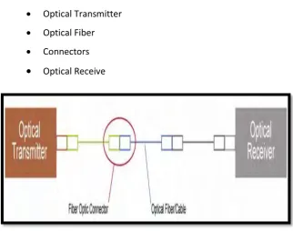
6 In the case to understand how fiber optic applications work, it is essential to comprehend the segments of a fiber optic connection. There are four fundamental parts in a fiber optic connection (Awad, 2012)
Optical Transmitter
Optical Fiber
[image:21.595.159.475.73.222.2] Connectors Optical Receive
Figure 2.2: Simple Fiber Optic Link
2.2.2 Basic Fiber Optic
[image:21.595.156.479.309.563.2]fiber optic basically glass piece adapt as thin as human hair used for telecommunication. This piece deliver digital signal with light. Although fact that this link made of glass, they are mild and not soft. They can crooked type of wire and very solid. When hundreds or thousands piece are arranged in pack,
7 it is called optic cable. Optic fiber cable is cable which contains a or over optic piece used to relay light. Fibre optic component that usually solely covered with plastic layer and which include in protection suitable fund for environment where cable will be used. like various cables used for various applications, long distance example telecommunication, or give information association that is quick between various section of the building. Glass cable mortgagees by running defence that is extraordinary called cladding. It is produced using material which reflects light again into core or cable centre. Ini cladding makes mirror line divisor. fibre optic work use internal reflection number of principles. At the moment when light disseminated into glass cable, light which rebounded from reflective cladding beside glass cable, so that light can move on around angle. In other word meaning, light which rebounded from inside cable until it reach his destination. There are more than part for fibre optic framework from cable. The main thing is that transmitter. It relays signs will over cable. Actually, light signal repeated and another with qualities that equally sent by regenerator. Finally, there is optic recipient. It obtains light signal and encode them into structure that is readable for tool to final direction.
8
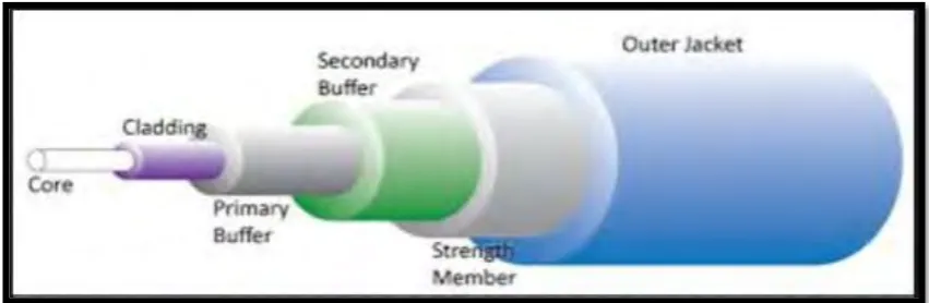
Optical Fiber Basics
An optical fiber is composed of three parts; the core, the cladding, and the coating or buffer. The basic structure is shown in Figure.
Core: This central area, made of silica or doped silica, is the light transmitting locale of the fiber. The core is a tube-shaped pole of dielectric material and is for the most part made of glass. Light propagates for the most part along the core of the fiber
Cladding: This is the principal layer around the core. It is additionally made of silica, however not the same structure as the core. This makes an optical waveguide which confines the light in the core by total internal reflection at the core-cladding interface. The cladding layer is made of a dielectric material with an index of refraction. The index of refraction of the cladding material is not as much as that of the core material. The cladding is by and large made of glass or plastic. The cladding executes such function as diminishing loss of light from core into the surrounding air, decreasing scattering loss at the surface of the core, protecting the fiber from absorbing the surface contaminants and adding mechanical strength.
Coating: The coating is the principal non-optical layer around the cladding. The coating normally comprises of one or more layers of polymer that secure the silica structure against physical or ecological harm. The coating is stripped off when the fiber is connectorized or fusion spliced. The coating or buffer is a layer of material used to shield an optical fiber from physical harm. The material utilized for a buffer is a sort of plastic.
Buffer: The buffer is an imperative component of the fiber. It is 900 microns and helps protect the fiber from breaking amid establishment and is situated outside of the coating. The buffer is elastic in nature and averts scraped areas.(Awad, 2012)
9 Outer Cable Jacket: This is external layer of any cable. The jacketed fiber is generally enclosed, with a bundle of flexible fibrous polymer strength members like aramid in a lightweight plastic spread to shape a straightforward cable. Every end of the cable might be ended with a particular optical
Type of Fiber Optic
[image:24.595.109.535.158.297.2]Single-mode and multi-mode are the two fundamental sorts of fiber optic cable. Single-mode fiber cable sends signals utilizing laser light. They are littler in thickness than multi-mode. A single-mode fiber has a little core that strengths the light waves to stay in the same way, or mode. This keeps the light signal going further before they should be beefed up, or amplified. Most long- distance, or long-haul, fiber optic phone lines use single-mode fiber. Multi-mode fibers send signals utilizing light-emitting diodes or LEDs. They are bigger in thickness or diameter than the single-mode cables. A multi-mode fiber has a much bigger core than single-mode fiber. This gives light waves more space to ricochet around inside as they go down the way. The additional development in the long run causes the beats to spread, and lose data. That implies multimode fiber signals can't go as far before they should be cleaned up and re-increased. Multimode fibers can carry only a third or less the information-carrying capacity or bandwidth than single-mode fiber. (such as in LANs) (Choi & Ph, 2014)