This is a repository copy of The contact mechanics and occurrence of edge loading in modular metal-on-polyethylene total hip replacement during daily activities.
White Rose Research Online URL for this paper: http://eprints.whiterose.ac.uk/98596/
Version: Accepted Version
Article:
Hua, X, Li, J, Jin, Z et al. (1 more author) (2016) The contact mechanics and occurrence of edge loading in modular metal-on-polyethylene total hip replacement during daily activities. Medical Engineering and Physics, 38 (6). pp. 518-525. ISSN 1350-4533
https://doi.org/10.1016/j.medengphy.2016.03.004
Crown Copyright © 2016. Published by Elsevier Ltd on behalf of IPEM. Licensed under the Creative Commons Attribution-NonCommercial-NoDerivatives 4.0 International
http://creativecommons.org/licenses/by-nc-nd/4.0/
[email protected] https://eprints.whiterose.ac.uk/
Reuse
Unless indicated otherwise, fulltext items are protected by copyright with all rights reserved. The copyright exception in section 29 of the Copyright, Designs and Patents Act 1988 allows the making of a single copy solely for the purpose of non-commercial research or private study within the limits of fair dealing. The publisher or other rights-holder may allow further reproduction and re-use of this version - refer to the White Rose Research Online record for this item. Where records identify the publisher as the copyright holder, users can verify any specific terms of use on the publisher’s website.
Takedown
If you consider content in White Rose Research Online to be in breach of UK law, please notify us by
1 1
2
The contact mechanics and occurrence of edge loading in modular
metal-on-3polyethylene total hip replacement during daily activities
45
Xijin Hua1, Junyan Li2, Zhongmin Jin1,3, John Fisher1
6
1 Institute of Medical and Biological Engineering, School of Mechanical Engineering, 7
University of Leeds, Leeds, UK
8
2 School of Science and Technology, Middlesex University, London, UK 9
3State Key Laboratory for Manufacturing System Engineering, Xi’an Jiaotong University,
10
Xi’an, PR China
11 12 13 14 15 16 17
Corresponding author:
18
Xijin Hua
19
Institute of Medical and Biological Engineering, School of Mechanical Engineering,
20
University of Leeds, Leeds, LS2 9JT, UK.
21
Email: [email protected]; [email protected]
22
23
Word count : 4628
2
Abstract: The occurrence of edge loading in hip joint replacement has been associated with 25
many factors such as prosthetic design, component malposition and activities of daily living.
26
The present study aimed to quantify the occurrence of edge loading/contact at the articulating
27
surface and to evaluate the effect of cup angles and edge loading on the contact mechanics of
28
a modular metal-on-polyethylene (MoP) total hip replacement (THR) during different daily
29
activities. A three-dimensional finite element model was developed based on a modular MoP
30
bearing system. Different cup inclination and anteversion angles were modelled and six daily
31
activities were considered. The results showed that edge loading was predicted during normal
32
walking, ascending and descending stairs activities under steep cup inclination conditions
33
(≥ 55°) while no edge loading was observed during standing up, sitting down and knee
34
bending activities. The duration of edge loading increased with increased cup inclination
35
angles and was affected by the cup anteversion angles. Edge loading caused elevated contact
36
pressure at the articulating surface and substantially increased equivalent plastic strain of the
37
polyethylene liner. The present study suggested that correct positioning the component to
38
avoid edge loading that may occur during daily activities is important for MoP THR in
39
clinical practice.
40 41
Keywords: edge loading, activities, metal-on-polyethylene, contact mechanics, cup angles 42
43
1 Introduction 44
Despite the successful outcomes and encouraging long-term clinical performance of hip joint
45
replacement, the clinical complications and unexpected failure of the prostheses linked to
46
edge loading are causing concerns [1-5]. The edge loading, usually described as the contact
47
of the femoral head on the edge of the acetabular component, was observed in many retrieval
48
components and usually identified as the condition under which the maximum depth of
49
penetration of the wear scar occurs at the rim of the cup or the wear scar has a distinct
50
boundary in retrieval studies [6-8]. In numerical studies, true edge loading was specified and
51
defined as the condition where the contact patch between the acetabular and femoral
52
components extends over the rim of the cup [9, 10].
53
Edge loading can reduce the tribological performance and may cause unexpected clinical
54
problems [3,6,11-14]. In metal-on-metal (MoM) hip replacement, edge loading can produce
55
accelerated local and overall articulation wear [15, 16] and lead to metallosis, adverse
3
prosthetic tissue reactions such as pseudotumours [2,6,17]. In ceramic-on-ceramic (CoC)
57
articulations, edge loading has been associated with accelerated articulation wear, stripe wear
58
on either the femoral or acetabular component, and in some situation, squeaking and fracture
59
of components [11,18-20]. For metal-on-polyethylene (MoP) and ceramic-on-polyethylene
60
(CoP) combinations, although in vitro experimental studies indicated that edge loading
61
induced by steep cup inclination and lateral microseparation did not increase the wear of
62
prostheses compared to that without edge loading [21,22], finite element (FE) studies have
63
shown that substantial increase in the stresses and plastic strain of polyethylene component
64
were predicted for the hip prosthesis under edge loading conditions [13], which may
65
contribute to subsequent fatigue and fracture. Therefore, persistent and sustained efforts to
66
reduce or prevent edge loading should be still made for hard-on-soft articulations.
67
It has been recognized that the occurrence of edge loading on the hip joint replacement is
68
related to many factors such as prosthetic design [10,23], malposition of components
69
[9,14,16], impingement and dislocation [24,25], and patient activities [17,26]. Particularly,
70
the malposition of the components has been recognized as an important factor causing the
71
poor outcome of hip joint replacement. Although a golden “safe zone” with cup inclination of
72
40º±10º and anteversion of 15º±10º was recommended and accepted by most surgeons [27], a
73
large variation in the cup orientation was observed in clinical practice [28, 29]. The adverse
74
effect of malposition of acetabular component on the performance and outcome of the hip
75
joint replacement was also reported [29,30]. Schmalzried et al. conducted a study to
76
investigate the relationship between the design, position and wear of acetabular component
77
and the development of pelvic osteolysis [30]. They demonstrated that the osteolysis of the
78
ilium was associated with a lateral opening of the acetabular component of more than 50
79
degrees. Kennedy et al. reviewed two groups of total hip arthroplasties with mean inclination
80
angles of 61.9º and 49.7º and concluded that although the postoperative Mayo clinical hip
81
score was similar for the two groups, the group with a mean inclination of 61.9º had higher
82
rate of recurrent dislocation, osteolysis, wear asymmetry and acetabular component
83
migration, compared to the group with a mean inclination of 49.7º [29]. Therefore, the
84
malposition of components on edge loading and performance of hip joint replacement should
85
be examined.
86
The important contribution of daily activity patterns on the occurrence of edge loading has
87
been demonstrated in a number of previous studies [17,26,31]. Mellon et al. investigated the
88
effect of function activities (i.e. level walking and stair descent) and cup orientation on the
4
edge loading and contact stress of MoM hip resurfacing using FE method and a combination
90
of the computed tomography (CT) and three-dimensional lower limb motion capture data
91
[26]. They suggested that steep cup inclination can cause edge loading and that individual’s
92
activity patter can compensate or even override the influence of steep cup inclination and
93
prevent edge loading. Using the same method, Kwon et al. quantified the duration and
94
magnitude of in vivo edge loading during functional activities (i.e. level walking, stair
95
climbing and rising from a chair) in MoM hip resurfacing arthroplasty with and without
96
pseudotumours [17]. They indicated that edge loading in MoM hip resurfacing with
97
pseudotumours (which was associated with higher inclination and anteversion angles)
98
occurred with significantly longer duration and greater magnitude of force compared to that
99
without pseudotumours during daily activities. A study conducted by von Arkel et al. showed
100
that the prevalence of posterior edge loading can be reduced by introducing abduction to
101
activities that require deep flexion such as rising from a chair and stooping [31]. These
102
studies have demonstrated the important contribution of patient’s daily activities on the edge
103
loading in total hip replacement (THR). However, these studies were based on in vivo
104
evaluation and therefore the edge loading was roughly evaluated by using either the distance
105
or angle between the hip contact force vector and acetabular cup edge vector. In this case, the
106
magnitude of loading and deformation of the component were not considered in these studies.
107
The aims of the present study were, firstly, to determine whether edge loading occurred, the
108
duration of edge loading occurrence and the specific instances over which edge loading
109
occurred during different daily activities under different cup orientation conditions, and
110
secondly, to investigate the effect of cup orientations and edge loading on the contact
111
mechanics of a modular MoP THR during different daily activities using FE method.
112 113
2 Materials and methods 114
A typical modular MoP total hip system, consisting of metallic acetabular shell, polyethylene
115
liner and metallic femoral head, was analysed. The inside of the acetabular shell is comprised
116
two distinct regions: the central dome region and the locking mechanism. The central dome
117
region covers approximately 140 degrees of the interior of the shell, providing backside
118
support to the liner. Peripheral to the dome is the locking mechanism, which extends to the
119
face of the acetabular shell. The polyethylene liner is mechanically locked with the acetabular
5
shell via the locking mechanism, forming two areas between the acetabular shell and
121
polyethylene liner: the dome spherical region and equatorial region, as shown in Fig. 1.
122
The nominal diameters of the femoral head and inner surface of polyethylene liner were 36
123
mm and 36.6 mm respectively, giving a radial clearance of 0.3 mm between the femoral head
124
and polyethylene liner. The radii of the central dome region of the acetabular shell and outer
125
surface of the polyethylene liner were 24.14 mm and 24 mm respectively, giving a gap of
126
0.14 mm between the acetabular shell and polyethylene liner at the central dome region
127
(dome spherical region). The outer diameter of the acetabular shell was 56 mm. A polar
128
fenestration with radius of 10 mm was considered in the central dome region of the
129
acetabular shell.
130
A three-dimensional FE model was developed to simulate the implantation of the modular
131
MoP total hip system into a hemi-pelvic bone model (Fig. 1). The hemi-pelvic bone model
132
consisted of a cancellous bone region surrounded by a uniform cortical shell with thickness of
133
1.5 mm [32]. The acetabular subchondral bone was assumed to have been reamed completely
134
prior to implantation.
135
All the materials in the FE model were modelled as homogenous, isotropic and linear elastic
136
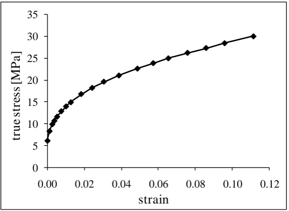
except the polyethylene liner which was modelled as non-linear elastic-plastic behaviour with
137
the plastic stress-stain constitutive relationship showing in Fig. 2 [33,34]. The femoral head
138
was modelled as a rigid body as the elastic modulus of the metallic femoral head is about 200
139
times that for polyethylene liner. The mechanical properties for the materials are presented in
140
Table 1. The FE model comprised approximately 92,000 elements, including triangular shell
141
elements for the cortical bone with element sizes less than 3 mm, tetrahedral elements for the
142
cancellous bone with element sizes less than 3 mm, hexahedral and wedge elements for the
143
prosthetic components with element sizes less than 0.8 mm and 0.3 mm respectively. Mesh
144
converge studies were conducted for the FE model under normal walking activity under cup
145
inclination angle of 75º and anteversion angle of 0º, an assumed extreme condition under
146
which the polyethylene liner was assumed to have the worst mechanical behaviour with
147
respect to the contact pressures, von Mises stresses and plastic strain. The results showed that
148
when the element size was reduced by half, the change in any of the parameters of interest
149
was within 5%.
150
A sliding contact formulation was applied both on the articulating surface between the
151
femoral head and polyethylene liner and at the interface between the acetabular shell and
6
polyethylene liner, with friction coefficients of 0.083 and 0.15 respectively [35,36]. The
153
nodes situated at the sacroiliac joint and about the pubic symphysis were fully constrained.
154
All relative movements were prevented between the pelvic bone and the acetabular shell,
155
simulating a situation where the porous sintered coating and in-grown bone were well
156
bonded. The centre of the femoral head was constrained in rotational degrees of freedom and
157
allowed to move freely along the translational free degrees of freedom to allow
self-158
alignment. The validation of the FE model was presented in a previous study, which
159
demonstrated that good agreements of contact areas at the articulating surface were obtained
160
between the FE predictions and experimental measurements using Leeds Prosim hip joint
161
simulator [34].
162
The physiological loadings of six different human activities, which were measured in vivo
163
previously using an instrumented total hip prosthesis [37], were applied to the FE model.
164
These activities were as follows: normal walking (NW), ascending stairs (AS), descending
165
stairs (DS), standing up (SU), sitting down (SD) and knee bending (KB). In order to consider
166
the specific direction and orientation of the forces, the three components of the resultant hip
167
joint forces relative to the pelvis coordinate system in the in vivo study [37] were exported
168
and discretized into 22 or 23 steps, which were then applied directly to the centre of the
169
femoral head in the FE model in a quasi-static manner, as shown in Fig 3. At this case, the
170
global coordinate system in the FE model was assumed to be aligned with the pelvis
171
coordinate system in the in vivo study [37]. A total of 20 orientations of cup angles were
172
considered, with inclination angles varying between 35º and 75º and anteversion angles
173
varying between 0º and 30º, both in 10º increments. The FE analysis was performed using
174
ABAQUS software package (Version 6.9; Dassault Syste`mes Simulia Corp., Providence, RI,
175
United States). Edge loading at the articulating surface was detected and evaluated at each
176
instance during the whole cycle of these activities. In the present study, edge loading was
177
defined to occur when the contact patch between the femoral head and polyethylene liner
178
extends over the rim of the liner, as shown in Fig. 4.
179 180
3 Results 181
7
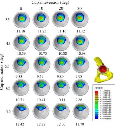
Fig. 5 shows the distribution and peak value of contact pressures on the articulating surface of
183
the polyethylene liner with different cup inclination and anteversion angles at instance of
184
17% gait of normal walking activity.
185
Generally, the areas of the contact patch were located about the superior region of the liner
186
and shifted toward the superior edge as inclination angle increased. The peak contact pressure
187
was located at the dome spherical region at low cup inclination conditions (i.e. 35° and 45°)
188
and moved to the equatorial region when the inclination angle was increased to 75°. Edge
189
loading started to occur when the cup inclination angle increased to 65°.
190
Edge loading 191
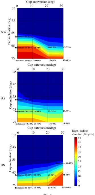
The duration of edge loading and specific instances of cycle at which edge loading occurred
192
during different activities as a function of cup angles are shown in Fig. 6.
193
Edge loading was predicted at some instances of cycle during normal walking, ascending and
194
descending stairs activities under steep cup inclination angle conditions (≥ 55°). No edge
195
loading was predicted for standing up, sitting down and knee bending cases for all cup angles
196
considered. For normal walking and ascending stair cases, the combination of steep cup
197
inclination and low anteversion was more likely to cause edge loading. For example, for
198
normal walking activity, the proportion of gait cycle when edge loading occurred increased
199
from 5% (at specific instances of 50-55% of gait cycle) to 50% (at specific instances of
10-200
60% of gait cycle) as cup inclination angles increased from 55° to 75° with anteversion of 0°.
201
With cup inclination of 65°, the proportion of gait cycle when edge loading occurred
202
decreased from 40% to 13% when the cup anteversion angles increased from 0° to 30°. In
203
contrast, for descending stair activity, the combination of steep cup inclination and high
204
anteversion tended to induce edge loading.
205
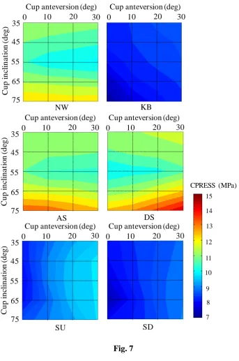
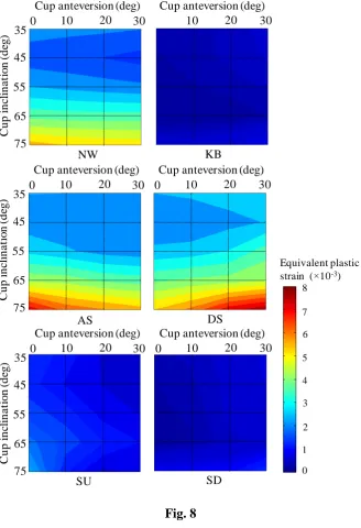
Effect of activities, cup angles and edge loading on contact mechanics 206
The activities and cup angles were found to have a synergistic effect on the peak contact
207
pressure at the articulating surface and equivalent plastic strain of the liner (Fig. 7 and 8).
208
Edge loading caused elevated peak contact pressure at the articulating surface and marked
209
increase of peak equivalent plastic strain of the polyethylene liner (Fig. 7, 8 and 9). For
210
normal walking, ascending and descending stairs activities, the cup inclination angles had
211
marked effect on the peak contact pressure and equivalent plastic strain while the cup
212
anteversion angles had minor effect. Considering the cup anteversion, the peak contact
213
pressure over the whole cycle firstly decreased by approximately 12%, 5%-9% and
8
14% for normal walking, ascending stair and descending stair activities respectively when the
215
cup inclination angle increased from 35° to 55°, and then increased by about 18%-26%,
22%-216
28% and 27%-33% respectively for the three activities when the cup inclination angle
217
increased to 75°, where edge loading occurred (Fig. 7). Correspondingly, the peak equivalent
218
plastic strain over the whole cycle firstly decreased by approximately 31%-53%, 13%-21%
219
and 15%-28% when the cup inclination increased from 35° to 45° and then increased by
220
about 234%-306%, 179%-231% and 178%-213% when the cup inclination increased to 75°
221
for the three activities respectively.
222
In contrast, for standing up, sitting down and knee bending activities, the cup anteversion
223
angles were found to have dominated effect on the peak contact pressure and equivalent
224
plastic strain. Considering the cup inclination, the peak contact pressure and equivalent
225
plastic strain over the whole cycle increased by approximately 14%-24% and 88%-164%,
226
2%-21% and 57%-148%, 4%-12% and 56%-138% for standing up, sitting down and knee
227
bending activities respectively when the cup anteversion increased from 0° to 30°.
228 229
4 Discussion 230
Edge loading as an adverse condition that could cause unexpected clinical problems has
231
attracted more and more attentions in biomechanics fields [38,39]. The factors that may lead
232
to edge loading have been recognized and were generally associated with the component
233
positions (i.e. cup angles, head offset/microlateralisation), prosthetic design (i.e. radial
234
clearance, cup coverage), impingement and activities. The contribution and effect of
235
component malposition, prosthetic design, impingement and dislocation on the edge loading
236
of hip replacement have been investigated in a number of previous studies
[9,10,23-25,40-237
42]. The primary purposes of the present study were therefore to investigate the effect of cup
238
orientations and daily activities on the contact mechanics and occurrence of edge loading for
239
a modular MoP THR. The duration of edge loading and instances of cycle at which edge
240
loading occurred during six daily activities were evaluated. To the authors’ acknowledge, this 241
was the first to quantify the duration and period of time of true edge loading in THRs during
242
different daily activities, by considering the deformation of pelvic bone and components.
243
The FE simulations showed that an individual’s activity patterns played an important role on
244
the occurrence of edge loading in MoP THR. For the THR considered in the present study,
245
edge loading occurred at some instances during normal walking, ascending and descending
9
stairs activities under steep cup inclination conditions. With increased cup inclination angles,
247
the duration and period of time over which the hip experienced edge loading increased. These
248
were supported by an in vivo study to evaluate edge loading in MoM hip resurfacing patients
249
with and without pseudotumours which showed that edge loading in patients with
well-250
functioning MoM hip resurfacing arthroplasty was observed during functional activities and
251
that edge loading in the hips with pseudotumours (which was associated with higher cup
252
inclination) occurred for a significantly longer period of time compared to that without
253
pseudotumours [17]. The present study also showed that the duration and period of time of
254
edge loading was activity-dependent, with the longest duration of edge loading being
255
observed for normal walking activity. No edge loading was predicted for standing up, sitting
256
down and knee bending activities. These observations, however, were found to be different
257
from the previous in vivo study which indicated that edge loading also occurred for rising
258
from or sitting down to chair activity [17]. A retrieval study conducted by Esposito et al also
259
demonstrated both anterior and posterior edge loading in retrieval ceramic components and
260
they assumed that posterior edge loading may occur during activities such as climbing stairs
261
or rising from a chair [43]. The different conclusions between the present study and the in
262
vivo and retrieval studies may be due to several reasons. Firstly, in vivo study, edge loading
263
was defined to occur when the locus of the force vector intersection with the acetabular
264
component was located within the areas where the distance to the edge of the component was
265
no larger than 10% of the component radius, while in the present study, edge loading was
266
defined as the case when the contact patch extends over the rim of the component. The
267
limitation of the in vivo study was that although the force vector for the rising up/sitting down
268
activities was located in the edge loading zone defined in the in vivo study for a longer period
269
of time, the force magnitude was smaller compared to that in normal walking, ascending and
270
descending stairs activities, leading to a smaller contact patch at the bearing surface of the
271
component. Therefore, if the radius of the contact patch was smaller than 10% of the
272
component radius, edge loading would not occur. However, at this case, edge loading was
273
assumed to still occur in the in vivo study. Secondly, the different design of prosthesis
274
considered in the present study (MoP) and the in vivo (MoM) and retrieval (CoC) studies may
275
be an important factor causing the different conclusions. In the present study, the radial
276
clearance between femoral head and polyethylene liner was 0.3 mm. If a smaller clearance is
277
considered, the contact stresses will be decreased and the contact areas will be increased. At
278
this case, the contact patch will potentially extend over the rim of the polyethylene liner,
279
causing posterior edge loading for rising up/sitting down activities. In fact, in the present
10
simulation, for most instances of rising up/sitting down activities, the contact patch was prone
281
to locating at the posterior area of the bearing surface, having the potential to cause posterior
282
edge loading. Therefore, the effect of prosthetic design such as radial clearances and cup
283
coverages on the occurrence of edge loading will be examined in future studies. Thirdly, the
284
posterior edge loading observed in the retrieval study may be caused by some adverse
285
conditions such as impingement of the components, which has been reported to be common
286
for MoP THR in retrieval studies [28,44]. However, the adverse condition of impingement
287
was not considered in the present study.
288
Previous studies have shown that the cup inclination of no larger than 45° is best for
289
achieving stability and preventing wear [45,46]. The present study supported this conclusion
290
that no edge loading occurred when the cup inclination angle was no larger than 45° for all
291
the activities and cup anteversion angles considered. In addition, the cup anteversion was
292
found to have a crucial effect on the duration and occurrence of edge loading as well. For
293
example, under a steep cup inclination angle of 65°, the duration of occurrence of edge
294
loading during normal walking was over 40% gait cycle under anteversion angle of 0°, which
295
reduced to less than 15% gait cycle under anteversion angle of 30°. Edge loading was most
296
likely to occur at the instances between 45-55%, 15-20% and 90-95% cycle time for normal
297
walking, ascending and descending stairs activities respectively. This was a result of the
298
synergistic effect between the force vector and magnitude. Indeed, in a paper to investigate
299
the effect of motion patterns on edge-loading of MoM hip resurfacing, Mellon et al.
300
suggested that the force vector at the instance of 60% gait cycle was closer to the edge of
301
component than any other time during the stance phase of gait [26].
302
The analysis of the effect of cup angles on the contact pressures at the articulating surface
303
showed that mild increase of the cup inclination angle resulted in decreased peak contact
304
pressure at the articulating surface of the modular MoP THR for normal walking, ascending
305
and descending stairs activities, which was found to be different from the non-modular THR
306
[33,45]. This was probably due to the factor that at lower cup inclination condition (i.e. 35º),
307
the contact area was mainly located in the dome spherical region of the polyethylene liner in
308
modular MoP THR. When the cup inclination angles increased (i.e. 45º, 55º), the contact area
309
moved to the transition area between the dome spherical region and equatorial region. The
310
different deformation of the polyethylene liner due to the different stiffness of support behind
311
the liner would cause enlarged contact areas at this transition region, leading to decreased
312
contact pressures [47,48]. When the cup inclination angle increased further (i.e. 75º), edge
11
loading would occur and the contact pressures increased. For all cup angles conditions and
314
activities considered, plastic deformation of the polyethylene liner was predicted. Similarly,
315
the equivalent plastic strain of the polyethylene liner was first increased and then decreased
316
with increased cup inclination angles.
317
It is well known that the cup inclination angles had a marked effect on the contact mechanics
318
and stability of hip joint replacement under both normal and adverse conditions
319
[13,33,45,47]. The present study demonstrated that for normal walking, ascending and
320
descending stairs activities, the cup inclination angles had a leading effect on the contact
321
pressures at the articulating surface and equivalent plastic strain of the polyethylene liner,
322
while for standing up, sitting down and knee bending activities, the cup anteversion had
323
dominated impact. Therefore, it is suggested that the importance of cup anteversion should be
324
considered and recognized during the positioning of cup component in clinical practice.
325
The FE analysis also showed that edge loading caused elevated contact pressures at the
326
articulating surface and equivalent plastic strain in the components, which was consistent
327
with previous studies [13,14]. In particular, there was a substantial increase in the equivalent
328
plastic strain when the cup inclination increased from 55º to 65º and from 65º to 75º for
329
normal walking, ascending and descending stairs activities, where edge loading occurred.
330
This indicated that obvious plastic deformation would occur under these conditions, as
331
observed in previous in vitro study [21]. The amplified plastic deformation could potentially
332
induce creep and fatigue of the liner [49,50], and also pitting and delamination of the surface
333
at this area, leading to fatigue damage and fracture of the component [51]. Therefore, it is
334
indicated that the positioning of the component is important clinically to avoid severe plastic
335
deformation of the component and that lower cup inclination angle remains a
336
recommendation for implant positioning of the modular THRs.
337
There are several limitations to the present study. First, the muscle and ligament surrounding
338
the hip were not considered in the present study, which was proved to play an important role
339
in the stability of hip replacements [52]. Previous study has shown that the muscles inserted
340
into the distal femur, patella or tibia can contribute to edge loading of well-positional cup
341
[31]. Therefore, a large-scale computational model that integrate the FE model and
342
musculoskeletal dynamic model could be developed for getting a better understanding of
343
edge loading during different daily activities in future studies. Second, only six activities
344
were considered in the present study whereas a broad variety of challenge maneuver ensue in
345
activities of daily living which would cause adverse complications such as impingement and
12
dislocation [53]. However, the activities considered in the present study did represent the
347
most frequent activities for human daily living [37]. Third, homogeneous, isotropic and linear
348
material properties for the bone and uniform thickness of cortical bone were assumed in the
349
present study. However, a real bone should have a non-homogenous, anisotropic property
350
[54], and previous studies have shown that the thickness of the cortical bone layer and the
351
material properties of the bone were site-dependent and bone density-dependent [55,56]. The
352
effect of bone properties on the results should be evaluated and addressed in the future
353
studies. Moreover, lubrication may play an important role in the occurrence of edge loading
354
which was not considered in the present study. However, a recent study to investigate the
355
contact mechanics and lubrication of ceramic-on-metal total hip replacements demonstrated
356
that the profiles and magnitude of the film pressures calculated using elastohydrodynamic
357
lubrication (EHL) theory was closely similar to those of the dry contact pressures calculated
358
using FE modelling [57]. Finally, the femoral head was assumed to be located perfectly
359
within the liner during all activities in the FE simulation. However, in deep flexion activities
360
such as standing up or sitting down activities, there is possibilities that impingement of the
361
components occurs, causing a posterior subluxation of the femoral head and posterior edge
362
loading in the acetabular liner. These were not simulated in the present study.
363
Despite these limitation listed above, the present study suggested that edge loading would
364
occur during some of the functional daily activities such as normal walking,
365
ascending/descending stairs under steep cup inclination conditions. Edge loading induced by
366
these daily activities and steep cup inclination can result in elevated contact pressures at the
367
articulating surface and equivalent plastic strain in the component for the modular MoP THR.
368
Therefore, it is suggested that clinically it is important to optimise the orientation of the
369
components in hip joint replacements to avoid edge loading that may occur during activities
370
of daily living.
371 372
Acknowledgements 373
This work was funded through WELMEC, a Centre of Excellence in Medical Engineering
374
funded by the Wellcome Trust and EPSRC, under grant number 088908/Z/09/Z. Research
375
was also supported by the EPSRC Centre for Innovative Manufacturing in Medical Devices.
376
JF is an NIHR senior investigator and work is supported in part through the NIHR Leeds
377
Musculoskeletal Biomedical Research Unit.
13 Conflict of interest
379
John Fisher is a consultant to DePuy Synthes Joint Reconstruction.
380
381
Ethical approval 382
Not required.
383
384
References 385
[1] De Haan R, Campbell PA, Su EP, De Smet KA. Revision of metal-on-metal resurfacing 386
arthroplasty of the hip: the influence of malpositioning of the components. J Bone Joint Surg Br 387
2008; 90(9):1158-63. 388
[2] Pandit H, Glyn-Jones S, McLardy-Smith P, Gundle R, Whitwell D, Gibbons CL, Ostlere S, 389
Athanasou N, Gill HS, Murray DW. Pseudotumours associated with metal-on-metal hip 390
resurfacings. J Bone Joint Surg Br 2008; 90(7): 847-51. 391
[3] Walter WL, Kurtz SM, Esposito C, Hozack W, Holley KG, Garino JP, Tuke MA. Retrieval 392
analysis of squeaking alumina ceramic-on-ceramic bearings. J Bone Joint Surg Br 2011; 93(12): 393
1597-601. 394
[4] Stafford GH, Islam SU, Witt JD. Early to mid-term results of ceramic-on-ceramic total hip 395
replacement: analysis of bearing-surface-related complications. J Bone Joint Surg Br 2011; 396
93(8): 1017-20. 397
[5] Stanat SJ, Capozzi JD. Squeaking in third- and fourth-generation ceramic-on-ceramic total hip 398
arthroplasty: meta-analysis and systematic review. J Arthroplasty 2012; 27(3): 445-53. 399
[6] Kwon YM, Glyn-Jones S, Simpson DJ, Kamali A, McLardy-Smith P, Gill HS, Murray DW. 400
Analysis of wear of retrieved metal-on-metal hip resurfacing implants revised due to 401
pseudotumours. J Bone Joint Surg Br 2010; 92(3): 356-61. 402
[7] Matthies A, Underwood R, Cann P, Ilo K, Nawaz Z, Skinner J, Hart AJ. Retrieval analysis of 240 403
metal-on-metal hip components, comparing modular total hip replacement with hip resurfacing. J 404
14
[8] Morlock MM, Bishop N, Zustin J, Hahn M, Rüther W, Amling M. Modes of implant failure after 406
hip resurfacing: morphological and wear analysis of 267 retrieval specimens. J Bone Joint Surg 407
Am 2008; 90 (Suppl 3): 89-95. 408
[9] Mak MM, Besong AA, Jin ZM, Fisher J. Effect of microseparation on contact mechanics in 409
ceramic-on-ceramic hip joint replacements. Proc Inst Mech Eng H 2002; 216(6): 403-8. 410
[10] Underwood RJ, Zografos A, Sayles RS, Hart A, Cann P. Edge loading in metal-on-metal hips: 411
low clearance is a new risk factor. Proc Inst Mech Eng H 2012; 226(3): 217-26. 412
[11] Al-Hajjar M, Leslie IJ, Tipper J, Williams S, Fisher J, Jennings LM. Effect of cup inclination 413
angle during microseparation and rim loading on the wear of BIOLOX® delta ceramic-on-414
ceramic total hip replacement. J Biomed Mater Res B Appl Biomater 2010; 95(2):263-8. 415
[12] Sariali E, Stewart T, Jin Z, Fisher J. In vitro investigation of friction under edge-loading 416
conditions for ceramic-on-ceramic total hip prosthesis. J Orthop Res 2010; 28(8): 979-85. 417
[13] Hua X, Li J, Wang L, Jin Z, Wilcox R, Fisher J. Contact mechanics of modular metal-on-418
polyethylene total hip replacement under adverse edge loading conditions. J Biomech 2014; 419
47(13): 3303-9. 420
[14] Liu F, Williams S, Fisher J. Effect of microseparation on contact mechanics in metal-on-metal 421
hip replacements-A finite element analysis. J Biomed Mater Res B Appl Biomater 2015; 103(6): 422
1312-9. 423
[15] Williams S, Jalali-Vahid D, Brockett C, Jin Z, Stone MH, Ingham E, Fisher J. Effect of swing 424
phase load on metal-on-metal hip lubrication, friction and wear. J Biomech 2006; 39(12): 2274-425
81. 426
[16] Leslie IJ, Williams S, Isaac G, Ingham E, Fisher J. High cup angle and microseparation increase 427
the wear of hip surface replacements. Clin Orthop Relat Res 2009; 467(9): 2259-65. 428
[17] Kwon YM, Mellon SJ, Monk P, Murray DW, Gill HS. In vivo evaluation of edge-loading in 429
metal-on-metal hip resurfacing patients with pseudotumours. Bone Joint Res 2012; 1(4): 42-9. 430
[18] Stewart T, Tipper J, Streicher R, Ingham E, Fisher J. Long-term wear of HIPed alumina on 431
alumina bearings for THR under microseparation conditions. J Mater Sci Mater Med 2001; 432
12(10-12): 1053-6. 433
[19] Jarrett CA, Ranawat AS, Bruzzone M, Blum YC, Rodriguez JA, Ranawat CS. The squeaking 434
hip: a phenomenon of ceramic-on-ceramic total hip arthroplasty. J Bone Joint Surg Am 2009; 435
15
[20] Al-Hajjar M, Jennings LM, Begand S, Oberbach T, Delfosse D, Fisher J. Wear of novel ceramic-437
on-ceramic bearings under adverse and clinically relevant hip simulator conditions. J Biomed 438
Mater Res B Appl Biomater 2013; 101(8): 1456-62. 439
[21] Williams S, Butterfield M, Stewart T, Ingham E, Stone M, Fisher J. Wear and deformation of 440
ceramic-on-polyethylene total hip replacements with joint laxity and swing phase 441
microseparation. Proc Inst Mech Eng H 2003; 217(2): 147-53. 442
[22] Halma JJ, Señaris J, Delfosse D, Lerf R, Oberbach T, van Gaalen SM, de Gast A. Edge loading 443
does not increase wear rates of ceramic-on-ceramic and metal-on-polyethylene articulations. J 444
Biomed Mater Res B Appl Biomater 2014; 102(8): 1627-38. 445
[23] Wang L, Williams S, Udofia I, Isaac G, Fisher J, Jin Z. The effect of cup orientation and 446
coverage on contact mechanics and range of motion of metal-on-metal hip resurfacing 447
arthroplasty. Proc Inst Mech Eng H 2012; 226(11): 877-86. 448
[24] Brown TD, Elkins JM, Pedersen DR, Callaghan JJ. Impingement and dislocation in total hip 449
arthroplasty: mechanisms and consequences. Iowa Orthop J 2014; 34: 1-15. 450
[25] Malik A1, Maheshwari A, Dorr LD. Impingement with total hip replacement. J Bone Joint Surg 451
Am 2007; 89(8): 1832-42. 452
[26] Mellon SJ, Kwon YM, Glyn-Jones S, Murray DW, Gill HS. The effect of motion patterns on 453
edge-loading of metal-on-metal hip resurfacing. Med Eng Phys 2011; 33(10): 1212-20. 454
[27] Lewinnek GE, Lewis JL, Tarr R, Compere CL, Zimmerman JR. Dislocations after total hip-455
replacement arthroplasties. J Bone Joint Surg Am 1978; 60(2): 217-20. 456
[28] Wroblewski BM. Direction and rate of socket wear in Charnley low-friction arthroplasty. J Bone 457
Joint Surg Br 1985; 67(5):757-61. 458
[29] Kennedy JG, Rogers WB, Soffe KE, Sullivan RJ, Griffen DG, Sheehan LJ. Effect of acetabular 459
component orientation on recurrent dislocation, pelvic osteolysis, polyethylene wear, and 460
component migration. J Arthroplasty 1998; 13(5):530-4. 461
[30] Schmalzried TP, Guttmann D, Grecula M, Amstutz HC. The relationship between the design, 462
position, and articular wear of acetabular components inserted without cement and the 463
development of pelvic osteolysis. J Bone Joint Surg Am. 1994;76(5):677-88. 464
[31] van Arkel RJ, Modenese L, Phillips AT, Jeffers JR. Hip abduction can prevent posterior edge 465
loading of hip replacements. J Orthop Res 2013; 31(8):1172-9. 466
[32] Udofia I, Liu F, Jin Z, Roberts P, Grigoris P. The initial stability and contact mechanics of a 467
16
[33] Hua X, Wroblewski BM, Jin Z, Wang L. The effect of cup inclination and wear on the contact 469
mechanics and cement fixation for ultra high molecular weight polyethylene total hip 470
replacements. Med Eng Phys 2012; 34(3): 318-25. 471
[34] Hua X, Wang L, Al-Hajjar M, Jin Z, Wilcox RK, Fisher J. Experimental validation of finite 472
element modelling of a modular metal-on-polyethylene total hip replacement. Proc Inst Mech 473
Eng H 2014; 228(7): 682-92. 474
[35] Romero F, Amirouche F, Aram L, Gonzalez MH. Experimental and analytical validation of a 475
modular acetabular prosthesis in total hip arthroplasty. J Orthop Surg Res 2007; 2:7. 476
[36] Amirouche F, Romero F, Gonzalez M, Aram L. Study of micromotion in modular acetabular 477
components during gait and subluxation: a finite element investigation. J Biomech Eng 2008; 478
130(2): 021002. 479
[37] Bergmann G, Deuretzbacher G, Heller M, Graichen F, Rohlmann A, Strauss J, Duda GN. Hip 480
contact forces and gait patterns from routine activities. J Biomech 2001; 34(7): 859-71. 481
[38] Fisher J. Bioengineering reasons for the failure of metal-on-metal hip prostheses: an engineer's 482
perspective. J Bone Joint Surg Br 2011; 93(8): 1001-4. 483
[39] Harris WH. Edge loading has a paradoxical effect on wear in metal-on-polyethylene total hip 484
arthroplasties. Clin Orthop Relat Res 2012; 470(11): 3077-82. 485
[40] Langton DJ, Jameson SS, Joyce TJ, Webb J, Nargol AV. The effect of component size and 486
orientation on the concentrations of metal ions after resurfacing arthroplasty of the hip. J Bone 487
Joint Surg Br 2008; 90(9): 1143-51. 488
[41] De Haan R, Campbell PA, Su EP, De Smet KA. Revision of metal-on-metal resurfacing 489
arthroplasty of the hip: the influence of malpositioning of the components. J Bone Joint Surg Br 490
2008; 90(9): 1158-63. 491
[42] Elkins JM, O'Brien MK, Stroud NJ, Pedersen DR, Callaghan JJ, Brown TD. Hard-on-hard total 492
hip impingement causes extreme contact stress concentrations. Clin Orthop Relat Res 2011; 493
469(2): 454-63. 494
[43] Esposito CI, Walter WL, Roques A, Tuke MA, Zicat BA, Walsh WR, Walter WK. Wear in 495
alumina-on-alumina ceramic total hip replacements: a retrieval analysis of edge loading. J Bone 496
Joint Surg Br 2012; 94(7): 901-7. 497
[44] Shon WY, Baldini T, Peterson MG, Wright TM, Salvati EA. Impingement in total hip 498
arthroplasty a study of retrieved acetabular components. J Arthroplasty 2005; 20(4): 427-35. 499
[45] Patil S, Bergula A, Chen PC, Colwell CW Jr, D'Lima DD. Polyethylene wear and acetabular 500
17
[46] Robinson RP, Simonian PT, Gradisar IM, Ching RP. Joint motion and surface contact area 502
related to component position in total hip arthroplasty. J Bone Joint Surg Br 1997; 79(1): 140-6. 503
[47] Kurtz SM, Edidin AA, Bartel DL. The role of backside polishing, cup angle, and polyethylene 504
thickness on the contact stresses in metal-backed acetabular components. J Biomech 1997; 30(6): 505
639-42. 506
[48] Kurtz SM, Ochoa JA, White CV, Srivastav S, Cournoyer J. Backside nonconformity and locking 507
restraints affect liner/shell load transfer mechanisms and relative motion in modular acetabular 508
components for total hip replacement. J Biomech 1998; 31(5): 431-7. 509
[49] Penmetsa JR, Laz PJ, Petrella AJ, Rullkoetter PJ. Influence of polyethylene creep behavior on 510
wear in total hip arthroplasty. J Orthop Res 2006;24(3):422-7. 511
[50] Hertzberg, R.W., Manson, J.A. Fatigue of engineering plastics. New York: Academice press 512
1980. 513
[51] Edidin AA, Pruitt L, Jewett CW, Crane DJ, Roberts D, Kurtz SM. Plasticity-induced damage 514
layer is a precursor to wear in radiation-cross-linked UHMWPE acetabular components for total 515
hip replacement. Ultra-high-molecular-weight polyethylene. J Arthroplasty 1999; 14(5): 616-27. 516
[52] Elkins JM, Kruger KM, Pedersen DR, Callaghan JJ, Brown TD. Edge-loading severity as a 517
function of cup lip radius in metal-on-metal total hips--a finite element analysis. J Orthop Res 518
2012; 30(2): 169-77. 519
[53] Nadzadi ME, Pedersen DR, Yack HJ, Callaghan JJ, Brown TD. Kinematics, kinetics, and finite 520
element analysis of commonplace maneuvers at risk for total hip dislocation. J Biomech 2003; 521
36(4): 577-91. 522
[54] Dalstra M, Huiskes R, van Erning L. Development and validation of a three-dimensional finite 523
element model of the pelvic bone. J Biomech Eng 1995; 117(3): 272-8. 524
[55] Anderson AE, Peters CL, Tuttle BD, Weiss JA. Subject-specific finite element model of the 525
pelvis: development, validation and sensitivity studies. J Biomech Eng 2005; 127(3): 364-73. 526
[56] Leung AS, Gordon LM, Skrinskas T, Szwedowski T, Whyne CM. Effects of bone density 527
alterations on strain patterns in the pelvis: application of a finite element model. Proc Inst Mech 528
Eng H 2009; 223(8): 965-79. 529
[57] Meng Q, Liu F, Fisher J, Jin ZM. Contact mechanics and lubrication analyses of ceramic-on-530
metal total hip replacements. Tribology International 2013; 63: 51-60. 531
18 List of figure captions:
534
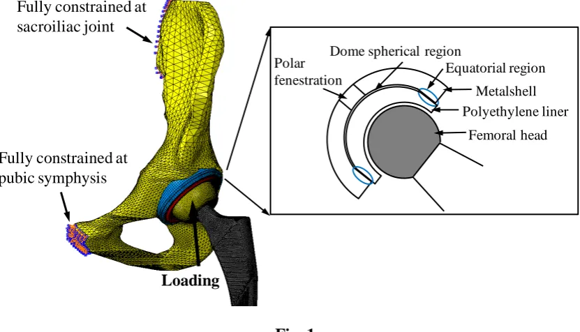
Fig. 1 The FE modelling and boundary conditions, and cross-section of the modular MoP 535
THR showing the detailed structure and features.
536
Fig. 2 The plastic stress-strain relation for the polyethylene liner [33,34]. 537
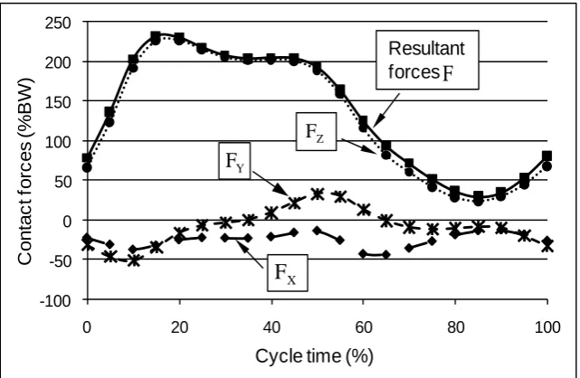
Fig. 3 Resultant hip joint forces during normal walking. The resultant force was converted to 538
three components ( , , ) and computed as . During the simulation
539
process, the resultant hip joint force was discretized into 23 steps.
540
Fig. 4 The definition of edge loading in MoP THR in the present study. Left: edge loading 541
did not occur as the contact patch was within the inner surface of the liner; right: edge
542
loading occurred as the contact patch extended over the rim of the liner.
543
Fig. 5 The distribution and peak value of the contact pressures (MPa) on the articulating 544
surface of the polyethylene liner as a function of cup inclination and anteversion angles at
545
17% gait cycle during normal walking activity.
546
Fig. 6 The duration of edge loading and specific instances at which edge loading occurred on 547
the articulating surface of the liner as a function of cup inclination and anteversion angles
548
during different activities (NW: normal walking, AS: ascending stairs, DS: descending
549
stairs). No edge loading was predicted for standing up, sitting down and knee bending
550
activities.
551
Fig. 7 The peak contact pressure (MPa) at the articulating surface over the whole cycle as a 552
function of cup inclination and anteversion angles during different activities ((NW: normal
553
walking, AS: ascending stairs, DS: descending stairs, SU: standing up, SD: sitting down, KB:
554
knee bending).
555
Fig. 8 The peak equivalent plastic strain in the polyethylene liner over the whole cycle as a 556
function of cup inclination and anteversion angles during different activities ((NW: normal
557
walking, AS: ascending stairs, DS: descending stairs, SU: standing up, SD: sitting down, KB:
558
knee bending).
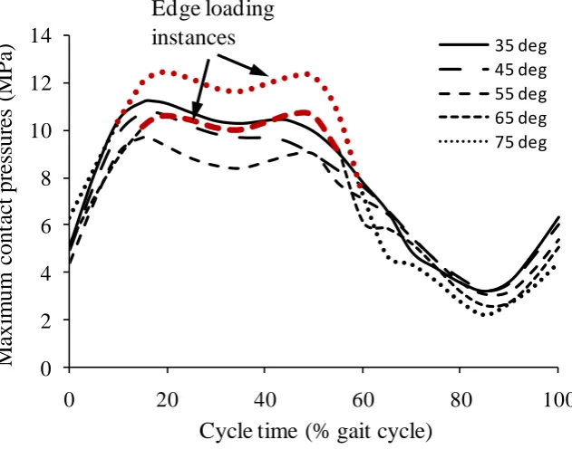
559
Fig. 9 The maximum contact pressure at the articulating surface of liner during normal 560
walking for different cup inclination angles with cup anteversion angle of 10°. The bold red
561
lines represent the instances when edge loading occurred.
19 563
Fig. 1 564
565 566 567 568 569 570 571 572 573 574 575
Fully constrained at sacroiliac joint
Fully constrained at pubic symphysis
Loading
Metalshell Polyethylene liner Polar
fenestration
20 576
Fig. 2 577
578 579 580 581 582 583 584 585 586 587 588 589
0 5 10 15 20 25 30 35
0.00 0.02 0.04 0.06 0.08 0.10 0.12
tr
u
e
st
re
ss
[
M
P
a
]
21 590
Fig. 3 591
592 593 594 595 596 597 598 599 600 601 602 603 604
-100 -50 0 50 100 150 200 250
0 20 40 60 80 100
C
o
n
ta
c
t
fo
rc
e
s
(%
BW
)
Cycle time (%)
Resultant
forces F
X
F
Y F
Z
22 605
Fig. 4 606
607 608 609 610 611
23 612
Fig. 5 613
12.42 12.28 12.00 11.70
10.71 10.41 10.11 9.86
9.33 9.59 9.80 9.98
10.59 10.75 10.88 10.98
11.18 11.23 11.16 11.12
S
P A
I
Cup anteversion (deg)
0
10
20
30
Cu
p
in
cl
in
at
io
n
(
d
eg
)
35
45
55
65
24 614
Fig. 6 615
NW
Cup anteversion (deg)
0 10 20 30
C u p in cl in a ti o n ( d eg ) 35 45 55 65 75 Instances: 50-55% Instances: 15-55% Instances: 10-60%
15-55% 40-55% 42-55%
10-60% 15-60% 15-60% Cup anteversion (deg)
0 10 20 30
C u p in cl in a ti o n ( d eg ) 35 45 55 65 75 Instances: 10-20% Instances: 10-35% Instances: 10-50%
10-35% 15-35% 15-35%
10-50% 15-50% 15-50%
AS
DS
Cup anteversion (deg)
0 10 20 30
C u p in cl in a ti o n ( d eg ) 35 45 55 65 75 Instances: 90-95% Instances: 85-95% Instances: 55-95%
80-95% 75-95% 55-95%
55-95% 55-95% 55-100% 0
25 616
Fig. 7 617
618
NW KB
Cup anteversion (deg)
0 10 20 30
C
u
p
in
cl
in
a
ti
o
n
(
d
eg
) 35
45
55
65
75
Cup anteversion (deg)
0 10 20 30
Cup anteversion (deg)
0 10 20 30
C
u
p
in
cl
in
a
ti
o
n
(
d
eg
) 35
45
55
65
75
Cup anteversion (deg)
0 10 20 30
Cup anteversion (deg)
0 10 20 30
C
u
p
in
cl
in
a
ti
o
n
(
d
eg
) 35
45
55
65
75
Cup anteversion (deg)
0 10 20 30
7 8 9 10 11 12 13 14 15
CPRESS (MPa)
AS DS
26 619 Fig. 8 620 621 622
Cup anteversion (deg)
0 10 20 30
C u p in cl in a ti o n ( d eg ) 35 45 55 65 75
Cup anteversion (deg)
10 20 30
NW KB
Cup anteversion (deg)
0 10 20 30
C u p in cl in a ti o n ( d eg ) 35 45 55 65 75
Cup anteversion (deg)
0 10 20 30
AS DS
Cup anteversion (deg)
0 10 20 30
C u p in cl in a ti o n ( d eg ) 35 45 55 65 75
Cup anteversion (deg)
0 10 20 30
SU SD 0
27 623
Fig. 9 624
625 626 627 628 629 630 631 632 633 634 635 636 637 638 639
0 2 4
6
8 10
12
14
0 20 40 60 80 100
M
axi
m
um
c
ont
ac
t
pr
es
sur
es
(
M
P
a)
Cycle time (% gait cycle)
35 deg 45 deg 55 deg 65 deg 75 deg Edge loading
28
Table 1 Material properties for the components used in the present study [32,33,34]. 640
Components Materials Young’s modulus (GPa) Poisson’s ratio
Polyethylene liner UHMWPE 1 0.4
Metal shell Titanium 116 0.25
Cortical shell Cortical bone 17 0.3
Cancellous bone Cancellous bone 0.8 0.2
![Table 1 Material properties for the components used in the present study [32,33,34].](https://thumb-us.123doks.com/thumbv2/123dok_us/7849191.177948/29.595.78.519.102.220/table-material-properties-components-used-present-study.webp)
