UNIVERSITI TEKNIKAL MALAYSIA MELAKA
TOPOLOGY OPTIMIZATION OF MOLD BASE STRUCTURE
This report submitted in accordance with requirement of the Universiti Teknikal Malaysia Melaka (UTeM) for the Bachelor Degree of Engineering Technology
(Product Design) (Hons.)
BIZORA BINTI RAMLI B071310924 920422-08-6652
i
DECLARATION
I hereby, declared this report entitled “Topology Optimization of Mold Base Structure” is the results of my own research except as cited in references.
Signature : ……….
Author’s Name : Bizora Binti Ramli
ii
APPROVAL
This report is submitted to the Faculty of Engineering Technology of UTeM as a partial fulfillment of the requirements for the degree of Bachelor of Engineering Technology (Product Design) with Honours. The member of the supervisory is as follow:
iii
ABSTRAK
Pada masa kini, bahan-bahan plastik digunakan secara meluas dalam bidang
iv
ABSTRACT
v
DEDICATION
vi
ACKNOWLEDGEMENT
Bismillahirrahmanirrahim,
Peace upon you, in the name of ALLAH, The Most Compassionate, The Most Merciful. Salawat and Salaam to our beloved Prophet, Nabi Muhammad S.A.W. With the completion of this thesis report, praise to Allah, by Him who given the chances and wisdoms.
I would like to thank to my supervisor and co supervisor, Mr. Mohd Kamal Bin Musa Engr. Mohd Faizal Bin Halim for the guidance, encouragement and finance support throughout completing this project. Sincere appreciation for sharing and teaching me the knowledge and experience skills, I would like to thank to all technicians that involved throughout the project. For believing in me and give full support of my education, I would like to give my highest gratitude my mother, Mrs Sabira Binti MatSa and my Father, Mr Ramli Bin Ramli. Without them, I wouldn’t even be here today.
vii
TABLE OF CONTENTS
DECLARATION………..i
APPROVAL...ii
ABSTRAK………...iii
ABSTRACT……….iv
DEDICATION……….v
ACKNOWLEDGEMENT………...vi
TABLE OF CONTENTS………vii
LIST OF FIGURES……….xi
LIST OF TABLE……….xii
CHAPTER 1……….1
INTRODUCTION………1
1.0 Background of study ... 1
1.1 Problem statement ... 2
1.2 Objectives ... 2
1.3 Scope ... 3
CHAPTER 2……….4
viii
2.0 Introduction of literature view ... 4
2.1 Injection molding technology ... 4
2.2 Injection molding machine ... 5
2.2.1 Injection molding cycle and process ... 8
2.2.2 Setup time in injection molding ... 9
2.3 Mold base in injection molding ... 13
2.3.1 Two plate mold ... 14
2.3.2 Three plate mold ... 15
2.3.3 Basic mould construction ... 16
2.3.4 Interchangeable Insert mould ... 19
2.3.5 Deflection in mold base ... 19
2.4 Material of Mold ... 20
2.4.1 Material Properties of mold ... 21
2.4.2 S45C Carbon Steel ... 23
2.4.3 Material for part in injection molding ... 25
2.5 Topology Optimization ... 26
2.5.1 Solid Thinking Inspire 2016 ... 28
2.5.1.1 Generating the Design Space………28
2.5.1.2 Defining Constraints………...………..29
2.5.1.3 Run the optimization………..30
CHAPTER 3………33
METHODOLOGY……….33
3.0 Overview ... 33
ix
3.2 Solid Thinking Inspire 2016 ... 36
3.3 Flow chart for optimization process ... 37
3.3.1 Create 3D model ... 38
3.3.2 Importing model into CAE Software (Solid Thinking Inspire 2016) ... 39
3.3.3 Geometric Clean Up (Optional) ... 41
3.3.4 Assign Material ... 43
3.3.5 Apply Boundary Condition (BC) ... 44
3.3.6 Run the optimization for core and cavity ... 47
3.3.7 Generate the result ... 49
3.3.8 Result of Analysis ... 49
CHAPTER 4………50
RESULT AND DISCUSSION………...50
4.0 Overview ... 50
4.1 Size of core and cavity ... 50
4.2 Core Plate ... 51
4.2.1 Original design ... 51
4.2.2 Optimizing design ... 55
4.3 Cavity Plate ... 59
4.3.1 Original cavity plate ... 59
4.3.2 Optimizing cavity ... 62
4.4 Iteration of analysis ... 66
x
CHAPTER 5………74
CONCLUSION AND RECOMMENTATION………74
5.1 Introduction ... 74
5.2 Conclusion ... 74
5.3 Recommendation ... 76
REFERENCESS………..xiii
xi
LIST OF FIGURES
Figure 2.2 (a) Reciprocating screw machine 6 Figure 2.2 (b) Preplasticizing machine 7 Figure 2.2 (c) (a) Toggle clamp and (b) Hydraulic clamp 8 Figure 2.2.2 (a) Total Setup Time for Changing the Mold Base (Refer
S.Kara)
10
[image:12.612.114.508.161.691.2]xii Figure 3.3.6 (a) Pop-up browser 48 Figure 3.3.6 (b) Run optimization 49 Figure 4.2.1 (a) Mass of original core plate 54 Figure 4.2.1 (b) Result displacement for original design of core 55 Figure 4.2.1 (c) Result stress for original design of core 55 Figure 4.2.2 (a) Suggestion design by Solid Thinking Inspire 56 Figure 4.2.2 (b) Total weight for optimizing design of core 58 Figure 4.2.2 (c) Maximum and minimum displacement for optimize
design core
59
Figure 4.2.2 (d) Area of tension and compression stress for optimize design core
59
Figure 4.3.2 The Original Design for Cavity plate 60 Figure 4.3.1 (b) Total weight of original design for cavity plate 62 Figure 4.3.1 (c) Result displacement for original design of core 62 Figure 4.3.1 (d) Result of tension and compression stress of original
design for core
63
Figure 4.3.2 (a) Suggestion design of cavity by Solid Thinking Inspire 2016
64
Figure 4.3.2 (b) Displacement new design of cavity 65 Figure 4.3.2 (c) Tension and compression stress for new design of
cavity
65
xiii
LIST OF TABLES
Table 2.2.2 (a) Example of Data Setup Time Beginning of May 2006; I-Insert, M- Mold Base, C-Color, (Reproduced from S.Kara)
11
Table 2.2.2 (b) Task of Mold Base Changing (Reproduced from S.Kara)
12
Table 2.4.2 (a) Chemical composition of S45C carbon steel 24 Table 2.4.2 (b) Material properties of S45C carbon steel 25 Table 3.3.5 (a) Short projected area 46 Table 4.5 (a) Comparison result between original design and
Optimization design of Core
69
Table 4.5 (b) Comparison generated result between original design and Optimization design of Cavity
1
CHAPTER 1
INTRODUCTION
1.0 Background of study
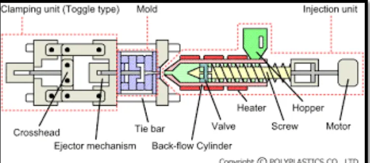
Plastic material is widely used in producing the plastic product from the bigger size into smaller part. The plastic now days, make life become easier and much comfortable. Injection molding machine had been use to manufactured the plastic product including a complex shapes or geometry shapes. The injection molding machine has divided into 2 sections that include injection unit and clamping unit. This clamping unit consists of mold base that use to produce the plastic product. It is include some element such as core plate, cavity plate, support plate, space plate and etc.
The support plate is play the important element in the mold base to ensuring the product was producing with the good shape without any defect. It is usually make up from the steel, carbon steel or aluminium with a solid structure that contribute to the heavy weight of mold base. Thus, the excessive weight of the mold base required redundant operator and increase set-up time.
2 productivity. Hence, the design modification and select the best result of support plate and spacer block will be carry out in order to achieve the less weight mold base.
1.1 Problem statement
The core and cavity plate are made from solid material such as aluminium, steel, carbon steel and copper alloy. This shape of the plate will be machine according to the size that required making a plastic product. Mostly of the core and cavity plate is heavy weight because of the solid structure. Besides that, mostly industry manufacturing purchased the mold based on the catalogue. That means, to producing the small plastic product it is not necessary to use the too heavy mold. The plastic industries and manufacturer always change the mold according to the customer demand. Thus, it will require a lot of time and more than one worker with help of machine to handle it. This situation will increase the set-up time and decrease the productivity due to the time that taken to for machine to stop operate is longer.
1.2 Objectives
To solve the problem statement above there are 3 main objective of this project which are:
To identify the mold base components.
To optimize the excessive weight of mold base structure using Solid Thinking Inspire 2016 software.
3
1.3 Scope
4
CHAPTER 2
LITERATURE VIEW
2.0 Introduction of literature view
In this chapter, it will explain clearly about the mold base structure and clamping force that occur in the clamping unit which the function is to open and close the mold part. In process to produce this literature review, all information and theory regarding the injection molding machine, mold base structure, clamping unit, setup time for assemble and disassemble mold, injection molding material, CAD and CAE are gathering from many sources such as internet and book.
2.1 Injection molding technology
Injection molding is a method commonly used in the manufacture of plastics parts. It used to create variety of products such as bottle caps, automotive dashboards, some musical instruments and some plastic products which exist today. Most of the polymer (resin) used in the production of plastic products including thermoplastics, thermosets and an elastomer. Thermoplastics more often used as a raw material because it is chosen based on the strength and function required for the final part. However, a
5 machine. Then, the melting materials are injected into the mold until it fulfills the cavity part. The products were removed from the mold by ejector after molding the materials. The process is repeated until achieved the desired production.
The benefits of injection molding to produce the plastic parts are high producing rates, high tolerance, extensive variety of material can be utilized, low labor costs and minimal of scrap losses .
2.2 Injection molding machine
An Injection molding machine knows as injection press consists of four difference elements. All elements are function to produce the plastic products by the injection molding process. The clamping mechanisms open and close the mold base along the ejecting the parts. During the injection, the injection pressure happens on the internal may cause the surface cavity space tends to open the mold at the parting line. The clamping force was supply in the clamping mechanisms to keep the mold closed (Herbert Rees, 2012) Plasticizing unit is an exclusively an extruder that heat up the plastic material in the form of pellets with the required temperature to form a fluid for injection process. The injection unit is responsible to melt (under pressure) and injecting the materials into the mold. Injection pressure is knows as a pressure applied on the injection screw where it enters the machine nozzle. Thin-walled of product need higher injection pressures to ensuring that the cavities can fill before plastic freezes. Heavy-walled products required low pressure (50 to 100 MPa). There are two injection method for plastic injection molding which are :
6 a) Reciprocating screw machine
The Reciprocating screw also standing as a RS machine or single-stage injection units in injection machine. RS machine shown in figure 2.2 (a) is the plastic injection machine the combined the extruder and the injection unit into one unit. When the melt is prepared for the next injection the extruder screw is stopped then the screw is pushed forward to inject the melt in front of the screw tip. Some of the effect of changing shot size can be avoided by using RS machine which is it prepare a shot size greater than desired for the shot.
[image:20.612.150.500.284.548.2]7 b) Preplasticizing machine
The function of preplasticizing machine (P machine) systems is to separates the extruder and the injection unit. The materials is plasticizes by an extruder than it fills it at the injection cylinder of the injection unit. These machines shown in Figure 2.2 (b) also called as two-stage injection unit. Using this P machine, the produces melt is better mixed than the RS machine and can be held at lower temperature. The shot size in the injection pot will more accurate than the RS machine. (Herbert Rees, 2012)
Figure 2.2 (b) : Preplasticizing machine
[image:21.612.146.510.267.428.2]8 kN (150 to 1000 tons). Hydromechanical clamp are usually designing for injection mold machine that have weight more than 8900 kN (1000 tons) (Anon,2004)
Figure 2.2 (c) : (a) Toggle clamp and (b) Hydraulic clamp
2.2.1 Injection molding cycle and process
[image:22.612.137.515.138.366.2]9
The plastic or resin for injection molding is usually in shape of pellet or granule and is softened or melted by heated and shearing force in a matter of seconds before being injected into the mold. Plastic pellets are filled the feed hopper which is the huge open bottomed holder to bolsters the granules down to the screw. The screw is rotate by a motor and then feeding pellets up the screw's grooves. The profundity of the screw flights diminishes towards the end of the screw closest the mold, packing the heated plastic. Due to the screw rotate, the pellets are pushed ahead in the screw and they undergo high pressure and friction. This process is important to generate heat for melting the pellets to producing the good surface or properties of parts. The channels through which the plastic streams toward the chamber will also solidify and forming an attached frame. This frame is consists of the sprue, cooling time and also impact of ejection mold.
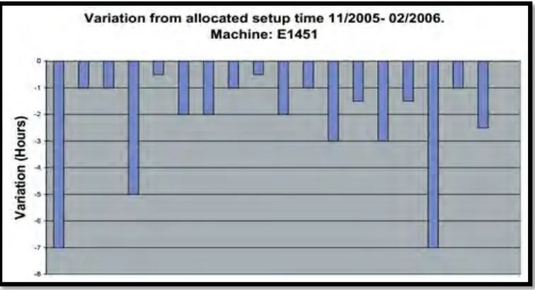
2.2.2 Setup time in injection molding
10 injection molding machine E802 produce the gat base in type of mold for about 8 minutes. Table 2.2.2 (c) shows that the task molds base changimg for injection molding machine E1451.