UNIVERSITI TEKNIKAL MALAYSIA MELAKA
TOOL WEAR PREDICTION BY MEASURING
CUTTING FORCE
2012
NIK NURFATHI NADIA BINTI NIK MUSTAFFA
UNIVERSITI TEKNIKAL MALAYSIA MELAKA
TOOL WEAR PREDICTION BY MEASURING CUTTING
FORCE
This report submitted in accordance with requirement of the Universiti Teknikal Malaysia Melaka (UTeM) for the Bachelor Degree of Manufacturing Engineering
(Manufacturing Process) (Hons.)
by
NIK NURFATHI NADIA BINTI NIK MUSTAFFA
B050810127
890304036094
UNIVERSITI TEKNIKAL MALAYSIA MELAKA
BORANG PENGESAHAN STATUS LAPORAN PROJEK SARJANA MUDA
TAJUK: Tool Wear Prediction by Measuring Cutting Force
SESI PENGAJIAN: 2011/12 Semester 2
Saya NIK NURFATHI NADIA BINTI NIK MUSTAFFA
Mengaku membenarkan Laporan PSM ini disimpan di Perpustakaan Universiti Teknikal Malaysia Melaka (UTeM) dengan syarat-syarat kegunaan seperti berikut:
1. Laporan PSM adalah hak milik Universiti Teknikal Malaysia Melaka dan penulis.
2. Perpustakaan Universiti Teknikal Malaysia Melaka dibenarkan membuat salinan
untuk tujuan pengajian sahaja dengan izin penulis.
3. Perpustakaan dibenarkan membuat salinan laporan PSM ini sebagai bahan
pertukaran antara institusi pengajian tinggi. 4. **Sila tandakan (√)
SULIT
TERHAD
TIDAK TERHAD
(Mengandungi maklumat yang berdarjah keselamatan atau kepentingan Malaysia yang termaktub di dalam AKTA RAHSIA RASMI 1972)
(Mengandungi maklumat TERHAD yang telah ditentukan oleh organisasi/badan di mana penyelidikan dijalankan)
Alamat Tetap:
Lot 910, Kg. Beta, Pohon Buluh,
Jln Meranti, 17000 Pasir Mas,
Kelantan Darul Naim.
Tarikh: 29th June 2012
Disahkan oleh:
Tarikh: 29th June 2012
APPROVAL
This report is submitted to the Faculty of Manufacturing Engineering of UTeM as a partial fulfillment of the requirements for the degree of Bachelor of Manufacturing Engineering (Manufacturing Process) (Hons.). The member of the supervisory is as follow:
DECLARATION
I hereby, declared this report entitled “Tool Wear Prediction by Measuring Cutting Force” is the results of my own research except as cited in references.
Signature : ………...
Author’s Name : NIK NURFATHI NADIA NIK MUSTAFFA
i Proses pemesinan seperti ‘turning’, ‘milling’, ‘drilling’, dan ‘grinding’ biasanya digunakan terutamanya dalam industri pembuatan. Mereka perlu mengeluarkan produk dalam jumlah yang banyak bagi mencapai target syarikat mereka. Masalahnya, bilakah mata alat perlu ditukar. Objektif utama kajian ini adalah menentukan hubungan di antara daya pemotongan dan kehausan mata alat dengan menggunakan ‘dynamometer’ dan mengkaji kesan kehausan mata alat terhadap permukaan yang tidak rata. Laporan kajian ini adalah bertujuan memberikan persembahan yang jelas tentang kehausan mata alat kepada industri. Skop kajian ini meliputi penyelidikan terhadap kehausan mata alat dan daya pemotongan dalam pemusingan titik tunggal dan kesan kehausan mata alat terhadap permukaan yang tidak rata dengan menggunakan mesin pemusingan konvensional. Sepanjang kajian ini, keluli lembut akan digunakan sebagai bahan eksperimen dan tungsten karbida sebagai mata pemotong. Fokus utama kajian ini juga adalah bagaimana untuk mengukur hubungan antara daya pemotong dan kehausan mata alat dengan menggunakan dynamometer. Berdasarkan eksperimen yang telah dibuat, keputusan telah menunjukkan bahawa, wujudnya perkaitan antara daya pemotong dan kehausan mata alat. Selain itu, keputusan juga menunjukkan ada perkaitan antara kehausan mata alat dan kekasaran permukaan dan juga perkaitan antara daya pemotong dan kekasaran permukaan.
ii Machining operations such as turning, milling, drilling and grinding are commonly used especially in manufacturing industry. These operations have to produce high volume of products in order to ensure companies’ targets are achieved. The problem is how to know when the cutting tool needs to be changed. The main objective of this study are to investigate the correlation between cutting force and tool wear by using the dynamometer, to study the effects and correlation of tool wear on surface roughness and to study the effects and correlation of cutting force on surface roughness. The purpose of this study is to provide clear presentation of the effect of tool wear to the industry. The scope of this study are including the study of tool wear and cutting force in the single point turning operation, and the effect of tool wear on surface roughness using conventional turning machine. During this study, the workpiece that used was mild steel and tungsten carbide was used as cutting tool. This study also focused on establishing the correlation between the cutting force and tool wear by using force dynamometer. Based on the experiment done, the results indicated that, there are some correlation between cutting force and flank wear. Besides, there were some correlation between flank wear and surface roughness and between cutting force and surface roughness.
iii To my beloved parents,
Mr. Nik Mustaffa Bin Che Daud and Mrs. Che Muji Binti Mohd
My beloved sister
And also
iv I am very thankful to Allah S.W.T as I finally finished my project paper with all His blessing and granting me with the strength and wisdom to face all the challenges during the accomplishment of this project. During finishing this project, there are so many obstacles that I have been through and all these experience are very useful to me in gaining the new knowledge’s.
Then, it is utmost pleasure that I would like to thank to Dr. Md. Nizam Bin Abd. Rahman, my most respective supervisor for Project Sarjana Muda. With his kindness, he gives his best guidance and assistance throughout my final year project and preparation of this report writing. I would like to lovely appreciate his willingness to spend some time with me while doing this project.
Other than that, my special thanks go to my parents, En. Nik Mustaffa Bin Che Daud and Puan Che Muji Binti Mohd who gave moral support and guidance. Also, special thanks go to all my friends who are helping me in completing this project. At last but not least, my thanks go to Faculty of Manufacturing Engineering, UTeM. I also would like to take this opportunity to thank to all lecturers who has taught me in Degree of Manufacturing Process courses throughout my study in Universiti Teknikal Malaysia Melaka.
Thank you.
v
TABLE OF CONTENT
Abstrak i
Abstract ii Dedication iii Acknowledgement iv
Table of Content v
List of Tables viii
List of Figures ix
List Abbreviations, Symbols and Nomenclatures xi
CHAPTER 1: INTRODUCTION 1
1.1 Background 1
1.2 Problem statement 2 1.3 Objectives 3 1.4 Scope of Study 3
1.5 Organization of Final Project 4
CHAPTER 2: LITERATURE REVIEW 5
2.1 The Lathe 5
2.2 Turning Processes 6
2.2.1 Single-point Cutting Tool 8
2.2.2 Tool Geometry 9
2.2.3 Cutting Tool Materials 11
2.3 Parameter That Affecting Surface Roughness 12
2.4 Tool Wear 14
2.4.1 Tool Wear Phenomena 15
2.4.1.1 Crater Wears 16
2.4.1.2 Flank Wear (Clearance Surface) 17
2.4.1.3 Notch Wear 18
2.4.1.4 Chipping 18
vi
2.4.1.6 Ultimate Failure 19
2.4.2 Causes of Tool Wear 20
2.4.2.1 Hard Particle Wear (Abrasive Wear) 20
2.4.2.2 Adhesive Wear Mechanism 21
2.4.2.3 Diffusion Wear 21
2.4.2.4 Oxidation Wear and Chemical Wear 22
2.4.2.5 Fatigue Wear 22
2.5 Effect of Tool Wear On Surface Roughness 22
2.6 Effect of Tool Wear On Cutting Force 23
2.7 How to Measure Cutting Force 23
2.8 How to Measure Tool Wear 24
2.9 How to Make Correlation Study 25
2.9.1 Pearson’s Moment 26
2.10 Summary 28
CHAPTER 3: METHODOLOGY 29
3.1 Project Planning 29
3.2 Material 31
3.2.1 Material of Workpiece 31
3.2.2 Material of Cutting Tool 32
3.3 Data Collected 33
3.4 Machining Experimentation 35
3.4.1 Cutting Condition 39
3.4.2 Method to Analyse the Surface Roughness 40
3.4.3 Method to Analyse the Tool Wear 41
3.4.4 Method to Measure the Cutting Force 43
3.5 Correlation Study 43
3.5.1 Scatter Plot 44
3.5.2 Microsoft EXCEL Software 44
3.5.3 Linear Regression 46
vii
CHAPTER 4: RESULTS & DISCUSSION 47
4.1 Data Collected 48
4.1.1 Cutting Force Data 49
4.1.2 Tool Wear Data 50
4.1.3 Surface Roughness Data 57
4.2 Summary of Data Taken 58
4.3 Correlation between Cutting Force and Flank Wear 59
4.4 Correlation between Flank Wear and Surface Roughness 61
4.5 Correlation between Cutting Force and Surface Roughness 64
CHAPTER 5: CONCLUSION & RECOMMENDATIONS 66
5.1 Conclusion 66
5.2 Recommendations 68
REFERENCES
APPENDICES
A Gantt Chart for PSM 1 B Gantt Chart for PSM 2
viii
LIST OF TABLES
2.1 The Standard Terminology for Geometry of Single Point Turning Tool (Venkatesh, 2009)
10
2.2 Parameters That Affect Surface Roughness in Turning (Khandey, 2009)
12
2.3 Parameters that Effect Surface Roughness 14
2.4 Recommended Wear Land Size for Different Tool Material and Operation (Amarego and Brown, n.d)
17
3.1 The Composition of Mild Steel (MS) 31
3.2 General Properties of Mild Steel (MS) 31
3.3 Sumitomo SPGN120308S Cutting Tool Dimensions 32
3.4 The Composition of Tungsten Carbide (WC) 33
3.5 General Properties of Tungsten Carbide 33
3.6 Data Collected 35
3.7 3.8
Several steps using the single point lathe machine
The function of Several Components in Lathe Machine 37 38 3.9 The Constant Cutting Parameters Based On ISO 3685 39
3.10 The Instruction to Use Microsoft EXCEL 45
4.1 Example of microscope image of the flank wear value for Workpiece 2
51
4.2 The collection of overall data 58
4.3 Cutting force and flank wear data 59
4.4 Flank wear and surface roughness data 62
ix
LIST OF FIGURES
2.1 The Engine Lathe is The Most Common Lathe Found in A Machine Shop (Krar et al. 2011)
6
2.2 Types of Cutting (a) Orthogonal and (b) Oblique Cutting (Astakhov et al. 2010)
7
2.3 Turning Process Involves Cutting and Feed Motion (Marinov, n.d)
8
2.4 Geometry of a Single Point Turning Tool (Khandev, 2009)
9
2.5 Different Modes of Wear (Hogmark and Olsson, n.d)
15
2.6 Tool Wear Phenomena (Khandev, 2009) 15
2.7 Crater Wear (Armarego and Brown, n.d) 16
2.8 Flank Wear (Armarego and Brown, n.d) 17
2.9 Notch Wear (Armarego and Brown, n.d) 18
2.10 Chipping of The Cutting Edge (Armarego and Brown, 2009)
19
2.11 Plastic Deformation (Armarego and Brown, 2009) 19 2.12 Ultimate Failure (Armarego and Brown, n.d) 20 2.13 Forces Acting on a Cutting Tool (Trent et al. 1977) 24 2.14 Flank Wear Estimation Methods (Adesta et al. 2010) 25
2.15 Types of correlation (Ferguson, 1974) 26
2.16 The Formula of Pearson’s coefficient (Ferguson, 1974)
27
3.1 Flow Chart of Methodology Process 30
3.2 Tungsten carbide cutting tool insert commercially made by Sumitomo
32
3.3 Process Flow of the Experiment 34
x 3.5 The Process Flow of Single Turning Lathe Machine 36
3.6 Portable Surface Roughness Tester 40
3.7 The Stereo Microscope Model Meiji EMZ-13TR 41
3.8 Measurement of Flank Wear 42
3.9 Kistler Dynamometer Type 9257B 43
3.10 Graph of Tool Wear, VB (mm) versus Cutting Force, Fc (N)
44
3.11 The perfect positive correlation graph 47
4.1 Example graph of cutting force from dynamometer before averaging
49
4.2 Example graph of cutting force from dynamometer after averaging
50
4.3 Examples data of surface roughness printed out from Portable Surface Roughness Tester
57
4.4 Graph of correlation between cutting force and flank wear before editing
60
4.5 Graph of correlation between cutting force and flank wear after editing
60
4.6 Graph of correlation between flank wear and surface roughness before editing
62
4.7 Graph of correlation between flank wear and surface roughness after editing
63
4.8 Graph of correlation between cutting force and surface roughness
xi
LIST OF ABBREVIATION, SYMBOLS AND
NOMENCLATURE
ap - Depth of Cut
BRA - Back Rake Angle
BUE - Build-up-edge
C - Carbon
CBN - Cubic Boron Nitride
Cr - Chromium
Cu - Copper
ECAC - End Cutting-edge Angle ERA - End Relief Angle
f - Feed Rate
Fc - Cutting Force
Ff - Feed Force
Fp - Passive Force
GPa - Giga Pascal
HSS - High Speed Steel HV - Hardness – Vickers ISO - International Standard
KB - Crater Width
KF - Crater Front Distance kg/m3 - kilogramme per metre cubic KM - Crater Centre Distance
KT - Crater Depth
L - Length
Mn - Manganese
Mo - Molybdenum
MPa - Mega Pascal
MS - Mild Steel
xii
Ra - Surface Roughness Average
RA - Side Rake Angle
re - Corner Radius
SCEA - Side Cutting-edge Angle
Si - Silicon
SRA - Side Relief Angle
UTeM - Universiti Teknikal Malaysia Melaka
V - Vanadium
VB - Width of Flank Wear
VBmax - Maximum Width of Flank Wear
1 This chapter contains the introduction and project background. Problem statements, objectives and scopes of this project are also discussed in this chapter. Meanwhile, there are chapter organisations that explain about overall chapter on this report.
1.1 Background
Turning is a material removal process, which produce cylindrical parts by removing away unwanted material. The cutting tool feeds into the rotating workpiece and removes away material in the form of small chips to manufacture the desired shape. The process usually applied using turning lathe machine and the majority of turning operations uses the simple single point cutting tool. In turning, the speed and motion of the cutting tool are commonly influenced through by several parameters such as cutting speed, depth of cut, cutting fluids and characteristics of the machine tool. The selection of the parameters for each operation will depend on the workpiece material, tool material, tool size and more (Kalpakjian et al. 2006).
In machining operations, the selection of cutting tool materials for a particular application is among the most important factors as is the selection of mold and die materials for forming and shaping processes (Kalpakjian et al. 2006). Only if the surface quality and the tolerances fall within the range of acceptance level, cutting tools can be used. Therefore, it must be replaced when a cutting tool reaches its life
2 before the cutting edge of the tool cannot produce the required surface roughness and the accepted tolerance (Adesta et al. 2010).
Wear is a gradual process, much like the wear of the tip of an ordinary pencil. The tool and workpiece materials, tool geometry, process parameters, cutting fluids, and the characteristics of the machine tool depending by the rate of tool wear. In all machining operations, these conditions induce tool wear, which is a major consideration, as are molded and die wearing in casting and metalworking. Tool life, the quality of the machined surface and its dimensional accuracy, and consequently, the economics of cutting operations adversely influences by tool wear (Kalpakjian et al. 2006).
1.2 Problem Statement
In industry, machining operation such as turning, milling, drilling and grinding commonly use especially in manufacturing industry. There need to produce high volume of products in order to ensure their company always achieve their target. The optimization of machining processes is necessary for the achievement of high responsiveness of production. However, it can cause wear on the tool. A result of physical interaction between the cutting tool and workpiece that removes small parts of material from the cutting tool is known as wear. Tool wear can cause catastrophic failure of the tool that causes considerable damage to the workpiece and even to the machine tool after a certain limit (Ertunc et al. n.d.).
3 predict tool wear. This can eliminate the needs to stop machining process to check for tool wear.
1.3 Objectives
The objectives of this study can be described as the following:
a) To investigate the correlation between the cutting force and tool wear by using the dynamometer.
b) To study the effects and correlation of tool wear on surface roughness. c) To study the effects and correlation of cutting force on surface
roughness.
1.4 Scope of Study
4
1.5 Organization of Final Project
The remainder of this thesis is compromised of five chapters as summarized below.
Chapter 1: The introduction of tool wear, its background and brief history and the significance of the project.
Chapter 2: A review of literature relevant to the present study of tool wear.
Chapter 3: This chapter explains the working procedure to execute the whole project.
Chapter 4: This section analysis and discusses the results that have been complete.
Chapter 5: Conclusions are drawn from the overall findings of the research along with recommendations for future work.
5 From the early stage of the project, various literature studies have been done. Research journal, reference books, printed or online conference article are the main sources of information for this literature review. The topics discussed in this chapter are the effect of tool wear and cutting force in turning operation and the correlation method.
2.1 The Lathe
Krar et al. (2011) stated that as a historical, all the machine tools pioneered by lathe machines. The first application of the lathe principle was probably the potter's wheel and this machine can change the mass of clay into a cylinder shape just by turning it.
Using the same basic principles, modern lathes run. The work carried out and rotates on its axis and at the same time, the tool moves on the line according to the user in determining what shape that need. This machine also can do processes such as turning, tapering, form turning, screw cutting, facing, drilling, boring, spinning, grinding, and polishing operations. All the processes can be done by using the lathe machine with appropriate equipment. Before started the process, cutting tool must be set first either parallel or perpendicular to the axis of the work while the angle relative to the work axis need to identify first in machining tapers and making the angles (Krar et al. 2011).
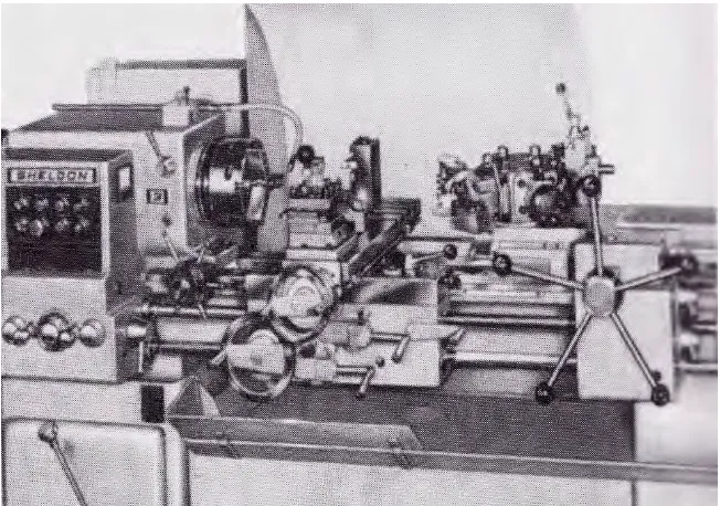
6 There are so many specials types of lathes appear due to development of modern production which are turret, single- and multiple-spindle automatic, tracer and numerically controlled lathes and the latest, computer-controlled turning centers. There is also one type of lathe that not use in production which called engine lathe. This type of lathe usually found in jobbing shops, school shops, and tool rooms (Krar et al. 2011). Figure 2.1 below shows the engine lathe.
Figure 2.1: The engine lathe is the most common lathe found in a machine shop (Krar et al. 2011).
2.2 Turning Processes
Machining is one of the most versatile processes in manufacturing industry in order to perform processing, shaping or cutting. Machining is the process where the workpiece is applied by a force in order to shape it. Using the machining process, variety of shapes can be produce (Kalpakjian and Schmid, 2006).