DESIGNING HELICOPTER CONTROLLER USING SOFWARE
NORSARIZAN BT MAT YOUB
“I hereby declared that I have read through this report and found that it has comply the partial fulfillment for awarding the degree of Bachelor of Electrical Engineering
(Control, Instrumentation & Automation)”
Signature : ...……… Supervisor,s Name : ALIAS BIN KHAMIS
DESIGNING HELICOPTER CONTROLLER USING SOFWARE
NORSARIZAN BT MAT YOUB
This Report Is Submitted In Partial Fulfillment Of Requirements For The Degree of Bachelor In Electrical Engineering
(Control, Instrumentation & Automation)
May 2008
“I hereby declared that this report is a result of my own work except for the excerpts that have been cited clearly in the references.”
Signature : ...……… Name : NORSARIZAN BT MAT YOUB
For my beloved father, Mat Youb Bin Hamzah ; Mum, Sabariah Bt Abd. Hamid ;
ACKNOWLEDGEMENTS
First of all, I would like to express my thankfulness and gratitude to Allah S.W.T who has given me all the strength that I needed to complete this final year project and also prepare this report.
With this opportunity, I would like to express my gratitude to the Faculty of electrical Engineering ( FKE ), Universiti Teknikal Malaysia Melaka (UTeM) generally, and especially to my supervisor Mr Alias Bin Khamis for this help, advices and guidance that he gave during this project.
And also to my parents, a million of thanks to them because of their support to me with their prayer and their love. Last but no least, I would like to thank all my friends 4BEKC whom have been such wonderful friends to me and also to everyone who was involved in the completion of this project. I would like to thank them for all support and encouragement to me which have given me the courage and wisdom to fulfill my final year project.
TABLE OF CONTENTS
CHAPTER TITLE PAGE
ACKNOWLEDGMENT i
ABSTRACT ii
ABSTRAK iii
TABLE OF CONTENTS iv
LIST OF TABLES vi
LIST OF FIGURES vii
LIST OF APPENDICES ix
1 INTRODUCTION 1.1 Definition 1
1.2 Project Overview 2
1.3 Problem statements 2
1.4 Objectives of the project 2
1.5 Scope of the project 3
2 LITERATURE REVIEW 2.1 Overview 4
2.2 Helicopter 4
2.3 MATLAB 10
2.4 Parallel Port Connection 15
CHAPTER TITLE PAGE
3 METHODOLOGY
3.1 Methodology of the project 20
3.2 System concept (GUI) 24
4 RESULTS AND DISCUSSION 4.1 Hardware Development 36
4.2 Software Development 43
4.3 Comparison 49
5 DISCUSSION AND RECOMMENDATION 5.1 Discussion 50
5.2 Recommendation 50
6 CONCLUSION 51
LIST OF REFERENCES 52
LIST OF TABLES
TABLE TITLE PAGE
2.1 Function of each connection 16
3.1 Function of creating the GUI 26
3.2 Important figure Properties(a) 28
3.3 Important figure Properties (b) 29
3.4 Selected Dialog Boxes 34
3.5 Important uimenu Properties 35
3.6 Important uicontextmenu Properties 35
4.1 Some Basic GUI Components 44
LIST OF FIGURES
FIGURE TITLE PAGE
2.1 Main rotor 5
2.1 Tail rotor 6
2.3 Lifting dissymmetry 7
2.4 Swash Plate Assembly 9
2.5 A DB-25 parallel printer port 15
2.6 A DB-25 parallel port connection 17
2.7 8-Bit Transmitter Schematic 18
2.8 8-Bit Receiver Schematic 19
3.1 Methodology flow chart 21
3.2 MATLAB Programming flow chart 22
3.3 Block diagram of the operation of helicopter controller 23
3.4 Detailed explaination of PC controller 23
4.1 Moving up circuit 36
4.2 Move left and right circuit 37
4.3 Moving down circuit 37
4.4 Stop circuit 38
4.5 Interfacing circuit 39
4.6 Controller circuit 39
4.7 Remote control 39
4.8 Set of all cicuit 40
4.9 Model of helicopter 40
4.10 Flow of step connection 40
FIGURE TITLE PAGE
4.12 Schematic diagram to inner equipments 42
4.13 Programming data 43
4.14 The guide tool window 45
4.15 Rough layout for a GUI containing a single pushbutton and a single label field. 46
4.16 The completed GUI layout within the guide window 46
4.17 The property inspector window 47
LIST OF APPENDICES
APPENDIX TITLE PAGE
A Helicopter model 52
B Optocoupler 53
C Transistor 56
CHAPTER I
INTRODUCTION
1.1 Definition
In the world of Radio Controlled Vehicles, RC stands for radio controlled but can also mean remote controlled. RC vehicles are scale model helicopters, cars, trucks, and other vehicles that are controlled by a hand-held controller that sends radio signals to the vehicle. Remote controlled is often meant to mean toy vehicles that have a line between the controller and vehicle but often the term remote controlled is used to mean an radio controlled RC.
2
1.2 Project Overview
The project has been divided into four main parts; hardware (transmitter), helicopter model, remote control and software (MATLAB). The computer is interfaced to a transmitter on the helicopter by a parallel connection. This helicopter in consist of 4 channel transmitter. It can simulate most flying attitudes of modem helicopter, such as hanging in the air, up and down and moving forwards and backward. This can use MATLAB software on personal computer directly to the helicopter compare to the use remote control. The ability to control the helicopter using by computer as well as remotely.
1.3 Problem statements High costs for maintenance
Control the helicopter for limited distance. Not suitable for commercial applications.
Difficult to protect the electrical equipment installed in the helicopter.
1.4 Objectives of the project
To design helicopter controller using MATLAB. To reduce cost in designing controller.
3
1.5 Scope of the project
The concept of remote control helicopter is an up-to-date high-tech product. It consists of three major sections. First, the helicopter mechanical structure including main rotor. Second, the electronic control equipment including battery, electronic mixed controller, and gyroscope. Lastly, the remote control unit including remote transmitter, receiver, and servo. It can simulate most flying attitudes of modem helicopter, such as hanging in the air, hanging in the air, up and down and moving forwards and backwards. Equipped with precision electronic gyroscope to stabilized flying posture and provide emulation flying effect.
4
CHAPTER 2
LITERATURE REVIEW
2.1 Overview
This chapter will discuss about source or article that related to the project. There have many sources or researches done before and from there, details about this project are known and can understand briefly about the software.
2.2 Helicopter
Helicopter lift is obtained by means of one or more power driven horizontal propellers which called Main Rotor. When the main rotor of helicopter turns it produces lift and reaction torque. Reaction torque tends to make helicopter spin. On most helicopters, a small rotor near the tail which called tail rotor compensates for this torque. On twin rotor helicopter the rotors rotate in opposite directions, their reactions cancel each other.
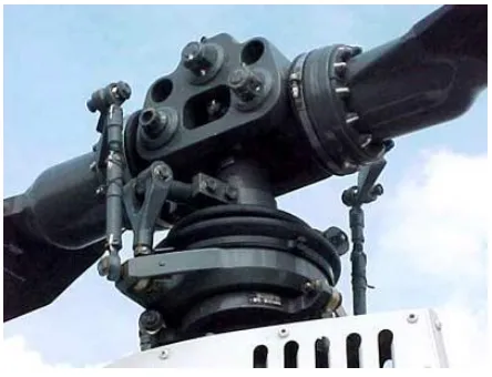
2.2.1 Main rotor
5
Figure 2.1: Main rotor
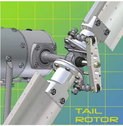
2.2.2 Tail rotor
6
[image:20.595.194.391.69.270.2]
Figure 2.2: Tail rotor
2.2.3 Lifting dissymmetry
All rotors are always experiencing Dissymmetry of Lift in forward flight. As the helicopter gain air speed, the advancing blade develops greater lift because of the increased airspeed and the retreating blade will produce less lift, causing the helicopter to roll. This has to be compensated for in some way. The compensation is mostly effectuated passively by blade flapping. Increased airspeed and lift on the advancing blade will cause the blade to flap up and decreasing the angle of attack. The decreased lift on the retreating blade will cause the blade to flap down and increasing the angle of attack. This combination equalizes the lift over the two halves of the rotor disc.
7
Figure 2.3 : Lifting dissymmetry
2.2.4 Regulating the force of the main or tail rotor.
This is usually done on a real helicopter by regulating the angle of the rotor blades without changing the speed of the rotors, thus giving the rotors more or less power. At the same time the force of the motor must be regulated up or down by adding or decreasing the gas given. In a helicopter, the force may be regulated by changing the speed of the rotors because the mechanical system used here is simpler.
2.2.5 Regulating the flying direction for the helicopter
8
2.2.6 The mechanical regulation of the rotor blade angles and tilting This is done by the following mechanism in a real helicopter.
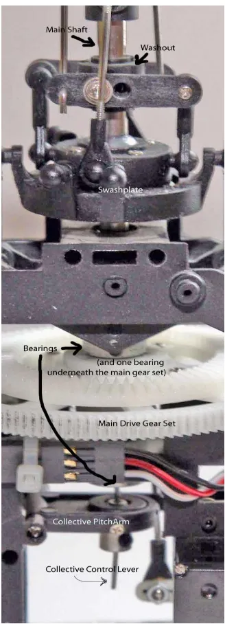
i. Swash Plate Assembly:
The swash plate assembly consists of two primary elements through which the rotor mast passes, one of which is a disc, linked to the cyclic pitch control. This disc can of tilt in any direction but does not rotate as the rotor rotates. This non-rotating disc is attached by a bearing surface to a second disc, often referred to as the which turns with rotor and linked to the rotor blade pitch horns.
ii. The Collective Control:
When pilot raises the collective control or pull collective control up , the collective control will raises the entire swash plate assembly as a unit . This has effect to the blades by changing the angle of all blades simultaneously. This causes to increase angle of attack and give more lift.
iii. The Cyclic Control:
9
10
2.3 MATLAB
MATLAB short for MATrix LABoratory is a special-purpose computer program optimized to perform engineering and scientific calculations. It started life as a program designed to perform matrix mathematics, but over the years it has grown into a flexible computing systems capable of solving essentially any technical problem.
The MATLAB program implements the MATLAB programming language, and provides an extensive library of predefined functions that make technical programming tasks easier and more efficient. This is introduces the MATLAB language and shows how to use it to solve typical technical problems.
MATLAB is a huge program, with an incredibly rich variety of functions. Even the basic version of MATLAB without any toolkits is much richer than other technical programming language.
2.3.1 Overview of MATLAB
MATLAB is a high-performance language for technical computing. It integrates computation, visualization, and programming in an easy to use environment where problems and solutions are expressed in familiar mathematical notation. Typical uses include
i. Math and computation ii. Algorithm development iii. Data acquisition
iv. Modeling, simulation, and prototyping v. Data analysis, exploration, and visualization vi. Scientific and engineering graphics