INVESTIGATION OF GRAVITY SEPARATION IN A
VERTICAL FLASH TANK SEPARATOR
A Thesis submitted by
Raid Ahmed Mahmood
For the award of
Doctor of Philosophy
Every challenging work needs self efforts as well as guidance of people especially those who are very close to our heart.
My humble effort, I dedicate to my loving, Father and Mother
Whose affection, endless love, support, encouragement and prayer of day and night make me able to get such success and honor.
My family
With special thanks to my son Abdullah, I can’t imagine how much pain you endured while you received the chemical treatment and fought the illness. My son Mahmood, my daughter Aeyah and my wife Iman each of whom has a special place in my heart.
Brothers and sisters
Abstract
Vapour injection through flash tank separation is an effective way to enhance the coefficient of performance (COP) and increase the capacity of air conditioning and re-frigeration systems. In rere-frigeration systems which use the vapour injection technique, the flash tank feeds the evaporator with refrigerant liquid and the vapour is delivered to the compressor. Hence, the vertical flash tank is an important component that can be used to improve the performance of air conditioning and refrigeration systems. Semi-empirical design methods based on settling theory can be used for flash tank de-sign, but the approach does not offer precise sizing data or an accurate assessment of likely performance under different operation conditions. Therefore, this thesis assesses the usefulness of CFD in flash tank design, and this is achieved through experiments and simulations on a range of relevant configurations using water as the working fluid. A new experimental facility was built and five different models of the vertical separator were used to investigate the effect of the aspect ratio (H/D) on the liquid separation efficiency for a range of mass flow rates from 2.1 to 23.4 g/s. The internal diameter of the separator in each case was 50 mm. The separation tank was fed with two-phase flow generated using an expansion device and a length of horizontal pipe of diameter 25 mm. The two-phase flow developed gradually after the expansion device, reaching the developed region at about 165 cm downstream.
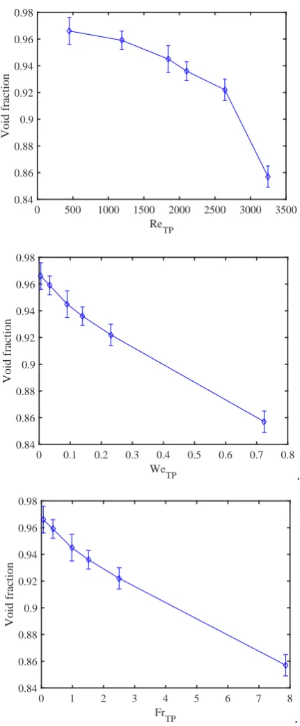
liquid separation efficiency of 0.99 was achieved by the last option at the maximum flow rate of 23.4 g/s. Empirical correlations were developed in horizontal pipe and vertical flash tank separator cases to predict the expansion length, void fraction and liquid separation efficiency. The range of the non-dimensional two-phase flow parame-ters covered by this study was: Reynolds number from 450.45 to 3246, Weber number from 0.005 to 0.72, and Froude number from 0.06 to 7.86.
CFD simulations were performed to simulate the two-phase flow within the horizon-tal tube which formed the inlet to the vertical separator, and the vertical separator itself. The simulations adopted the pressure based solver using the Eulerian-Eulerian multiphase model. In the horizontal tube case, the numerical results underestimated the expansion length in the experimental results with the simulated expansion length being an average of 8 % lower than the experimental observations. In the vertical tank separator case, the numerical results also underestimated the liquid separation efficiency in the experimental results with an average difference of the liquid separation efficiency of between 1 % and 2 %.
Certification of Thesis
This thesis is entirely the work of Raid Ahmed Mahmood except where otherwise ac-knowledged. The work is original and has not previously been submitted for any other award, except where acknowledged.
Principal Supervisor: Professor David Buttsworth
Associate Supervisor: Dr.Ray Malpress
Associate Supervisor: Dr.Ahmad Sharifian
First of all, I would like to thank My God and say Alhamdulillahi Rabbil Aalameen for getting healing for my son who was diagnosed with childhood cancer. It was a really hard challenge during the medical treatment.
I would like to express my sincere gratitude to my supervisor Professor David Buttsworth for the continuous support of my Ph.D study and related research, for his patience, motivation, and immense knowledge. His guidance helped me all the time. His insight and enthusiasm proved invaluable in the pursuit of new ideas and in the preparation of this thesis.
I would also like to thank Dr. Ray Malpress for his great technical support in the lab. My appreciation also goes to the technical staff in the Engineering workshop at University of Southern Queensland for their support, without their expertise and experience my conceptual ideas could never have been transformed into successful working realities.
I would like to thank my parents for their emotional and blessed support. All the sup-port they have provided me over the years was the most precious gift that anyone has ever given me. My sincere thanks go to my wife for her encouraging me to finish up my study. I would also like to acknowledge the support of the Australian Commonwealth Government for giving me an opportunity to complete this work.
Raid Ahmed Mahmood
University of Southern Queensland
Contents
Dedication i
Abstract i
Acknowledgments iv
List of Figures xiv
List of Tables xxvii
Notation xxx
Acronyms & Abbreviations xxxv
Chapter 1 Introduction 1
1.1 Value of flash tank separators . . . 1
1.2 Features of gravity separation . . . 4
1.3 Design and optimisation challenge . . . 7
1.5 Objectives of the thesis . . . 8
1.6 Overview of the thesis . . . 10
Chapter 2 Literature review 12 2.1 Introduction . . . 12
2.2 Configuration of vertical separators . . . 12
2.3 Flash tanks in vapour compression refrigeration systems . . . 13
2.4 Performance of vertical gas-liquid separators . . . 19
2.5 Vertical flash tank design using settling theory . . . 23
2.6 CFD studies of separators . . . 28
2.7 Conclusion . . . 30
Chapter 3 Basic definitions and terminology of two-phase flow 32 3.1 Introduction . . . 32
3.2 Definition of two-phase flow . . . 32
3.3 Vapour quality . . . 33
3.4 Volume flow rate . . . 34
3.5 Mass flux . . . 35
3.6 Velocities . . . 35
3.6.1 Average Local Velocity . . . 35
CONTENTS vii
3.7 Void fraction in two-phase flow . . . 37
3.8 Two-phase flow regimes in a horizontal tube . . . 39
3.9 Two-phase flow regimes maps . . . 43
3.10 Equations for regime transitions . . . 47
3.11 Two-phase pattern map for water . . . 50
3.12 Non-dimensional two-phase flow numbers . . . 51
3.13 Conclusion . . . 53
Chapter 4 Experimental apparatus 54 4.1 Introduction . . . 54
4.2 Apparatus layout . . . 55
4.3 Vacuum Condenser . . . 58
4.4 Expansion device . . . 64
4.5 Test sections . . . 67
4.5.1 Horizontal tube . . . 68
4.5.2 Vertical flash tank separator . . . 70
4.6 Vacuum pump . . . 72
4.7 Coil heat exchanger . . . 73
4.8 Adiabatic enclosure . . . 75
4.9 Flow visualisation technique . . . 77
4.10.1 Overview . . . 78
4.10.2 Mass flow rate meters . . . 79
4.10.3 Pressure transducers . . . 80
4.10.4 Temperature sensors . . . 80
4.10.5 Data Acquisition . . . 81
4.11 Analysis of Experimental uncertainty . . . 81
4.12 Operating conditions . . . 83
4.13 Conclusion . . . 85
Chapter 5 CFD Simulation 86 5.1 Introduction . . . 86
5.2 CFD Two-phase flow modelling approaches . . . 87
5.3 Computational domains . . . 89
5.3.1 Horizontal tube . . . 89
5.3.2 Vertical flash tank . . . 90
5.4 Boundary conditions . . . 91
5.4.1 Horizontal tube . . . 91
5.4.2 Vertical flash tank . . . 92
5.5 Mesh independence study . . . 93
5.5.1 Mesh quality . . . 93
CONTENTS ix
5.5.3 Vertical flash tank . . . 96
5.6 High performance computing facility . . . 97
5.7 Convergence . . . 98
5.8 CFD solver setting . . . 99
5.9 Conclusion . . . 100
Chapter 6 Two-phase flow development after expansion in a horizontal pipe 101 6.1 Introduction . . . 101
6.2 Development of two-phase flow after the expansion device . . . 102
6.3 Expansion length . . . 109
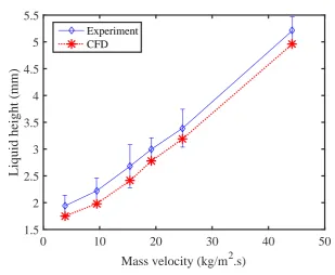
6.4 Liquid height in the developed region . . . 112
6.5 Void fraction analysis . . . 113
6.6 Local velocity and slip ratio . . . 115
6.7 Dimensionless Parameters . . . 116
6.8 Empirical correlation to identify the expansion region in a horizontal pipe.121 6.9 CFD simulation results . . . 123
6.9.1 Two-phase flow development on the bottom of the pipe . . . 123
6.9.2 Liquid height in developed region . . . 128
6.10 Length to fully-developed region . . . 130
Chapter 7 Two-phase flow in a vertical flash tank 133
7.1 Introduction . . . 133
7.2 Performance of the vertical flash tank . . . 134
7.3 Flow behaviour inside the vertical tank . . . 135
7.3.1 Experiments . . . 135
7.3.2 Numerical simulation . . . 141
7.4 Comparison of numerical and experimental results . . . 141
7.4.1 Effect of the mass flow rate . . . 141
7.4.2 Effect of the height . . . 145
7.4.3 Vapour quality at the vapour outlet . . . 146
7.5 Effect of d/D ratio . . . 148
7.6 Empirical correlation . . . 151
7.7 Conclusion . . . 156
Chapter 8 Enhancement of a vertical flash tank separator 157 8.1 Introduction . . . 157
8.2 Performance enhancement techniques . . . 158
8.3 Enhancement options . . . 159
8.4 Procedure of the CFD assessment . . . 159
8.5 Experimental arrangement . . . 159
CONTENTS xi
8.5.2 Operating conditions and measurements . . . 161
8.6 Design enhancements . . . 161
8.6.1 Extractor at the gas outlet of the VFT-V5 . . . 161
8.6.2 Inlet moved inside separator . . . 166
8.6.3 Change the direction of inlet flow . . . 169
8.6.4 Extractor at the outlet of VFT-V5-OD . . . 172
8.7 Comparison with the VFT-V5 baseline . . . 175
8.7.1 Liquid separation efficiency . . . 175
8.7.2 Vapour quality at the gas outlet . . . 177
8.7.3 Flow behaviour inside the separator . . . 178
8.8 Conclusion . . . 180
Chapter 9 Conclusions 181 9.1 Description of work . . . 181
9.2 Outcomes . . . 182
9.2.1 Two-phase flow in a horizontal pipe . . . 182
9.2.2 Liquid separation efficiency in the flash tank before enhancement 183 9.2.3 Enhancement of vertical separator . . . 184
9.3 Summary of conclusions . . . 185
References 186
Appendix A Drawings and design of apparatus 199
A.1 Condenser design and assembly . . . 199
A.2 Expansion device design . . . 206
A.2.1 Description of expansion device design . . . 206
A.2.2 Connection of the expansion device . . . 208
A.2.3 Pipe supporter clamp . . . 209
A.3 Vertical flash tank separator . . . 211
A.4 Experiment of a vertical separator . . . 213
Appendix B Instrument calibration 214 B.1 Pressure Transducer . . . 214
B.2 RTD calibration check . . . 216
B.3 Mass flow rate calibration . . . 217
Appendix C Experimental procedures 218 C.1 Procedures for horizontal pipe . . . 218
C.2 Procedures for flash tank . . . 220
Appendix D Vapour quality calculation 221
CONTENTS xiii
Appendix F Uncertainty analysis 225
F.1 Quantification of random errors — horizontal pipe . . . 225
F.2 Quantification of random errors — flash tank . . . 227
F.3 Uncertainty in measured parameters — horizontal pipe . . . 228
F.4 Uncertainty in vapour quality — horizontal pipe . . . 229
F.5 Uncertainty in void fraction — horizontal pipe . . . 230
F.6 Uncertainty in separation efficiency and quality — flash tank . . . 230
Appendix G Flash tank sizing calculation 233 Appendix H Fluent 17.1 key equations 235 H.0.1 Governing two-phase equations solved by fluent . . . 235
H.0.2 Turbulence model . . . 239
Appendix I Experimental results 243 I.1 Horizontal pipe experiments . . . 243
I.2 Vertical flash tank experiments . . . 244
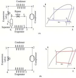
1.1 Schematic and P-h diagram of single stage compression refrigeration vapour injection system. (A) With a flash tank separator; (B) without a flash tank separator (Hanfei and Hrnjak 2012). . . 2
1.2 Schematic and P-h diagram of two stage vapour injection by using flash tank (Jang et al., 2010). . . 3
1.3 Schematic of the flash tank connection details in a refrigeration system (Hrnjak 2011). . . 5
1.4 Effect of inlet mass flow rate on the two-phase flow behaviour inside a vertical separator (Hrnjak 2011). . . 5
1.5 Different droplets size behaviour in a gravity separator (GPSA 2004). . 6
1.6 Vertical gravity separator showing a mist extractor (Arnold and Stewart 1998). . . 6
2.1 Flash tank in a two stage vapour compression system (Elbel and Hrnjak 2004). . . 14
LIST OF FIGURES xv
2.3 Vapour compression cycle with multi injection ports: (A) Schematic of multi injection system, (B) P-h diagram of system (Mathison et al. 2011). . . 15
2.4 Schematic of two stage vapour injection, a) Flash tank separator system, b) Internal heat exchanger system (Jang et al. 2010). . . 17
2.5 Heat pump system with flash tank: a) Schematic diagram of system, b) p-h diagram of heat pump system (Ma and Zhao 2010). . . 18
2.6 Flash tank and sub-cooler vapour injection air source heat pump (Heo et al. 2011). . . 19
2.7 Variation of liquid separation efficiency with inlet quality and mass flow rate for inlet diameter of 8.7 mm and body diameter 18.3 mm of T-junction gravity separator (Hanfei and Hrnjak 2012). . . 20
2.8 Photographs of flow at inlet quality 15 % and varied mass flow rates (Hanfei and Hrnjak 2012). . . 20
2.9 Variation of liquid separation efficiency with inlet quality and inlet in-clination angles at 30 g/s (Hanfei and Hrnjak 2012). . . 21
2.10 Photographs of flow showing effect of inlet inclination angle on the flow behaviour inside the vertical separator at 30 g/s mass flow rate and 15 % vapour quality (Hanfei and Hrnjak 2012). . . 21
2.11 Schematic of the heat pump system with flash tank investigated by Xu et al. (2011). . . 22
2.12 Typical flow patters in the horizontal tube inlet of a T-junction for different flow regimes: (A) Slug flow G = 100 kg/m2·s, xin = 0.073, (B) Stratified-wavy flowG= 100 kg/m2·s,xin=0.463, (C) Intermittent flowG= 400 kg/m2·s,xin = 0.372, (D) Annular flowG= 600 kg/m2·s,
2.13 Drag coefficient values for the rigid spheres (GPSA 2004). . . 26
3.1 Cross sectional void fraction . . . 37
3.2 Comparison of the logarithmic mean void fractionαLM with the Rouhani and Alxelsson void fractionαN H and homogeneous void correlationαH for R410A in circular tube with inside diameter d= 8 mm at mass flux
G=400 kg/m2·s, saturation temperatureT=40 (El Hajal et., 2003) . 39
3.3 Two-phase flow regimes during the evaporation process in a horizontal tube (Collier and Thome, 1994). . . 40
3.4 Flow regime classifications in a horizontal pipe at high void fraction (Dobson, 1994) . . . 42
3.5 Flow regime classifications in a horizontal pipe at low void fraction (Dob-son, 1994) . . . 43
3.6 Air-water two-phase flow pattern map for horizontal flow in tube by Baker (1954). . . 44
3.7 Air-water two-phase flow pattern map for horizontal flow in a tube by Mandhane et al. (1974). . . 45
3.8 Two-phase flow pattern map for R410A at Tsat=5 in a 13.84 mm diameter horizontal tube by Kattan et al. (1998). . . 46
3.9 Flow pattern map for R22 at Tsat = 5oC in the 13.84 mm test section diameter, evaluated at 100 kg/m2.s and 2.1 kW/m2 by Wojtan et al. (2005). . . 47
3.10 Stratified angle in two-phase flow (Thome 2003). . . 47
LIST OF FIGURES xvii
4.1 Schematic diagram of the expansion device and horizontal pipe experi-mental apparatus. . . 56
4.2 Schematic diagram of the vertical tank separator experimental appara-tus. . . 56
4.3 Photograph of the horizontal pipe experiment arrangement. . . 57
4.4 Photograph of the vertical separator experiment arrangement. . . 57
4.5 Schematic diagram of the condenser configuration and connection de-tails of the condenser. . . 59
4.6 Arrangement of the brass hose fittings around the PVC pipe. . . 59
4.7 Details of the flange combination connection to hold and seal the PVC and brass pipes (test section connection side). . . 60
4.8 Section view of the condenser (upstream test section connection side). . 61
4.9 Photograph of the condenser water pump. . . 62
4.10 Photograph of the condenser flanges and connections on the vacuum pump side. . . 63
4.11 Photograph of the condenser flanges and connections on the test section side. . . 63
4.12 Geometry of the expansion device and its section view. . . 64
4.13 Short control volume for analysis of the expansion device (a) Total length of the hole (b) Segment in two-phase region. . . 65
4.14 Configuration of the expansion device connection with the horizontal pipe test section. . . 68
4.16 Horizontal transparent acrylic pipe and special clamp. . . 70
4.17 Photograph of the vertical flash tank separator. . . 71
4.18 Arrangement of the vertical flash tank separator. . . 72
4.19 Connection of the vacuum pump with the condenser. . . 73
4.20 Photograph of the coil heat exchanger arrangement. . . 74
4.21 Adiabatic enclosure arrangement in the experiments: (a) Horizontal tube, (b) Vertical flash tank. . . 76
4.22 Photograph of the adiabatic enclosure around the horizontal tube. . . . 77
4.23 Photograph of cover and heat gun technique to control separator wall temperature. . . 78
4.24 Arrangement of the measurement instruments and experimental appa-ratus in the vertical separator case. . . 79
5.1 Computational domain of the horizontal tube geometry. . . 89
5.2 Computational domain of the vertical flash tank geometry. . . 90
5.3 Horizontal tube mesh with inflation near the wall for the 199356 element mesh case. . . 94
5.4 Assessment of grid independence for the horizontal tube showing vari-ation of the expansion length with the number of mesh element for operating condition case 6. . . 94
LIST OF FIGURES xix
5.6 Vertical flash tank mesh with inflation near the walls for the 220000 element mesh case. . . 96
5.7 Assessment of grid independence for the vertical flash tank showing variation of liquid separation efficiency with number of mesh element for operating condition case 5. . . 97
5.8 Configuration of the HPC of the University of Southern Queensland. . 98
6.1 Development of two-phase flow after expansion: (a) image from present experiments ( ˙m = 5.1 g/s and x = 5.7 %), (b) features impacting two-phase flow development after expansion device adapted from Hrnjak (2004). . . 103
6.2 Homogeneous flow (mixed flow) region of two-phase flow directly after the expansion device (flow direction from left to right). . . 103
6.3 Stratified flow at 1600 mm from the inlet, ˙m = 10.2 g/s and x = 5.4% (flow direction from left to right). . . 104
6.4 Sequential frames to illustrate liquid droplet movement from top to bot-tom of the pipe between 150 mm and 300 mm from the inlet ( ˙m= 13.1 g/s andx = 5.4 %, flow direction from left to right). . . 105
6.5 Sketch for droplet trajectory during the movement from the top to the bottom of the pipe. . . 106
6.6 Sequential frames to illustrate the observed liquid droplets merging be-tween 275 mm and 300 mm from the inlet, ˙m = 10.2 g/s and x = 5.4 %, flow direction from left to right. . . 106
6.8 Images of the two-phase flow at different mass flow rates at the down-stream end of the pipe. Images extend from 1500 mm to 1800 mm from the inlet, flow direction from left to right. . . 108
6.9 Observed liquid droplet movement from top to bottom of the pipe at locations from 150 mm to 300 mm from the inlet, ˙m = 13.1 ±0.2 g/s,
x = 5.4 %. . . 109
6.10 Image showing liquid film formation at the bottom of the pipe at loca-tions from 0 mm to 300 mm from the inlet, ˙m = 8.1±0.2 g/s,x= 5.5 %). . . 110
6.11 Length of the expansion region from the inlet of tube based on criteria 1: phase separation at the top of the pipe. . . 111
6.12 Length of the expansion region from the inlet of tube based on criteria 2: phase separation at the bottom of the pipe. . . 111
6.13 Illustration of the definition of liquid height and vapour in the developed region. . . 112
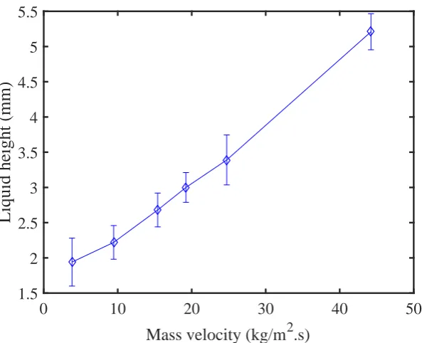
6.14 Variation of liquid height with mass velocity at 300 mm from the inlet. 113
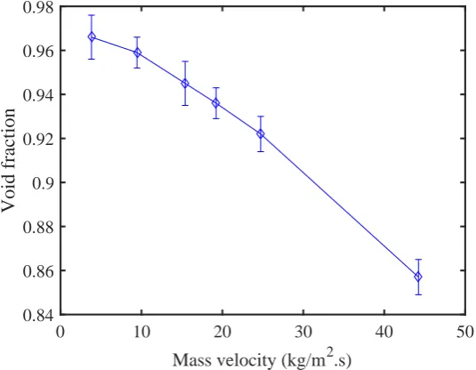
6.15 Relationship between the void fraction and the mass velocity in the developed region at 1665 mm from the inlet. . . 114
6.16 Variation of liquid height in the developed region with slip ratio =uv/ul at 1665 mm from the inlet. . . 115
6.17 Variation of the void fraction with the slip ratio in the developed region at 1665 mm from the inlet. . . 116
LIST OF FIGURES xxi
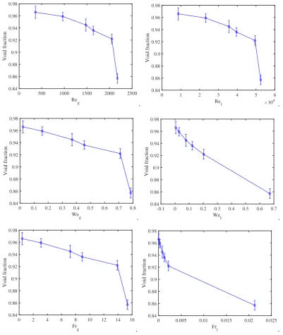
6.19 Void fraction in the developed region as a function of two-phase dimen-sionless numbers. . . 118
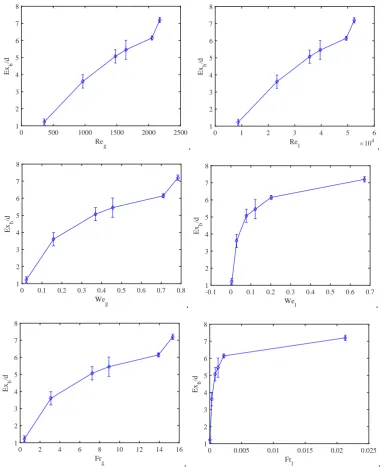
6.20 Expansion length at the bottom divided by diameter of the horizontal tube according to criteria 2 (liquid formation at the bottom of the pipe) as a function of liquid and gas dimensionless numbers. . . 119
6.21 Expansion length at the bottom divided by diameter of the horizontal tube according to criteria 2 (liquid formation at the bottom of the pipe) as a function of two-phase dimensionless numbers. . . 120
6.22 Comparison between the predicted and observed values of the nor-malised expansion lengthExb/dat the bottom of the pipe. . . 122
6.23 Comparison between the predicted and observed values of void fraction
α in the developed region in the horizontal pipe. . . 122
6.24 Liquid volume fraction (LVF) for ˙m= 23.4 g/s (a) LVF along the axial vertical plane; (b) LVF at 5 cm from the inlet; (c) LVF at 10 cm from the inlet; and (d) LVF at 20 cm from the inlet. . . 124
6.25 Liquid volume fraction along the axial vertical plane at the different operating conditions. . . 124
6.26 Contours of liquid volume fraction showing liquid formation at the bot-tom of the pipe on the axial vertical plane for ˙m = 5.1 g/s. . . 125
6.27 Contour lines of liquid volume fraction showing liquid formation at the bottom of the pipe on the axial verical plane ˙m= 5.1 g/s. . . 126
6.28 Zoomed-in view of contour lines of liquid volume fraction showing liquid formation at the bottom of the pipe on the axial vertical plane ˙m= 5.1 g/s. . . 126
6.30 Liquid height identification on the central vertical plane of the pipe at 1665 mm from the inlet, according to the liquid volume fraction definition for ˙m= 13.1 g/s. . . 128
6.31 Liquid volume fraction on the vertical planes perpendicular to the flow direction at 1665 mm from the inlet for the different operation condi-tions. . . 129
6.32 Comparison between the experimental data and numerical simulations for the liquid height on the central vertical plane of the pipe at 1665 mm from the inlet. . . 130
6.33 Simulated value of film height along the horizontal pipe based on differ-ent LVF values showing the expansion region length (LF D) for ˙m= 5.1 g/s. . . 131
6.34 Simulated values of the distance to the fully-developed region in the horizontal pipe for different inlet mass velocities. . . 131
7.1 Photograph showing observed liquid film on the vertical wall of the separator and liquid droplets distributed mostly towards to the bottom of the separator (VFT-V2 at 23.4 ±0.2 g/s). . . 136
7.2 Observed two-phase flow in vertical flash tank separator VFT-V1. Inlet flow direction from left to right. . . 136
7.3 Observed two-phase flow in vertical flash tank separator VFT-V2. Inlet flow direction from left to right. . . 137
7.4 Observed two-phase flow in vertical flash tank separator VFT-V3. Inlet flow direction from left to right. . . 138
LIST OF FIGURES xxiii
7.6 Observed two-phase flow in vertical flash tank separator VFT-V5. Inlet flow direction from left to right. . . 140
7.7 Numerical and experimental results for liquid separation efficiency with VFT-V1. . . 142
7.8 Numerical and experimental results for liquid separation efficiency with VFT-V2. . . 143
7.9 Numerical and experimental results for liquid separation efficiency with VFT-V3. . . 143
7.10 Numerical and experimental results for liquid separation efficiency with VFT-V4. . . 144
7.11 Numerical and experimental results for liquid separation efficiency with VFT-V5. . . 144
7.12 Comparison of experimental results for liquid separation efficiency for the various separators as a function of inlet mass velocity. . . 145
7.13 Comparison of numerical results for liquid separation efficiency for the various separators as a function of inlet mass velocity. . . 146
7.14 Vapour quality at the vapour outlet of the vertical flash tank separator. Results derived from experimental data. . . 147
7.15 Configuration of model geometries with d/D= 0.25, 0.5 and 1. . . 149
7.16 Comparison of numerical results showing the effect ofd/D ratio. . . 150
7.17 Liquid separation efficiency as a function of dimensionless numbers. . . . 152
7.19 Comparison between the predicted value and the observed results of the liquid separation efficiency. . . 155
8.1 Typical inlet diverter and mist extractor in a vertical separator, adapted from Campbell (2014). . . 158
8.2 Inlet pipe supporter with O-ring grooves. . . 160
8.3 Dimensions and illustration of the extractor. . . 162
8.4 Configuration of VFT-V5-EXR: (a) section view from 3d model, (b) photograph of the assembly. . . 162
8.5 Comparison between CFD and experimental results for VFT-V5-EXR. 163
8.6 Impingement of droplets coalescence, and detachment. (a) sequence of frames showing a liquid drop falling; (b) sketch illustrating the key processes in the extractor. . . 164
8.7 Images of the modified vertical flash tank separator VFT-V5-EXR dur-ing operation. Inlet flow direction from left to right. . . 165
8.8 Configuration of VFT-V5-INT: (a) section view from 3d model; (b) photograph of the assembly. . . 166
8.9 Comparison between CFD and experimental results for VFT-V5-INT. . 167
8.10 Images of the modified vertical flash tank separator VFT-V5-INT during operation. Inlet flow direction from left to right. . . 168
8.11 Configuration of VFT-V5-OD: (a) section view from 3d model; (b) pho-tograph of the assembly. . . 169
8.12 Comparison between CFD and experimental results for VFT-V5-OD. . 170
LIST OF FIGURES xxv
8.14 Configuration of VFT-V5-ODEXR: (a) section view from 3d model; (b) photograph of the assembly. . . 172
8.15 Comparison between CFD and experimental results for VFT-V5-ODEXR. . . . 173
8.16 Images of the modified vertical flash tank separator VFT-V5-ODEXR during operation. Inlet flow direction from left to right. . . 174
8.17 Experimental results comparing the VFT-V5 and the enhanced design configurations. . . 176
8.18 CFD results comparing the VFT-V5 and the enhanced design configu-rations. . . 176
8.19 Experimental results for the vapour quality at the gas outlet of the separator for the different configurations. . . 177
8.20 Images presenting a comparison of the flow behaviour inside the vertical separator for the different enhancement configurations at ˙m= 10.2±0.2 g/s. . . 179
A.1 Configuration of the vacuum condenser and its connections. . . 199
A.2 Schematic diagram of the O-ring flange. . . 200
A.3 Condenser vacuum side showing the location of the O-ring and flange combination. . . 201
A.4 Schematic diagram of the end plate flange and its dimensions. . . 202
A.5 Schematic diagram of the retaining flange and its dimensions. . . 202
A.6 Combination of the flange connection around the brass pipe. . . 203
A.8 Aluminium sealing flanges to connect the PVC pipe and the brass pipe. 204
A.9 Details of the flange combination connection to hold and seal the PVC and brass pipes on the test section connection side. . . 205
A.10 Section view of the condenser on the upstream test section connection side. . . 206
A.11 Expansion device (a) section view of the expansion device, (b) photo of 3D printed device. . . 207
A.12 Assembly of the horizontal test section tube, expansion device and nee-dle valve with PVC end cup. . . 208
A.13 Special supporter clamp (a) views of the supporter clamp, (b) 3D view, (c) photo of 3D printed clamp. . . 210
A.14 Vertical flash tank separator (a) Aluminium flange for top and bottom of the tank, (b) illustration of the VFT-V3 separator. . . 212
A.15 Arrangement of the main parts of the experiment on the vertical sepa-rator. . . 213
B.1 Photograph of the hydraulic dead-weight tester Budenberg model 580. 215
B.2 Comparison of temperature reading between the mercury thermometer and RTD temperature sensor. . . 216
C.1 Experimental arrangement for the horizontal pipe experiment. . . 219
List of Tables
2.1 Correlation of drag coefficient for spherical droplet for Yan et al. (2017), adopted from Zhou (2013). . . 26
4.1 Dimensions of the experimental geometries. . . 72
4.2 Power consumption and outlet temperature from the heat exchanger for the range of mass flow rates. . . 74
4.3 Specifications of mass flow rate meters. . . 80
4.4 Specifications of pressure transducers (Wika, 2011). . . 80
4.5 Manufactures’ designated uncertainty of the measurement instruments. . 82
4.6 Experimental boundary conditions in horizontal tube. . . 84
4.7 Experimental boundary conditions in vertical flash tank separator. . . . 85
5.1 The turbulence model compatibility with the multiphase model from FLUENT (2012). . . 88
5.2 Boundary conditions in horizontal tube simulations. . . 92
7.1 Dimensions of the model geometries for investigation of thed/D ratio. 148
A.1 Data on the VisiJet crystal plastic material. . . 208
B.1 Calibration of Wika pressure transducers. Vmeas= measured voltage, L.P. lower pressure, and H.P. high pressure. . . 215
F.1 Measurements of liquid height in the fully developed region for the range of mass flow rates. . . 226
F.2 Measurements of mass flow rates of vertical flash tank VFT-V1 at op-erating condition 2.1 g/s. . . 227
F.3 Measurements of mass flow rates of vertical flash tank VFT-V3 at op-erating condition 8.1 g/s. . . 227
F.4 Sample of experimental uncertainty calculation of measured quantity in the horizontal pipe experiments for case 1. . . 229
F.5 Sample of void fraction uncertainty calculation for 2.1 g/s. . . 230
F.6 Sample of results for vapour quality uncertainty calculation for the gas outlet of the vertical flash tank separator. . . 231
F.7 Sample of separation efficiency uncertainty calculation for the vertical flash tank separator. . . 231
F.8 Sample of experimental uncertainty of measured quantities in the verti-cal flash tank separator experiments for case 1. . . 232
I.1 Experimental result from the horizontal pipe experiments for the range of mass flow rates. . . 243
LIST OF TABLES xxix
I.3 Experimental liquid separation efficiency from the vertical flash tank separator experiments for the range of mass flow rates. . . 244
I.4 Experimental vapour quality at the gas outlet from the vertical flash tank separator experiments for the range of mass flow rates. . . 245
I.5 Experimental liquid separation efficiency from the vertical flash tank separator (enhancement design options) experiments for the range of mass flow rates. . . 245
Roman symbols
A Total cross sectional area, m2
Ag Area occupied by gas, m2
AL Area occupied by liquid, m2
AsF T Aspect ratio of the flash tank (H/D)
cp Specific heat, J/kg.K
D Inside diameter of separator, m
d Inside diameter of tube, m
dd Diameter of the secondary phase (bubble or droplet), m
dm Droplet diameter, m
Ex Expansion region length, m
f Drag coefficient
Fq External body force, N
Flif t,q Lift force, N
Fvm.q Virtual mass force, N
F r Froude number
H Height of the flash tank, m
HV Height of the vapour phase in the horizontal tube, m
h1,2,3,4,.. Enthalpy, kJ/kg ¯
hc Heat transfer coefficient inside tube, W/m2K
hLd dimensionless vertical height of liquid
ID inside tube diameter, m
NOTATION xxxi
Gg Vapour mass flux, kg/m2·s
Gl Liquid mass flux, kg/m2·s
g Acceleration of gravity, taken as 9.81 m/s2
Gr Grashof number
K Separation factor, m/s
k Thermal conductivity, W/m.K
kpq Inter-phase momentum coefficient
kqp Inter-phase momentum coefficient
L Length, m
mpq Mass transfer from phasep to phaseq, kg/s
mqp Mass transfer from phaseq to phase p, kg/s ˙
mg Vapour mass flow rate, kg/s ˙
ml Liquid mass flow rate, kg/s ˙
mLoutlet Liquid mass flow rate at the liquid outlet of the separator, kg/s ˙
mLinlet Liquid mass flow rate at the inlet of the separator, kg/s ˙
mt Total mass flow rate of mixture, kg/s
N u Nusselt number
P Pressure, kPa
Pid Dimensionless perimeter of interface
Pr Prandtl number
qc Heat transfer from tube surface to working fluid, W
Ql Liquid volume flow rate, m3/s
Qt Total volume flow rate, m3/s
Qv Vapour volume flow rate, m3/s
Qq Volume flow rate of phaseq, m3/s
Re Reynolds number
Rpq Interaction force between phases, N
S Slip velocity
Sq Mass source for each phase
T Temperature,
u Velocity, m/s
ul Liquid local velocity, m/s
usl Liquid superficial velocity, m/s
ust Total superficial velocity, m/s
uv Vapour local velocity, m/s
~
Up Phase weighted velocity of phase p, m/s
~
Uq Phase weighted velocity of phase q, m/s
UT Terminal velocity, m/s
Uv Vertical velocity, m/s
v Kinematic viscosity, m2/s
Vq Volume of phaseq, m3
~vq Velocity of phase q, m/s
W e Weber number
x Vapour quality
Greek symbols
α Void fraction
β Chord angle
B Coefficient of thermal expansion
µg Vapour dynamic viscosity, m2/s
µl Liquid dynamic viscosity, m2/s
µwater Liquid dynamic viscosity, m2/s
ρair Air density, kg/m3
ρg Vapour density, kg/m3
ρl Liquid density, kg/m3
ρwater Water density, kg/m3
ψ Liquid phase parameter (dimensionless)
ηL Liquid separation efficiency
τp Particulate relaxation time, s
τq Stress-strain tensor of q phase
τt,pq Lagrangian integral time scale
θ Angle
NOTATION xxxiii
λq Shear of phase q, N/m
σ Surface tension, kg/s2
Subscripts
b Bottom
g Vapour phase
H Homogeneous
i inside
in inlet
l Liquid phase
LM Mean logarithmic
N H Non-homogeneous
o outside
out outlet
s surface
t Top
T P Two-phase
F T Flash tank
Superscripts
Acronyms & Abbreviations
A Annular flow
AsF T Aspect ratio of the flash tank
ASHRAE American Society of Heating, Refrigerating and Air-Conditioning En-gineers, Inc.
CFD Computational Fluid Dynamics COP Coefficient of performance of cycle
CV Control volume
DAQ Data acquisition
EEV Electronic expansion valve
FGB Flash Gas Bypass
FT Flash tank
HPC High performance computer
I Intermittent flow
IHX Internal heat exchanger
LMTD Log mean temperature difference
M Mist flow
MPEG Format of video recording
NI National Instrument
PI Pi theorem
RSM Reynolds stress model
S Stratified flow
SW Stratified-wavy flow
SST Shear stress transport
Introduction
1.1
Value of flash tank separators
Air-conditioning, refrigeration and heat pump systems are used widely in domes-tic and commercial sectors and these systems use similar components (Mohanraj et al., 2009; Rasmussen, 2011). Much research is devoted to enhancing the main components of mechanical refrigeration systems such as compressors, fans and heat exchangers, and other work investigates cycle performance and attempts to reduce en-ergy consumption. The vapour injection technique using a flash tank is an effective way to enhance the system’s coefficient of performance (COP) (Elbel and Hrnjak, 2004). In refrigeration systems which use a vapour injection technique, a flash tank feeds the evaporator with the separated liquid, and the vapour is injected into the compressor (Ma and Zhao, 2008).
2 Introduction
17 % relative to a non-injected system in their working conditions. The flash tank feeds the evaporator with just refrigerant liquid and passes the vapour portion of the flow to the suction line of the compressor (Hanfei and Hrnjak, 2012).
[image:40.595.152.404.374.632.2]Figure 1.1 (A) shows a single stage vapour compression refrigeration system and as-sociated P-h diagram to show the thermodynamic processes when using a flash tank separator, and Figure 1.1 (B) shows the same system and its thermodynamic processes without the flash tank. The evaporator in Figure 1.1 (A) receives only saturated liquid from the flash tank so, the enthalpy at the inlet of the evaporator is much lower than that in Figure 1.1 (B) in which a mixture is delivered to the evaporator. This does not directly lead to enhanced performance because the mass flow rate through the evaporator is reduced if a flash tank system is used. Instead, the system performance will be increased through more subtle effects: increased heat transfer coefficient and reduced pressure drop in the evaporator (Elbel and Hrnjak, 2004).
Figure 1.1: Schematic and P-h diagram of single stage compression refrigeration vapour
injection system. (A) With a flash tank separator; (B) without a flash tank separator
In two-stage compression refrigeration systems, flash tanks can also be used to work as intercoolers or economizers as shown in Figure 1.2 (Jang et al., 2010). This technique is used to increase the cooling capacity and system performance of two stage systems by injecting vapour at an intermediate point in the compression processes and using a second expansion device to provide low enthalpies at the evaporator inlet as shown in process (7-8) in Figure 1.2. Under certain conditions these additions can increase the coefficient of performance to 10 % more than a system without a flash tank (Jang et al., 2010). Ma and Zhao (2010) indicate that the refrigeration system’s coefficient of performance can be increased up to 17 % by using a flash tank.
P
(k
P
a
)
1 2
4 5
7
8
6 3
Figure 1.2: Schematic and P-h diagram of two stage vapour injection by using flash tank
4 Introduction
Sirwan et al. (2013) reported that when a flash tank is used to feed the evaporator with liquid only, the coefficient of performance and system capacity will be increased due to an increase in the liquid fraction, a decrease in vapour quality at the inlet of the evaporator, and an increase in heat transfer coefficient at the inlet of the evaporator. Shuxue and Guoyuan (2014) conducted an experimental study to confirm that the flash tank is an effective addition that can increase the coefficient of performance by 10-12 % and system capacity by 5-15 %.
1.2
Features of gravity separation
Refrigerant flow from condenser
Refrigerant flow to compressor
Expansion device
Flash tank
Evaporator Flash gas bypass valve
Figure 1.3: Schematic of the flash tank connection details in a refrigeration system (Hrnjak
2011).
G=504.6 kg/m2.s x=5% G=168.2 kg/m2.s
x=5% G=336.4 kg/m
2.s
x=5%
Figure 1.4: Effect of inlet mass flow rate on the two-phase flow behaviour inside a vertical
separator (Hrnjak 2011).
6 Introduction
Figure 1.5: Different droplets size behaviour in a gravity separator (GPSA 2004).
Finally, the third feature of the vertical gravity separator is the mist elimination or mist extraction. It is a significant part of the separator, affecting droplets which are typically less than 10µm (GPSA, 2004). It separates these droplets from the gas phase before the vapour leaves the separator as shown in Figure 1.6 (Arnold and Stewart, 1998). Khorshidi and Naderipour (2012) suggested that the height of a gas-liquid vertical separator can be increased if an eliminator needs to be used but sometimes this may result in unreasonably high separators which are not economic. The small droplets are better coalesced in the mist extractor which operates via an impingement effect.
1.3
Design and optimisation challenge
In addition to the aspects introduced in section 1.2, to design an effective gravity flash tank separator for a mechanical refrigeration system, the aspect ratio of the flash tank should be considered (Mo et al., 2014). Refrigeration system performance can be impaired as a result of decreasing the separation efficiency when the size of the flash tank is not suitable to feed liquid to the evaporator and bypass the vapour to the compressor. Xu and Pham (2012), Hwang et al. (2010) and Heo et al. (2010) used a flash tank volume of 240 cm3 in a 3.6 kW air conditioning system, but the separa-tion performance and size optimizasepara-tion were not discussed. The sizing of a flash tank needs to be appropriate for the system capacity in order to obtain optimum system operation.
Several studies have investigated the design of the vertical separator such as Delgado and Pichardo (1999), Elbel and Hrnjak (2004), and Wiencke (2011), and these studies used settling theory, but uncertainty remains in determining likely range of droplet size, the droplet drag coefficient and the associated separation coefficient. Some stud-ies report recommendations for the design the vertical separator; for example, Seader et al. (1998) suggested a range for the separation coefficient, Stanly and Walas (1990) suggested a range for the droplet size, and Zhou (2013) listed some correlations for estimating the drag coefficient.
8 Introduction
studies.
1.4
Water as a refrigerant
Water is a natural refrigerant that can be used in refrigeration and air conditioning systems. Water represents the ultimate environmentally friendly refrigerant because it has a zero ozone depletion potential (ODP), zero global warming potential (GWP), and it is non-toxic and non-flammable (Wang et al., 2009). Therefore, water is clas-sified as a safe refrigerant, falling into the A1 group with a refrigerant code of R718 (Kilicarslan and M¨uller, 2005). Water also has excellent chemical and thermodynamic properties such that it can be used below its normal freezing point, and above its nor-mal boiling point, if it is mixed with appropriate solutions such as propylene glycol or ethylene glycol (Kilicarslan and M¨uller, 2005).
Water (R718) has been used in a wide variety of air conditioning and refrigeration ap-plications and has received renewed attention as a natural refrigerant after the signing of the Montreal Protocol to reduce the environmental concerns (Wang et al., 2009). Water has a long history of having been used in adsorption, absorption, desiccant, and ejector-based refrigeration and air conditioning systems. New and improved water-based refrigeration systems are currently under development. Therefore, having de-sign tools that can be applied with confidence to the associated two-phase fluid-flow problems is important.
1.5
Objectives of the thesis
1. Design and operate an appropriate water vapour vacuum system with a heat exchanger adequate for the two-phase flow investigations in a vertical flash tank.
2. Conduct an experimental investigation of two-phase flow development after an expansion device in a horizontal pipe.
3. Conduct an experimental investigation of the aspect ratio effect on the vertical flash tank performance.
4. Perform an experimental investigation of the proposed design enhancement op-tions to improve the separation efficiency of a vertical flash tank.
5. Perform computational simulations of two-phase flow using computational fluid dynamics CFD in the horizontal tube and vertical flash tank experiments.
10 Introduction
1.6
Overview of the thesis
This section describes the structure of the work which is presented in this thesis. The thesis is arranged as following.
Chapter 2 Literature review
Various theoretical and experimental studies using gravitational vertical flash tank separators with application in air conditioning, refrigeration and heating are reviewed.
Chapter 3 Basic definitions and terminology of two-phase flow
The fundamentals of two-phase flow and definitions of the main variables are presented in this chapter.
Chapter 4 Experimental apparatus
This chapter introduces the design of the experimental apparatus and its com-ponents. A unique design of the experimental apparatus was used to achieve the two-phase flow experiments using water as the working fluid. Operating conditions of the experimental apparatus are presented, and the measurement methods and their arrangement are presented.
Chapter 5 CFD Simulation
The computational fluid dynamics (CFD) methods used to simulate the two-phase flow development in a horizontal tube and the performance of the vertical flash tank separator are presented in this section. Eulerian-Eulerian multiphase model and standardk-turbulence model was used in the numerical simulation.
Chapter 7 Two-phase flow in a vertical flash tank
This chapter presents the investigation of the liquid separation efficiency of ver-tical flash tank separators having different aspect ratios and operated at different inlet mass flow rates. CFD simulations were also performed on these configura-tions and results were assessed against the experiments. An empirical correlation for the liquid separation efficiency was developed from the experimental results.
Chapter 8 Enhancement of a vertical flash tank separator
In this chapter, design options that improve the liquid separation efficiency of one particular separator are presented. A CFD simulation was performed to predict the performance of the enhancement design options before proceeding to the experiments and the numerical and experimental results were compared.
Chapter 9 Conclusions
Chapter 2
Literature review
2.1
Introduction
The function and use of vertical flash tank separators in chilling systems need to be considered to provide a suitable design. In order to design and optimize a vertical flash tank separator, a clear understanding of the two-phase flow development and associ-ated phenomena in the inlet tube and vertical flash tank separator need to be obtained. Therefore, in this chapter, various theoretical, experimental and computational studies relating to vertical separation and vertical flash tank design, the performance of ver-tical flash tank separators, and application of verver-tical flash tank separators in chilling systems will be reviewed.
2.2
Configuration of vertical separators
A multiphase flow can consist of various phase combinations: liquid-liquid, gas-liquid, solid-liquid, and gas-solid or gas-liquid-solid. A separator can be used to separate one or two components from the multiphase flow. Khorshidi and Naderipour (2012) categorise two different types of vertical devices, based on the dominant separation mechanism: (1) momentum separation; and (2) gravity separation.
material (having a higher momentum) is separated from the less-dense material (have a lower momentum). In the case of gas-liquid flows, momentum separation is most fre-quently achieved using a gas-liquid cylindrical cyclone (GLCC) separator to generate a swirling flow. In the case of gas-liquid gravity separation, the drag force on the liquid due to gas flowing in the vertical direction should be less than the gravitational force on the liquid in order to achieve separation. In the gravity separation of gas-liquids, the separator is sometimes referred to as a gravity flash tank separator.
Wang et al. (2000) presented some recommendations for the design of a gas-liquid cylindrical cyclone (GLCC) separator. The aspect ratio, which is the length to diam-eter of the separator, affects the performance and cost of the separator, so it is the most important parameter that should be considered. Furthermore, because the per-formance of GLCC depends on the tangential velocity of the swirling fluid, the inlet position of the GLCC should be considered in the separator design.
Some studies report configurations that can be used to improve the separation perfor-mance. For example, Grodal and Realff (1999) suggested using a wire mesh and mist extractor to separate the liquid drops that move with the gas through the gas outlet as it is not economic to separate these drops by gravity alone by making the separator larger. GPSA (2004) presented some other configurations for the vertical separator including inlet devices, wire meshes and mist extractors. Inlet devices reduce the mo-mentum of the inlet stream and enhance the flow distribution of the gas and liquid phases inside the separator. The inlet device can be a diverter plate, half-pipe or vane.
2.3
Flash tanks in vapour compression refrigeration
sys-tems
require-14 Literature review
ments (Heo et al., 2012). A vertical flash tank can be used when a layout area is small. The vertical flash tank also has low running cost, low weight, and it is not complex.
Elbel and Hrnjak (2004) conducted experimental work to improve the performance of a refrigeration system by using Flash Gas Bypass (FGB). The experimental refrigeration system used carbon dioxide refrigerant (R744) with two compressor stages as shown in Figure 2.1. The low stage compressor and high stage compressor displacements were 21.8 cm3 and 13.2 cm3, respectively. The results concluded that FGB increases the coefficient of performance and the cooling capacity of the refrigeration system by 7 % and 9 %, respectively.
Figure 2.1: Flash tank in a two stage vapour compression system (Elbel and Hrnjak 2004).
in the non-injection cycle; Figure 2.2 shows the results.
Figure 2.2: Vapour injection effect: (A) COP variation with compressor frequency, (B)
power consumption variation with frequency (Heo et al. 2010).
Mathison et al. (2011) developed a model of the refrigerant injection port that is used to inject the refrigerant during the compression process in a scroll compressor instead of injecting the refrigerant between compression stages as shown in Figure 2.3. The scroll compressor which involves more than one port to inject the economized refrigerant during the compression process was considered in order to study the effect of the number of the injection points on the cycle performance. The results showed that the system coefficient of performance and the system capacity can be increased by increasing the number of injection ports in the scroll compressor.
Figure 2.3: Vapour compression cycle with multi injection ports: (A) Schematic of multi
16 Literature review
Jain et al. (2004) theoretically compared a three ton vapour compression refrigera-tion and air condirefrigera-tioning system with and without flash tank vapour injecrefrigera-tion into a scroll compressor. A perfect separation in the flash tank, and a 5 sub-cooling and superheating in the condenser and evaporator were considered. The result showed that coefficient of performance is increased by between 6 and 8 % as compared with a basic system without vapour injection. Moreover, in the vapour injection system, the compressor displacement is reduced as much as 16 % for the same load conditions. Ma and Zhao (2008) conducted experimental work to compare the heating performance of a flash tank coupled with a scroll compressor system with a sub-cooler system. The experimental apparatus used R22 as a refrigerant, and included a scroll compressor, flash tank, sub-cooler heat exchanger and an electric heater, which was used to increase the glycol-water tank temperature. The experiment considered the working conditions of 45 condenser and -25 evaporator temperatures. The results showed that the heating capacity of the system with the flash tank is 10.5 % higher than that of the system with the sub-cooler. In addition, the coefficient of performance COP of the flash tank system is 4.3 % higher than that of the sub cooler system.
Figure 2.4: Schematic of two stage vapour injection, a) Flash tank separator system, b)
Internal heat exchanger system (Jang et al. 2010).
18 Literature review
Figure 2.5: Heat pump system with flash tank: a) Schematic diagram of system, b) p-h
diagram of heat pump system (Ma and Zhao 2010).
Figure 2.6: Flash tank and sub-cooler vapour injection air source heat pump (Heo et al.
2011).
2.4
Performance of vertical gas-liquid separators
Of the available mechanical separation techniques, gravitational vertical gas-liquid sep-aration is an effective and simple method to separate liquid from gas-liquid two-phase flow (Khorshidi and Naderipour, 2012). The flash tank (FT) is a type of gravity sep-arator which depends on the gravity force to achieve a successful separation (Svrcek and Monnery, 1993). The flow behaviour inside the vertical flash tank separator is ef-fected by drag, buoyancy, and gravity forces, and the terminal velocity (liquid droplet settling ) can be estimated based on the vapour and liquid velocities (Souders and Brown, 1934).
20 Literature review
2.9. Figure 2.10 presents a photo of the flow behaviour inside the separator at different inlet pipe inclination angles.
most frequently observed regime for those cases is the droplet/stratified/annular, and is characterized by a noticeable liquid layer forming on the bottom of the tube with a thin liquid layer on the top wall and large amount of droplets between the two. The difference is primarily because most the flow regime maps as shown in Fig. 5(a) are based on fully developed two phase flow. However, a flash gas separator is usually installed directly after the expansion valve, and relatively homogenous flow created at the expansion valve cannot reach the fully developed stage in the short horizontal inlet tube of a T-junction, but is still developing. Bowers and Hrnjak (2009) systematically investigated the adiabatic developing two phase flow in a
horizontal pipe. The flow regimes were classified into four regions of development as it processes through the length of the tube, i.e. well mixed, separating, and separated but still developing, and developing regions. More flow regimes in transition stages were carefully identified, including droplet/annular/stratified, bubble/stratified, and etc. The flow patterns in this study indicated good agreements with Bowers’ observation as shown in Fig. 5(b).
Effect of inlet mass flow rate and quality (separation load)
Figure 7. Liquid separation efficiency of the baseline T-junction
Figure 8. Flow separation regime at fixed inlet quality 15% and varied mass flow rates
Fig. 7 shows liquid separation performance under varied separation load, i.e. inlet mass flow rate and quality. Generally, separation efficiency decreases with an increase of inlet mass flow rate and/or quality. This is because two phase velocities are increased at higher flow rate and/or quality and the liquid inertial force and the vapor phase drag force are proportional to liquid and vapor phase velocity. These two forces gradually become dominant over gravitational force, causing more liquid to be diverted upward and entrained away by vapor flow. As shown in Fig. 8, at flow rate of only 10 g/s, liquid jet enters the intersection at a relatively low velocity and directly falls down undisturbed. As flow rate is increased to 20 g/s, liquid jet has a higher velocity, and impinges the vertical wall with stronger momentum flux. Liquid is diverted upward against gravity after impingement. However, because upward vapor flow velocity is not able to generate a sufficient drag force to take away the liquid film against gravity force, this initially diverted liquid film is then falling back to the downward branch. Thus, in these cases all liquid is eventually separated at nearly 100% separation efficiency as can be seen in Fig. 7. When flow rate is further increased, stronger inertial force causes significant amount of liquid phase divide upward, forming a churning flow above the inlet. The vapor phase with higher velocity is then flowing through this agitated liquid layer, which in turn drives the liquid to rise. Efficiency drops significantly.
In addition, flow pattern indicates corresponding two phase distribution at the cross section of the inlet and thus affects the liquid split in the vertical branch tubes. At the relatively low flow rate or quality, stratified wavy flow occurs. This bulk
676 ASHRAE Transactions
Figure 2.7: Variation of liquid separation efficiency with inlet quality and mass flow rate
for inlet diameter of 8.7 mm and body diameter 18.3 mm of T-junction gravity separator
(Hanfei and Hrnjak 2012).
Figure 2.8: Photographs of flow at inlet quality 15 % and varied mass flow rates (Hanfei
2.4 Performance of vertical gas-liquid separators 21
side of the inlet tube. For this case, the thin layer of the liquid phase readily creeps up the T-junction body wall; similarly, the entrained droplets forms Stokes flow in the vapor flow and thus has more chance to be carried over upward.
Effect of angle of inclination of inlet tube
Figure 10. Effect of inlet angle of inclination on liquid separation efficiency
Figure 11. Flow separation at varied angles of inclination for
m
ɺ
in= 30 g/s andx
in=15%Effect of inlet incline angle is analyzed by comparing separation performance data for four downward angles of 0°, 15°, 30°, and 45° at the same inlet mass flow rate of 30 g/s. As shown in Fig. 10, increasing the angle of inclination gives better liquid separation performance up to an efficiency maximizing angle. Such improvement is due to two effects. Firstly, the inlet liquid jet has a downward component of velocity which has the same direction as gravitational force and therefore can facilitate downward liquid separation. Comparing the flow visualizations in Fig. 11 shows that the agitated churny layer right above the inlet junction disappears when the angle is increased up to 15ºunder the same operating condition. Similarly the shattering of a continuous liquid jet into droplets is reduced with an increase of angle of inclination. This is because impacting velocity perpendicular to the wall becomes smaller when increasing the angle of inclination. More liquid intends to spread along the inner wall instead of breaking up into droplets which are more readily entrained by vapor flow.
Effect of branch tube diameter
The vertical branch diameter of a T-junction also affects the vapor-liquid separation performance. Fig. 12 compares the two T-junctions with branch tubes of 13.4 mm and 18.3 mm. At min=30 g/s, efficiency for smaller diameter T-junction is less than 80%, about 18% lower than that with a larger diameter. Upward vapor velocity and drag force acting on liquid phase become higher, and thus more liquid is entrained. In addition, as liquid jet diverts upward after impacting on the wall, the available free cross-sectional area for vapor flow is further reduced and consequently local vapor velocity is even higher, creating stronger drag force. It can be observed in Fig. 13 that an agitated churny liquid layer above the inlet is formed even at flow rate of only 20 g/s. Both effects cause large amount of liquid entrainment and therefore poor separation performance. Thus, this indicates in order to achieve acceptable liquid separation efficiency, the branch tube should be properly sized to prevent flooding for a given range of operating capacity.
© 2012 ASHRAE 677
Figure 2.9: Variation of liquid separation efficiency with inlet quality and inlet inclination
angles at 30 g/s (Hanfei and Hrnjak 2012).
Figure 2.10: Photographs of flow showing effect of inlet inclination angle on the flow
behaviour inside the vertical separator at 30 g/s mass flow rate and 15 % vapour quality
(Hanfei and Hrnjak 2012).
Mo et al. (2014) conducted an experiment to investigate the separation in a condenser header. Air-water two-phase flow was used as a working fluid. The influence of the inlet flow pattern on the liquid separation efficiency of two-phase flow in the header was investigated. The results showed that the liquid separation efficiency was higher than 45 % when the flow pattern at the inlet was annular, while the liquid separation efficiency was higher than 80 % for slug flow at low liquid superficial velocity, but the liquid separation efficiency was essentially 100 % for stratified flow.
22 Literature review
The results showed that to control the liquid level in the flash tank, the degree of superheat in the injected vapour can be used to set the mass flow rate as a result of setting the upper expansion valve.
is to be injected with vapor refrigerant to the compressor by the liquid flooding in the flash tank, the superheat of the injected vapor would decrease rapidly. In this event, the upper-stage EEV would reduce its opening to maintain the target degree of superheat. This reduces the amount of liquid flowing from the condenser to the flash tank, which reduces the flash tank liquid level.
3. Test conditions
Both cooling and heating tests were conducted to evaluate the system performance. The volume flow rate of the air circu-lating in the closed air loop was set to be 0.58 m3 s1. The test conditions followed the ASHRAE Standard (1995), and are illustrated inTable 4. Moreover, extended conditions of 46.1C for cooling and17.8C for heating were added to investigate
the system behaviors at severe weather conditions. The electric heater power input and the injected vapor superheat were varied to investigate their effect on the system perfor-mance as well as the liquid level variations in the flash tank.
4. Performance evaluation
In transient conditions, the system cooling and heating capacities rely on the air side performance, since it’s difficult to accurately obtain the refrigerant-side enthalpy in the first few minutes after the system is started. In this scenario, the capacity is calculated in Equation(1):
Qair¼m_air hair;outhair;in
(1)
Wheremair_ is the air mass flow rate;hair;outis the outlet air enthalpy at the indoor heat exchanger, andhair;inis the inlet air enthalpy at the indoor heat exchanger. The system cooling and heating COP is defined in Equation(2):
COP¼ Qair
Ptotal (2)
WherePtotal is the total power consumption, which includes the heat pump system power consumption and the electric heater power consumption.
For steady-state operation, refrigerant-side performance was used for the evaluation since the measurement in the refrigerant side is more accurate than the air side. In this scenario, the capacity is calculated in Equation(3):
Qref¼mref_ href;outhref;in
(3)
Where mref_ is the refrigerant mass flow rate; href;out is the refrigerant enthalpy at the indoor heat exchanger outlet, and href;inis the refrigerant enthalpy at the indoor heat exchanger inlet. The system cooling and heating COP is defined in Equation(4):
COP¼PtotalQref (4)
5. Experimental results
5.1. System startup
Ideally, the injected vapor superheat should always be main-tained positive if the PID controller functions properly, regardless of steady-state or transient system operations. The first step is to examine the superheat variations during the system startup to investigate the controllability of the PID controller.Fig. 7shows the injected vapor superheat varia-tions during the system startup at different operating condi-tions and heater power input. It can be seen that the injected vapor superheat could always be controlled to reach the target superheat within a relatively short period of time with different superheat settings. The degree of superheat could also be maintained to be non-negative to avoid liquid refrig-erant being injected to the compressor. Moreover, the liquid level variation is also closely related to the injected vapor superheat.Fig. 8shows the flash tank liquid level variations
Condenser Evaporator Compressor Upper-stage expansion valve (EEV) Lower-stage expansion valve (TXV) Electric heater Sensing bulb PID controller Injected vapor superheat Shutoff valve
Fig. 5eSchematic of the control strategy for the flash tank cycle.
Fig. 6eThe user interface of the EEV-PID controller.
i n t e r n a t i o n a l j o u r n a l o f r e f r i g e r a t i o n 3 4 ( 2 0 1 1 ) 1 9 2 2e1 9 3 3
1926
Figure 2.11: Schematic of the heat pump system with flash tank investigated by Xu et al.
(2011).
Slug flow G=100 kg/m2.s, xin=0.073
Stratified-wavy flow G=100 kg/m2.s, xin=0.463
Intermittent flow G=400 kg/m2.s,xin=0.372
Annular flow G=600 kg/m2.s, xin=0.372
(A)
(B)
(C)
(D)
Figure 2.12: Typical flow patters in the horizontal tube inlet of a T-junction for different
flow regimes: (A) Slug flow G = 100 kg/m2·s, xin = 0.073, (B) Stratified-wavy flow G
= 100 kg/m2·s, xin =0.463, (C) Intermittent flow G = 400 kg/m
2
·s, xin = 0.372, (D)
Annular flowG= 600 kg/m2·s,xin= 0.372 (Zheng 2016).
2.5
Vertical flash tank design using settling theory
In a vertical separator, the gravity force plays an important role in separating liquid droplets from gas-liquid two-phase flow (Delgado and Pichardo, 1999). Settling theory provides insight into the significance of certain physical processes that influence the separation of the liquid drops from the vapour phase (Elbel and Hrnjak, 2004). In order to apply setting theory in the design of a vertical separator, it is assumed that the liquid droplets act as uniform spherical particles that are separable from the vapour phase (GPSA, 2004). This assumption is justified for Weber numbers lower than 6. The Weber number is a dimensionless number expressing the ratio between the inertial force and the surface tension force (Villermaux and Bossa, 2009),
W e= ρl.dd.u 2
σ (2.1)
where
ρl = Liquid density (kg/m3).
u = Liquid velocity.
dd = Droplet diameter (m).
24 Literature review
Settling theory characterises the actual process that are taking place in the vertical separator. Whenever relative motion exists between a surrounding vapour and a liquid droplet, three main forces act on the liquid droplets: drag, gravity and buoyancy (Khorshidi and Naderipour, 2012). The resultant of these forces will cause acceleration in the direction of the net force. A force balance is established from Newton’s law to determine the droplet acceleration in the upwards direction.
m.a=−Fg+Fb+Fd (2.2)
where the gravity forceFg is always directed downward and is given by
Fg =
πd3d
6 .ρl.g (2.3)
where the dd is the droplet diameter, ρl is the liquid density, g is the gravitational acceleration constant. The bouncy forceFb is in the opposite direction to the gravity and is given as,
Fb=
πd3 d
6 .ρg.g (2.4)
whereρg is the vapour density.
The drag force Fd acts in the opposite direction of the droplet relative velocity, and its magnitude can be determined as follows,
Fd= 1
2.π.CD.ρg.(Ug+Ud) 2. dd 2 2 (2.5)
whereUg is the upward speed of the vapour (m/s), Ud is the downward speed of the droplet (m/s), CD is the drag coefficient. By balancing the above three forces, the relative velocity difference for zero acceleration of the droplet (the terminal velocity difference) can be calculated as,
UT =
s
4.g.d∗d.(ρl−ρg) 3.ρg.CD
(2.6)
where d∗d is the droplet diameter for the terminal velocity difference. Souders and Brown (1934) presented the design theory for the vertical separators by arranging the Equation 2.6 as follows,
UT =K
s
ρl−ρg
ρg
where K is the settling velocity coefficient or Sauders and Brown coefficient which is therefore given by
K= s
4gd∗d
3CD
(2.8)
A critical situation arises if the vapour flow speed is sufficiently high that the droplet remains stationary within the vertical separator. In this situation, Ud = 0 and there-fore Ug =UT. Based on this condition, diameter D of the vertical separator can be determine as,
D= s
4 ˙V πUT
(2.9)
where ˙V is the volumetric flow rate of gas (m3/s).
Consequently, the required separator height H can be estimated as follows (Hrnjak, 2011),
H= 4 ˙V
πDUT
(2.10)
Some studies have suggested that the range of droplet sizes of about 200 to 500 µm needs to be considered for the design of a separator (Stanly and Walas, 1990; Arnold and Stewart, 1998). When a mesh pad is used in a vertical separator, it can eliminate remaining droplets between 10 and 140µm (GPSA, 2004).
The settling velocity coefficient (K) can be taken as a factor that indicates the compact-ness of a vertical separator, it can have a range of values based on the fluid properties and separator geometry (Svrcek and Monnery, 1993). Seader et al. (1998) suggested a range of K values between 0.03 and 0.107 m/s. In low pressure applications, the suggested K value is no more than 0.1 m/s and normally a 50 % safety margin is applied for separators without