Received: 19 May 2016 Accepted: 06 July 2016 Published: 08 July 2016 http://www.aimspress.com/journal/Materials
Research article
Effect of hygrothermal conditioning on the mechanical and thermal
properties of epoxy grouts for offshore pipeline rehabilitation
Md Shamsuddoha 1, Md Mainul Islam 1,3,*, Thiru Aravinthan 1, Allan Manalo 1, and Luke P. Djukic 2,3
1 Centre for Future Materials, Faculty of Health, Engineering and Sciences, University of Southern
Queensland, Toowoomba, Queensland 4350, Australia
2 Advanced Composite Structures Australia Pty Ltd, 1/320 Lorimer Street, Port Melbourne, Victoria
3207, Australia
3 Cooperative Research Centre for Advanced Composite Structures (CRC-ACS), 1/320 Lorimer
Street, Port Melbourne, Victoria 3207, Australia
* Correspondence: Email: Mainul.Islam@usq.edu.au; Tel: +61-7-4631-1338; Fax: +61-7-4631-2110.
Abstract: Offshore oil and gas pipelines are susceptible to corrosion and need rehabilitation to keep them operating in-service conditions. Fibre composite filled with epoxy-based grout is emerging as an effective repair and rehabilitation system for offshore pipelines performing underwater. In such applications, the infill grout is often subjected to moisture and elevated temperature along with compressive, tensile and localised stresses at the defect. Current standards and practices for composite repairs suggest detailed investigation of the fibre reinforced sleeve, while the characterisation of the infill material is yet to be conducted for performance evaluation. The present work investigates the mechanical and thermal properties of three epoxy grouts as candidates for infill in a grouted sleeve repair for underwater pipeline. An understanding on the effect of hygrothermal ageing on the grout properties for defining the period of 1000 hours as “long-term” according to ISO/TS 24817, in comparison to their unconditioned state, is also presented. The compressive and tensile strength of the unconditioned grouts ranges from 100–120 MPa, and 19–32 MPa, respectively, which indicates that these grouts are suitable for structural rehabilitation of the pipelines. Moreover, the glass transition temperatures, Tg and Tt of the unconditioned grouts are found to be within the
ranges of 50–60 °C, and 80–90 °C, respectively, which are reduced by about 20°C after conditioning.
1. Introduction
Global energy demand is expected to grow in the next decades and fossil fuels will continue to act as the dominant source of energy all over the world [1,2]. Oil and gas pipes operating for offshore explorations often suffer corrosion due to the harsh marine environment. Infilled polymer composite is considered as a suitable option for rehabilitating metallic structures with metal loss, where annulus between the pipe and the encircling sleeve is filled with a suitable filler material [3,4]. The properties of an infill are critical for the performance of this type of repair, where a filler is necessary for providing smooth surface for effective load bearing [5,6]. Grouts are used as infill in this type of rehabilitation system. Thermoset epoxy resins used in the engineering and industrial fields are the products of copolymerisation of Bisphenol A and epichlorohydrin [7]. Structural grouts derived from epoxy thermoset resins, hardeners and fillers serve as protective layer and effectively transfer load in a repair system. While epoxy grouts are often recommended due to superior properties and ease of application [8,9], limited information are available on the long-term properties of epoxies especially when exposed to harsh environmental conditions including elevated temperature, which are taken into consideration while designing the pipelines [10]. Many studies revealed that fibre composites are durable in harsh environment [11,12]. However, the effect of this extreme condition on the properties of epoxy grouts has received very little attention and needs investigation prior to being selected for structural rehabilitation.
AIMS Materials Science Volume 3, Issue 3, 832-850. 2. Materials and Method
2.1. Materials
Three epoxy grouts with different specified compositions of neat resin, hardener and aggregate were selected based on their mechanical and thermal properties at ambient temperature. Due to intellectual confidentiality and ease of explanation, the epoxy grouts investigated in this article are designated as grouts EG1, EG2 and EG3, which are expressed as U-EG1, U-EG2, and U-EG3, respectively for unconditioned state, whereas expressed as C-EG1, C-EG2, and C-EG3, respectively for conditioned state. Table 1 provides the mixing ratio and ingredient contents of the different grouts. The first grout, EG1 had parts A and B: high viscous resin with fine filler particles which are already included in the resin part, and low viscous hardener. Whereas, the second grout EG2 had an additional coarse filler including parts A and B: viscous epoxy resin, low viscous hardener, and a combination of coarse and fine filler particles. The third grout was the modification of EG1, which was mixed with the equal weight of coarse filler. The fillers used were calcium and silica based inert fillers.
Table 1. Details of the investigated grouts.
Grouts Part mixing ratio
Contents (% Weight)
Resinh Hardener Fine aggregate
Coarse aggregate
EG1 Aa: Bb = (4.0:1.0)c 27.37 9.52 63.11 -
EG2 Ad : Bb: Ce = (2.4:1.0:12.0)f 15.58 6.49 77.92
EG3 (Aa: Bb): Cg = (4.0:1.0)c:1.0f 13.66 4.76 31.55 50.03
a Resin with fine filler with particle size of 0.05–300.0 µm, b Hardener, c By volume,
d Resin, e Coarse filler with particle size of 45 µm–2.36 mm,
f By weight, g Coarse filler with particle size of 45 µm–2.36 mm
h Bisphenol A and/or F epoxy resin
2.2. Specimen preparation
Figure 1. Preparation of specimens. (a) mixing of the grouts and (b) part of typical test specimens.
Table 2. Summary of test details.
Tests Methods Specimen Nominal Dimension Geometry Loading rate Compressive ASTM
C579 5 25 mm × 25 mm Cylinder 1.3 mm/min
Tensile ASTM D638
5 10 mm × 10 mm Dog bone 1.0 mm/min
Flexure ASTM C580
5 250 mm × 25 mm × 25 mm Prismatic 3.0 mm/min
Shear ASTM D5379
5 76 mm × 20 mm × 10 mm V-notched 1.3 mm/min
Thermal ASTM E1640
3 60 mm × 12 mm × 5 mm Prismatic 1°C/min
2.3. Hot-wet conditioning
The grouts were conditioned by fully submerging in a temperature controlled bath containing fresh tap water. 1000 hours of conditioning was selected to conform to long-term durability criteria for composite materials used for pipeline repairs suggested by ISO/TS 24817. ASTM E1640 provides a number of methods to determine glass transition temperature. Glass transition can be obtained from storage modulus (Tg), loss modulus (Tl) and tan δ (Tt). Investigation on the thermal
properties of these unconditioned grouts suggested a Tg range of 53–60 °C, and Tt range of 83–90 °C,
which is discussed later in Section 3. According to ISO/TS 24817, the service temperature of a repair component for non-leaking (Type A) and leaking pipes (Type B) should not be 20 °C and 30 °C less than the glass transition temperature Tg, respectively. In this study, Tt is taken as the glass transition
temperature ceiling for leaking and non-leaking conditions. Therefore, 70 °C is considered for hot-wet conditioning, which is around the range of 20–30 °C less than the Tt of the unconditioned grouts.
[image:4.595.51.548.307.475.2]AIMS Materials Science Volume 3, Issue 3, 832-850.
2.4. Test set up
[image:5.595.79.518.212.690.2]The compressive, tensile, flexural, shear and thermal properties of the grouts were determined for unconditioned grouts and after 1000 hours of hot-wet conditioning. Table 2 provides with the details of the tests for the grouts. Relevant standards and practices are also shown in the table. All the mechanical characterisation tests were carried out using a 100 kN MTS hydraulic testing machine. The compressive strain was calculated from the crosshead displacement and initial height of the specimen. Figure 2 shows the typical mechanical and thermal testing of the prepared specimens.
Figure 2. Testing of the grouts; (a) flexural test at room temperature, (b) elevated temperature, (c) tensile test underway at elevated temperature, (d) compressive test setup inside chamber, (e) typical shear test setup inside chamber, and (f) DMA specimen mounted in test machine.
(d) (c)
(b)
(f) (a)
A laser extensometer was used to measure the strain data for tensile test. Iosipescu shear test was carried out using shear test fixture by Wyoming Test Fixtures Inc. at negligible normal stresses. The fixture is such that a condition of pure shear was introduced at the middle of the specimen by applying two counteracting moments. The hot-wet conditioned specimens were preheated in a water bath by placing in an oven for at least 30 minutes prior to being placed into the temperature chamber for testing. The test started once the chamber temperature reached 65 °C and was maintained for 10 minutes. The specimens were tested at 65 oC as it was irrelevant to test them at 70 ºC, since the glass transition temperatures for the all the conditioned specimens were found below 70 ºC. Moreover, this temperature is within the specified temperature range suggested by ISO/TS 24817.
Dynamic Mechanical Analysis (DMA) was used to determine the glass transition temperatures of the grouts as suggested by ISO/TS 24817. A DMA Q800 with Universal Analysis 2000 V5.1 Build 92 manufactured by TA Instruments was used to carry out the tests. The specimens were clamped in the three-point bending fixture of the DMA apparatus with effective span length of 35 mm. Figure 2(f) shows the mounted DMA specimens on the DMA apparatus. The heating rate was 1ºC/min starting from room temperature to 140 ºC.
3. Results
3.1. Moisture absorption properties
[image:6.595.105.497.560.736.2]Figure 3 shows the moisture absorption trend of the grouts over the 1000 hours conditioning period. Moisture content is presented against immersion time in hours. The moisture content is calculated for 25 mm cylindrical specimens. If the moisture absorption of the grouts is compared, the highest absorption is observed for grout EG3 with a value of 2.7% after 1000 hours. The trend suggests that EG1 and EG2 grouts reached equilibrium by 1000 hours. However, an increasing absorption trend in the grout EG3 at 1000 hours indicating that 1000 hours may not be sufficient to achieve complete saturation as suggested by ISO/TS 24817. The lowest absorption is found for grout EG2 with values ranging from 0.66%. The trend of the moisture contents of the grouts suggests that absorption rate is the highest during the first 168 hours (7 days) and decreased thereafter for grouts EG1 and EG2, whereas the absorption increases with time for grout EG3. The behaviour is mostly due to the absorption of water molecules in the intrinsic hole volume [15].
AIMS Materials Science Volume 3, Issue 3, 832-850.
The hot-wet conditioning resulted in a mild change in colour on the surface of the grouts. Most notable physical change occurs on the surface of the grout during the absorption process is the formation of blisters on the surface of grout EG3. Formation of blisters on the grout EG3 is shown in Figure 3(b). This might happen due to the swelling forces of the absorbed moisture which forced out of the surface of the specimen.
3.2. Thermal properties
A superposition of the storage modulus and tan δ is shown in Figure 4. Storage modulus inflexion (Tg) provides lower glass transition than tan δ peak (Tt) for both unconditioned and
[image:7.595.105.491.305.475.2]conditioned grouts. This behaviour is also comparable to Goertzen and Kessler [16]. The conditioned grouts show distinct secondary tan δ peaks. This phenomena related to exposure to higher temperatures is due to the dominant re-arrangement of the molecules resulting in the formation of much denser crosslinking structure [17].
Figure 4. Thermal plots to determine glass transition temperature (a) storage modulus vs temperature, and (b) Tan δ vs temperature.
The Tg and Tt in the unconditioned grouts range between 53–59 ºC , and 83–90 ºC, which range
between 39–42 ºC, and 59–69 ºC, respectively for the conditioned grouts. The highest value of tan δ
is observed in the unconditioned grout U-EG3 with a value of 90ºC which is found to be 83 ºC for grout U-EG1. On the other hand, the highest value of tan δ peak is also found in the conditioned grout U-EG3 with a value of 69 ºC which is about 2 ºC higher than that of grout U-EG1. Hence, the lower resin content in grout EG3 does not reduce its glass transition temperature. However, as the storage modulus was recorded from the room temperature, the tangent of the initial storage modulus could not be drawn. Hence, a horizontal line is considered as the initial tangent line which intersects with another tangent line drawn from the decreasing storage onset to determine the Tg.
(a) (b) 0 2000 4000 6000 8000 10000 12000
20 40 60 80 100 120 140
St o rage m o d u lu s ( M Pa ) Temperature (ºC) U-EG1 U-EG2 U-EG3 C-EG1 C-EG2 C-EG3 0.0 0.1 0.2 0.3 0.4 0.5 0.6 0.7 0.8 0.9
20 40 60 80 100 120 140
Table 3. Summary of mechanical and thermal properties of grouts.
Properties EG1 EG2 EG3
U-EG1 C-UG1 U-EG1 C-UG1 U-EG1 C-UG1
Compressive Compressive strength (MPa) 106.14 (1.35) 93.10 (2.47) 100.90 (1.29) 28.9 (3.55) 119.53 (3.48) 45.23 (1.85)
Compressive modulus (GPa) 5.57 (0.13) 0.418 (0.030) 7.01 (2.17) 0.570 (0.204) 10.99 (0.69) 0.559 (0.024)
Strain at peak stress (%) 3.43 (0.15) 31.8 (0.38) 2.30 (0.23) 7.50 (0.29) 1.87 (0.1) 11.10 (0.36)
Tensile Tensile strength (MPa) 31.97 (3.45) 12.22 (1.26) 21.20 (1.56) 1.66 (0.124) 19.14 (0.84) 1.29 (0.111)
Tensile modulus (GPa) 4.90 (0.81) 0.381 (0.075) 14.76 (1.99) 0.161 (0.005) 16.52 (4.68) 0.029 (0.004)
Strain at peak stress (%) 0.663 (0.10) 3.05 (0.71) 0.147 (0.02) 2.16 (0.25) 0.117 (0.03) 6.44 (0.62)
Flexural Flexural strength (MPa) 53.04 (1.62) 8.71 (0.36) 34.60 (2.20) 18.68 (0.70) 34.87 (2.59) 12.76 (0.54)
Flexural modulus (GPa) 6.15 (0.24) 0.120 (0.013) 13.02 (0.74) 0.529 (0.038) 12.81 (0.71) 0.203 (0.007)
Shear Shear strength (MPa) 29.97 (1.88) 10.24 (0.78) 25.29 (0.79) 3.36 (0.42) 28.18 (1.85) 6.29 (0.87)
Glass transition Glass transition, Tg (°C) 59 39 60 38 53 42
Tan δ peak, Tt (°C) 83 67 85 59 90 69
AIMS Materials Science Volume 3, Issue 3, 832-850.
3.3. Mechanical properties
The mechanical and thermal properties of the unconditioned grouts at 23 oC and conditioned grouts at 65 oC, which were tested at after 1000 hours of hot-wet conditioning at 70 oC are given in
Table 3. The average values are presented in the table with standard deviation in the parenthesis. In general, the results show reasonable consistency within individual test groups. For this reason and for clarity of presentation, one representative specimen from each grout is selected for a particular test in this section.
3.3.1. Compressive behaviour
The highest ultimate compressive strength and modulus of the grout U-EG3 are found to be 120 MPa and 11 GPa, respectively. Whereas, grout U-EG2 has the lowest compressive strength and grout U-EG1 has the lowest modulus with a value of 101 MPa and 5.6 GPa, respectively. It is to be noted that grout U-EG3 has the highest filler content compared to other grouts. Hence, grout U-EG3 including coarse filler gains the advantage of attaining higher strength and modulus than that of other grouts. The highest and lowest strengths of the conditioned grouts are found to be 93 MPa, 29 MPa, and 45 MPa for grouts C-EG1, C-EG2, and C-EG3, respectively. Compressive modulus of the grouts are found to be 0.42 GPa, 0.57 GPa 0.56 GPa for grouts C-EG1, C-EG2, and C-EG3, respectively. Hence, C-EG1 has the highest strength and lowest modulus due to its highest resin content and lowest coarse filler.
Figure 5 shows the comparison of the typical compressive stress-strain behaviour of the compressive specimens. The epoxy grouts show an elastic behaviour followed by yield stresses. The relative deformation in the conditioned specimens are clearly much higher compared to unconditioned grouts. The yield strain of U-EG1, U-EG2 and U-EG3 are 3.4%, 2.3%, and 1.9%, respectively, which increased to about 32%, 8%, and 11%, respectively after hygrothermal conditioning.
Figure 5. Typical stress-strain behaviour of compressive specimens of the grouts.
Figure 6. Typical failure patterns cylindrical grout specimens under compression. 3.3.2. Tensile properties
The highest and lowest tensile strengths of the unconditioned grouts are found to be 32 MPa and 19 MPa for the grouts U-EG1 and U-EG3, respectively (Table 3). Conversely, the lowest and highest tensile modulus are calculated 5 GPa and 17 GPa for the grouts U-EG1 and U-EG3. Relatively high
C-EG1 C-EG2 C-EG3
U-EG1 U-EG2 U-EG3
[image:10.595.78.520.350.655.2]AIMS Materials Science Volume 3, Issue 3, 832-850.
[image:11.595.140.455.287.546.2]standard deviation was observed for the modulus of the unconditioned tensile specimens because of the entrapped bubble within the thin section of the specimens, which is discussed later in this section. It is evident that the inclusion of coarse filler has contributed to the reduction of the tensile strength of the grout U-EG1. Higher tensile moduli are obtained in grout U-EG2 and U-EG3 with values of about 15 and 17 GPa, respectively, which are about three times higher than that of grout U-EG1 despite of the strength and resin contents in grouts EG2 and EG3 are less than that of grout U-EG1. This suggests that the inclusion of filler has resulted in increment of stiffness in the grouts U-EG2 and U-EG3. From the table, it can be seen the highest tensile strength and stiffness of the conditioned grouts are found for grout C-EG1 with a values of 12 MPa and 0.38 GPa, respectively. The lowest tensile strength and modulus are found for grout C-EG3 with values of 1.29 MPa and 0.03 GPa, respectively. Hence, there is considerable reduction in properties due to hygrothermal ageing. The tensile strength and stiffness of Grout C-EG3 are about 10 times and 13 times lower, respectively, than those of grout C-EG1.
Figure 7. Typical tensile stress-strain behaviour of the grouts.
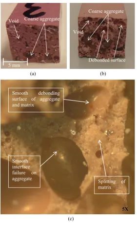
Figure 8. Typical failure surface of tensile specimens of; (a) U-EG3, (b) C-EG3, (c) magnified interface of C-EG3.
Figure 8 shows the typical failure pattern of the tensile specimens. All the unconditioned grouts fail due to splitting, which are perpendicular to the length. The formation of crack in the grouts is sudden and a splitting sound is heard. An observation that can be made is that voids are present in all three cured grouts. The failure surface of grout EG1 has a smooth appearance in both test conditions. The failure surface of unconditioned specimens exhibit smooth texture. Failure surface of the grout U-EG3 is shown in Figure 8(a), which is also representative of U-EG2. It can be seen from the cracked surfaces of the U-EG3 grout that the failure occurs in the matrix through the aggregates. On the other hand, failures in the C-EG3 grout progress slowly compared to grout C-EG1 and are not perfectly perpendicular to the length or straight along the thickness. The failure surfaces of the grout C-EG3 specimens are similar; they appear jagged and the coarse aggregate fillers are visible as shown in Figure 8(b). The magnified view of the failure surface of the conditioned C-EG3 as given
(a)
(c)
5X
Smooth debonding surface of aggregate and matrix
Splitting of matrix
Smooth interface failure on aggregate
(b)
Coarse aggregate
Debonded surface Void
Coarse aggregate Void
AIMS Materials Science Volume 3, Issue 3, 832-850.
in Figure 8(c) shows that failure occurred in the matrix-aggregate interface unlike the phenomenon in the unconditioned specimens. The interface failure between the resin matrix and the aggregate is due to the effect of hygrothermal conditioning which weaken the interfacial bonding.
3.3.3. Flexural behaviour
[image:13.595.116.476.364.567.2]Figure 9 shows a comparison of typical the load-deflection behaviour of the grout specimens in flexure. The unconditioned grouts show linear load-deflection behaviour prior to failure. Grout EG1 has the highest flexural strength with a value of 53 MPa. Grout U-EG3 has strength of 35 MPa which is lower than grout U-EG1 due to the addition of coarse filler. The flexural stiffness of grouts U-EG2 and U-EG3 is about 13 GPa which is higher than that of grout U-EG1. Conditioned grouts C-EG2 and C-EG3 also showed linear load-deflection behaviour prior to failure, whereas grout C-EG1 exhibits a brief plateau before failure. Grout C-EG2 exhibits the highest load and least deflection prior to failure while grout C-EG1 exhibits the lowest load and highest deflection. As shown in Table 3, despite the intermediate tensile strength and elastic modulus, grout C-EG2 has the highest flexural strength and flexural stiffness, at 19 MPa and 0.53 GPa, respectively. Grout C-EG1, which shows the highest tensile strength and elastic modulus, exhibits the lowest flexural strength and flexural stiffness. This suggests that flexural stiffness of the grouts are considerably affected by hygrothermal ageing.
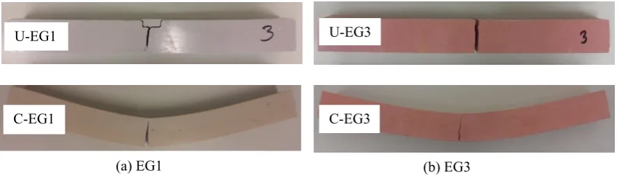
Figure 9. Typical flexural stress-strain behaviour of the grouts.
and aggregate. This behaviour is comparable to the tensile failure behaviour of the conditioned specimens.
Figure 10. Typical failure pattern of flexural specimens. 3.3.4. Shear behaviour
The shear strength of the unconditioned grouts U-EG1, U-EG2 and U-EG3 are 30, 25 and 28 MPa, respectively while the conditioned grouts C-EG1, C-EG2 and C-EG3 are 10 MPa, 3 MPa and 6 MPa, respectively. Hence, the shear strength is affected adversely due to inclusion of filler. Grout C-EG3 exhibits lower shear strength than that of grout C-EG1. Figure 11 shows the relative comparison of load and crosshead displacement of the grouts under shear loading. Grouts EG1, EG2 and U-EG3 exhibit linear load-displacement behaviour before distinct reduction in load during failure, which is also applicable for C-EG1. However, grouts C-EG2 and C-EG3 show relatively smooth transition in the load-displacement plot during failure.
The failure occurs suddenly after the peak load with no prior warning in all the unconditioned grouts. However, the conditioned specimens undergo considerable deformation prior to failure. The failure is made up of two diagonal cracks and a failure wedge in-between the cracks in the unconditioned grouts as shown in Figure 12. Typically, formation of a shear wedge is observed from one crack running from bottom of the top notch towards the bottom plane surface and the second crack running almost parallel from the top of the bottom notch diagonally towards the top plane surface. Hence, it is evident that the failure in the unconditioned grouts is a combination of shear and tension which was also reported in Iosipescu coupon specimen made of graphite [18]. On the other hand, the conditioned grouts failed gradually after the peak load. The angle of the shear cracks was between 30 and 45º. The failure of the conditioned grout C-EG1 is composed of two diagonal cracks and a failure wedge in-between the cracks is similar to U-EG1. Whereas, the grouts EG2 and C-EG3 exhibit one large crack with smaller parallel cracks near the notches at the specimen edges.
U-EG1
C-EG1
U-EG3
C-EG3
AIMS Materials Science Volume 3, Issue 3, 832-850. Figure 11. Typical shear load-deflection behaviour.
Figure 12. Typical failure pattern of shear specimens.
4. Discussion
4.1. Evaluation of the grouts
Mendis [7] suggested that, grouts having compressive and tensile strength ranges of 83–97 MPa and 28–48 MPa, respectively have the potential to be used in structural rehabilitation. An epoxy-grouted technology for pipeline repair was described by Vu et al. [19] where the compressive, and tensile strengths specified in that article were 75 and 23 MPa, respectively. Mattos et al. [20] investigated with an alternative repair system, where the lowest compressive strength of the infill materials was 56 MPa. Sing et al. [21] found compressive and tensile strength range 60–88 MPa, and 19–33MPa, respectively. Thus, all the investigated grouts can be used for structural repair. The conditioned grouts EG1 and EG3 have the potential to be used on the similar type of repairs in terms of the compressive performance. Detailed numerical study of grouted sleeve repair using an epoxy grout with modulus of 4 GPa for repairing steel pipe with metal loss suggested that an overall stiffer grout is necessary, especially when grouts are subjected to shrinkage during curing, to minimise the pipe strains [22]. The fact, that there is considerable reduction in the stiffness due to conditioning, suggests that the investigated grouts may not be suitable for pipeline repair at an elevated service
(a) EG1 (b) EG3
U-EG1 U-EG3
[image:15.595.72.526.304.471.2]temperature of 70 oC. However, According to ISO/TS 24817, the grouts may be suitable at their
conditioned state for Class 1 repair for low pressure applications, which has a lower design temperature range (less than 40 oC). Moreover, it should be kept in mind that investigation of the
conditioning at relevant temperature specified by standard is also necessary to come to such conclusion, even for Class 1 repair. Besides, it is to be noted that a higher conditioning temperature is adopted for this study considering glass transition temperature Tt as the ceiling instead of Tg.
Hence, the applicability of these grouts in a grouted sleeve repair system is subjected to further investigation on a case-by-case basis.
4.2. Effect on mechanical properties
[image:16.595.76.518.479.628.2]Table 4 provides a summary of the percentage reduction of mechanical properties of the hot-wet conditioned grouts compared to the properties of the similar grouts cured at 23°C for 7 days and tested at room temperature. The comparison suggests considerable reduction of properties among the hot-wet conditioned grouts. The fact that epoxy resins based composites can go through considerable deterioration under hygrothermal conditioning was also reported recently [23,24,25]. The dominant reduction occurs in the stiffness of the grouts. Tensile and flexural moduli of the hot-wet conditioned grout decrease by more than 90% compared to unconditioned grouts. The tensile strength of the grouts EG2 and EG3 are also reduced by more than 90%. As general practice, a minimum temperature of 12 oC for placing and maximum temperature of 82 oC for service condition was suggested for epoxy grouts intended for structural applications, where a higher temperature can lead to higher stiffness and cracking [26]. It is to be noted that this guideline is applicable for elevated temperature only. Studies of silica filled epoxy resin under hot-wet conditioning confirmed that there were reduction in the strength and elastic modulus due to the hydrolysis occurring after the debonding of the filler-matrix interface caused by the absorbed water [22,27].
Table 4. Summary of reduction of the mechanical properties.
Properties
% Reduction compared to unconditioned specimens cured for 7 days at 23oC
EG1 EG2 EG3
Compressive Compressive strength 12.3 71.4 62.2
Compressive modulus 92.5 91.9 94.9
Tensile Tensile strength 61.8 92.2 93.3
Tensile modulus 92.2 98.9 99.8
Flexural Flexural strength 83.6 43.8 63.4
Flexural modulus 98.0 95.9 98.4
Shear Shear strength 65.8 86.7 77.7
The reduction in compressive strength is higher in the coarse aggregate filled grouts (EG2 and EG3) than that of the fine filled grout EG1. Hence, coarse filled system is more susceptible to degradation under hygrothermal conditioning. Grouts EG2 and EG3 show relatively prolonged ductile deformation under tensile load compared to grout EG1. It is evident that the inclusion of coarse filler has contributed to the reduction of the tensile strength as well as stiffness when tested at elevated temperature conditions.
AIMS Materials Science Volume 3, Issue 3, 832-850.
and matrix in the conditioned grouts is smooth indicating that interface bonding between aggregate and matrix is weaker than the particle strength of the aggregate. Again, since the matrix itself splits, the resin matrix is weaker than the aggregate particle strength. This behaviour in the conditioned grouts is opposite to the behaviour in unconditioned grouts. Both of these scenario are described in another study [28]. The failure in the unconditioned grouts is such that the individual aggregate strength is higher than both the resin matrix and the interface bond. The possibility is that the aggregate is strong enough to provide sufficient resistance against failure where the failure occurs thorough the resin matrix and the aggregate, provided the matrix is also stronger than the interfacial bonding energy. In contrast, this situation of conditioned grouts especially grouts with coarse filler align with the argument that the resin matrix, and the matrix-interface bond is weaker than the individual aggregate. From a detailed magnified view of grout EG3 shown in Figure 8(c), it can be seen that aggregates does not split due to tensile force. This implies that hot-wet conditioning reduced the strength of the matrix-grout interface of the grouts.
The flexural properties of the unconditioned grout EG1 are found to be higher than that of grout EG2 and EG3. However, the flexural properties of grout EG1 are found to be lower than that of other grouts, whereas tensile properties of grout EG1 are found higher as shown in Table 3. This is due to the fact that conditioned grout specimens soften due to the action of elevated temperature. Hence, tensile crack form at the bottom of the specimens when loaded. Since the crack is formed at the bottom, the top of the specimen goes through compression. Grout EG1 has the highest resin/filler ratio than that of other grouts and provides lower resistance due to softening of the resin in the matrix. Besides, coarse filler is no longer acts as a reinforcement against crack in the conditioned grouts.
4.3. Effect on thermal properties
The tan δ peak, Tt of the conditioned grouts is found to be about 60–70 ºC, which is about 20 oC
lower than the unconditioned grouts. Again storage modulus, Tg is also reduced by about 20 oC when
conditioned. This implies that hot-wet conditioning reduced the glass transition temperature of the grouts. Elevated temperature in conjunction with moisture were found to reduce the glass transition temperature by a range of 9–25 oC, hereby the service temperature in an intensive study on a number
of epoxy grouts for structural application [29]. Hence, the mechanical properties are affected by the hot submerged condition (70 ºC) and elevated temperature, which is above their glass transition temperature as determined by storage modulus. It is evident that the appropriate glass transition assignment approach used here, taking the peak of the Tan δ curve (Tt), is less conservative approach
than taking the onset of decline in the storage modulus (Tg). Furthermore, Tg and Tt are found to
reduce by approximately 20 ºC after hot-wet conditioning, which for instance justifies the 20–30 °C temperature buffer used for Type A and Type B pipeline repairs, based on the guidelines presented in ISO/TS 24817. Hence, further investigation on the properties is suggested considering the Tg instead
of Tt of the unconditioned specimen as benchmark.
5. Conclusion
Three epoxy-based grouts were tested for mechanical and thermal properties at 23 oC. The grouts were also hot-wet conditioned for 1000 hours at 70 oC and tested at 65 °C to observe the
The average moisture absorption is observed for the grouts within a range of about 0.5–2.7% after 1000 hours, when two of the three grouts achieved saturation, indicating that extended conditioning beyond 1000 hours may be necessary to achieve saturation for specific grout of interest.
The compressive strength and modulus of the investigated grouts range from 100–120 MPa, and 5.6–11.0 GPa, respectively indicating their suitability for structural rehabilitation of offshore pipelines.
The coarse aggregate is found to be effectively contributing against crack in the unconditioned grouts. However, there is reduction of bonding on the aggregate-matrix interface after conditioning, which causes reduction of tensile strength and modulus.
The grouts have experienced reduction in mechanical properties due to elevated temperature moist curing limiting their applicability in a submerged service condition at the elevated temperature of 70 oC, which is close to their glass transition temperature.
The glass transition temperatures, Tg and Tt of the grouts are found to be within a range of 50–
60 °C, and 80–90 °C, which are reduced by about 20°C after conditioning, which confirms that glass transition temperature defines a significant margin for maximum temperature beyond which polymer undergoes considerable reduction in properties under submerged condition.
Acknowledgement
This work was undertaken within P1.3 Deep Water Composites, part of the Cooperative Research Centre for Advanced Composite Structures (CRC-ACS) program, established and supported under the Australian Government’s Cooperative Research Centres Program.
Conflict of Interest
The authors report no conflict of interests in this research.
References
1. International Energy Agency (2014) World Energy Outlook, Paris.
2. Spiegel A, Bresch D (2013) Building a sustainable energy future: risks and opportunities, Zurich. 3. Shamsuddoha M, Islam MM, Aravinthan T, et al. (2013) Effectiveness of using fibre-reinforced
polymer composites for underwater steel pipeline repairs. Compos Struct 100: 40–54.
4. Lim K, Azraai S, Noor N, et al. (2015) An Overview of Corroded Pipe Repair Techniques Using Composite Materials. Int J Chem Mol Nucl Mat Metall Eng 10: 19–25.
5. Palmer-Jones R, Paterson G, Nespeca GA (2011) The flexible grouted clamp-a novel approach to emergency pipeline repair. In: Rio Pipeline Conference & Exposition; Rio de Janeiro, Brazil. 6. Azraai S, Lim K, Yahaya N, et al. (2015) Infill materials of epoxy grout for pipeline
rehabilitation and repair. Malaysian J Civil Eng 27: 162–167.
7. Mendis P (1985) Commercial applications and property requirements for epoxies in construction. ACI Special Publication SP: 127–140.
8. Prolongo SG, del Rosario G, Ureña A (2006) Comparative study on the adhesive properties of different epoxy resins. Int J Adhes Adhes 26: 125–132.
9. Kneuer RL, Meyers M (1991) Strengths and limitations of epoxy grouts. Concrete International March: 54–56.
AIMS Materials Science Volume 3, Issue 3, 832-850.
11. Sum WS, Leong KH, Djukic LP, et al. (2016) Design, testing and field deployment of a composite clamp for pipeline repairs. Plast Rubber Compos 45: 81–94.
12. Djukic LP, Leong AYL, Falzon PJ, et al. (2014) Qualification of a composite system for pipeline repairs under dry, wet, and water-submerged conditions. Journal of Reinforced Plastics and Composites 33: 566–578.
13. ISO/TS 24817 (2006) Petroleum, petrochemical and natural gas industries - composite repairs of pipework - qualification and design, installation, testing and inspection. London: International Organization for Standardization.
14. Shamsuddoha M, Islam MM, Aravinthan T, et al. (2014) Compressive, tensile and thermal properties of epoxy grouts subjected to underwater conditioning at elevated temperature. In: 23rd Australasian Conference on the Mechanics of Structures and Materials (ACMSM23); Byron Bay, Australia. 15. Soles CL, Chang FT, Gidley DW, et al. (2000) Contributions of the nanovoid structure to the
kinetics of moisture transport in epoxy resins. J Polym Sci Part B: Polym Phys 38: 776–791. 16. Goertzen WK, Kessler MR (2007) Dynamic mechanical analysis of carbon/epoxy composites.
Comp Part B 38: 1–9.
17. Yang Y, Xian G, Li H, et al. (2015) Thermal aging of an anhydride-cured epoxy resin. Polym Degrad Stab 118: 111–119.
18. Manhani LGB, Pardini LC, Levy NF (2007) Assessement of tensile strength of graphites by the Iosipescu coupon test. Mater Res 10: 233–239.
19. Vu D, Glennie A, Booth P (2011) Pipeline repairs and hot tapping technologies using epoxy based grouted technology. In: 6th International Offshore Pipeline Forum (IOPF 2011); Houston, Texas, USA.
20. Mattos HSdC, Reis JML, Sampaio RF, et al. (2009) An alternative methodology to repair localized corrosion damage in metallic pipelines with epoxy resins. Mater Des 30: 3581–3591. 21. Sing LK, Azraai SNA, Yahaya N, et al. (2015) Comparison of Mechanical Properties of Epoxy
Grouts for Pipeline Repair. Res J App Sci Eng Technol 11: 1430–1434.
22. Wang L, Wang K, Chen L, et al. (2006) Hydrothermal effects on the thermomechanical properties of high performance epoxy/clay nanocomposites. Polym Eng Sci 46: 215–221.
23. Liu S, Cheng X, Zhang Q, et al. (2016) An investigation of hygrothermal effects on adhesive materials and double lap shear joints of CFRP composite laminates. Compos Part B Eng 91: 431–440. 24. Almeida JHS, Souza SDB, Botelho EC, et al. (2016) Carbon fiber-reinforced epoxy
filament-wound composite laminates exposed to hygrothermal conditioning. J Mat Sci 51: 4697–4708. 25. Osman E, Rashid MWA, Edeerozey M, et al. (2016) Hygrothermal effect on mechanical and
thermal properties of filament wound hybrid composite. J Adv Manuf Technol 1–12.
26. Harrison DM (2000) The Grouting Handbook: A step-by-step guide to heavy equipment grouting. Houston, Texas: Gulf Publishing Company.
27. Brun E, Rain P, Teissedre G, et al. (2007) Hygrothermal aging of a filled epoxy resin. In: IEEE International Conference on Solid Dielectrics; Winchester, United Kingdom.
28. Suwanprateeb J (2000) Calcium carbonate filled polyethylene: correlation of hardness and yield stress. Compos Part A 31: 353–359.
29. Blackburn BP, Tatar J, Douglas EP, et al. (2015) Effects of hygrothermal conditioning on epoxy adhesives used in FRP composites. Constr Build Mater 96: 679–689.