Dissertation submitted to
THE TAMILNADU Dr. M. G. R. MEDICAL UNIVERSITY
In partial fulfillment for the Degree of
MASTER OF DENTAL SURGERY
BRANCH III
ORAL AND MAXILLOFACIAL SURGERY
which forms the foundation of my life and all my work.
With deep satisfaction and immense pleasure, I present this work undertaken as a Post Graduate student specializing in Oral & Maxillofacial
Surgery at Ragas Dental College and Hospital. I would like to acknowledge my working on this dissertation which has been a wonderful and enriching learning
experience.
I am greatly indebted to Dr. M.Veerabahu, My professor and Head of the Department, Oral and Maxillofacial surgery, Ragas Dental College and Hospital,
Chennai, for his guidance and support. His constant guidance in the academic front as well as in surgical aspect during my studies has helped me a lot. I have
been fortunate to study under his guidance and support. These memories definitely would cherish throughout my life.
I would like to extend my heartfelt gratitude to Professor Dr.S.Ramachandran, Principal, Ragas Dental College and Hospital, for allowing
I express my personal thanks to madam for being so tolerant, encouraging and understanding. I shall forever remain indebted to her for her valuable
guidance and input throughout the making of this dissertation without which I would have never accomplished this particular research. It was an enriching
experience to have spent three years of my life under her guidance.
I would also thank my Professor Dr.B.Vikraman, for sharing his unparalleled academic & clinical knowledge and constant encouragement during
my post graduation. He has always ignited the spark in me and the extra shine which has come in my work is all due to his guidance. He has been instrumental in introducing the Mimics software to our department, using which a lot of
creative work is being done in the field of CT data simulation and virtual surgical planning. I will always be benefitted from the distinctive quality imparted in us to
look into problems from all three dimension.
I owe enormous debt of gratitude to my Professor Dr.J.A.Nathan, for his precious advices, generous support and plentiful knowledge he has shared.I also
I sincerely thank my teachers Dr.Venkat and Dr.Shankar for their valuable guidance, encouragement and help during my post graduation period.
I would also extend my gratitude to Dr.Muthumani, Dr. Vinesh, Dr. Prabhu and Dr.Karthik for their valuable suggestions and support.
I sincerely thank my colleagues Dr.Kiran, Dr.Prashanthi , Dr.Prashant, Dr.Saileesh and Dr.Sunil for their constant support, constructive criticism at every step and selfless co-operation during my course. I would also like to thank
my seniors Dr.Rajarshi and Dr.Akash for their encouragement and for having done their bit to help me during the study.
I would also like to extend my sincere gratitude to the paramedical and non-teaching staff of the institution for their support and help.
I wish to thank Mr.Rupesh Kumar C, Project Engineer from Ramaya
School of Advanced Studies, Bangalore for doing the analysis in this study.
I would like to thank my Parents for all the sacrifices they have made to
I have no words to express my gratitude towards my grandmother whose
blessings are always there with me.
I would like to dedicate this dissertation to my late Grandfather Mr.Krishan Lal Vasudeva, who always wanted me to reach great heights in my
S .No. TITLE PAGE NO.
1. INTRODUCTION 1
2. AIM AND OBJECTIVES 7
3. REVIEW OF LITERATURE 8
4. MATERIALS & METHODS 32
5. RESULTS 48
6. DISCUSSION 50
7. SUMMARY & CONCLUSION 73
1
INTRODUCTION
Mandibular fractures constitute a frequent injury treated in
craniomaxillofacial surgery, mainly caused by road traffic accidents, interpersonal violence and falls.2 The angle is one of the most frequent sites for fractures of the lower jaw, accounting for between 20% and 36% of all
mandibular fractures. 29 The presence of impacted third molar tooth which diminishes bone quality and stability plus the thinner cross section area of this
region of the mandible (Tevepaugh and Dodson, 1995) contributes to the frequency of this site of fracture.
Angle fractures are considered the most critical of all mandibular
fractures. This is because they generate the highest frequency of complications relative to other mandibular fractures, ranging from 0 to 32 % 4, particularly in relation to insufficient stability of fracture fixation.
The biomechanics of angle makes treatment of fractures in this region more difficult, the traditional treatment method (compression & reconstruction
plates) has the highest complication rate (17%) in some populations which include abscess formation, osteomyelitis, malunion, nonunion and malocclusion.
2
the line of fracture. The ideal method of treatment of mandibular fracture should have the objectives of perfect anatomical reduction, complete and stable fixation
and painless mobilization of the injured region around its fixation.
Methods for open reduction of mandibular fractures have changed and
diversified enormously in recent decades, but there is still controversy regarding the optimal treatment.4
Thus the great variety of osteosynthesis methods in use indicates that so
far no general agreement has been reached on mandibular fractures (Ellis and Ghali,1991; Ellis,1999).
Rigid internal fixation has been found to be an effective modality in the treatment of facial fractures for the past 3 decades. In the present scenario open reduction & rigid internal fixation can be achieved with a variety of different
plating systems, some using an intraoral approach and some an extraoral approach.
The development of these systems for treatment of mandibular fractures has meant a change in criteria for post-surgical immobilization with a more rapid return of function, resulting in patients to resume normal function earlier.
3
The majority of simple, nondisplaced or minimally displaced fractures of the symphysis, parasymphysis and mandibular body can be adequately treated
by osteosynthesis with 1 or 2 miniplates. Fixation of more complex fractures like comminuted fractures and fractures of the mandibular angle is much more
controversial.
Philosophy of compression plating and the method of miniplate osteosynthesis compete with each other. Use of miniplate osteosynthesis allows
early mobilization and has the advantage of being easy to bend and adapt and also found to be cost effective. Though fixation of such plates has been shown to
simplify the surgery and reduce the surgical morbidity, it failed to surpass the predictability of rigid fixation. However, questions concerning the stability provided by miniplate fixation of mandibular angle fracture have become a point
of contention among surgeons, based on recent clinical and experimental studies some authors described inferior border distraction caused by application of
loading forces close to the fracture line.
Some authors found an unacceptably high rate of complications (28%) using two miniplates and others reported no differences in outcome when a
single plate was compared with two plates.
These shortcomings have led to the development of three - dimensional
4
miniplate (3-D miniplate) would provide both a functional level of stability requisite of fixation with minimum operative time and relatively low
complication rate.
It consists of two 4- hole miniplates joined by three or four
interconnecting cross struts. In combination with the screws monocortically fixed to the outer corticalis, the rectangular plate forms a cuboid which provides three dimensional stability.29 The plates are adapted to the bone according to champy‟s principles.33
The geometry of 3-D strut plate conceptually allows for an increased
number of screws, stability in three- dimension and resistance against torque forces while maintaining a low profile and malleability.
Finite element analysis (FEA) is a commonly employed experimental
research technique which enables us to study the effects of geometrical and material variations under load and internal mechanical process.70 Originally used in structural analysis, it has now revolutionized dental biomedical research.
It allows modeling of structures or systems that approximates reality.
A „system‟ which is assessed in FEA is usually made up of a continuous
5
supported, and loaded at its vertex and other specified location on edges or inside, called “nodes”.75
Each node can have a number of independent action (force or moment) or displacement (deflection or rotation) components called “Degrees Of
Freedom” (DOF) along a certain direction.
FE method requires a huge amount of computation, so its application is supported by advanced computer technology. ANSYS and ABAQUS are two
well – known FE softwares used for analysis. ANSYS has three fundamental modules. They are Preprocessor, Solution and General Postprocessor modules.
Pre processor - The creation of a FE model is done by preprocessor module. It
includes: Step 1: Selection of the type of element
Step 2: Assigning material properties to the model - Elastic modulus and Poisson‟s ratio
Step 3: Creation of model geometry – 2D or 3D
Step 4: Mesh generation- division of the model into small and finite elements
Step 5: Application of structural loads and constraints to the model
Solution - Solving of the model using the solution module.
Post processor – Results of the analysis can be accessed using the general post
6
Thus when factors like clamping conditions and loading stress are known, the deformations and tensions of these elements (Bathe, 1990)can be
calculated at each node. Due to their mutual interlinking (the same displacement and rotation of the nodes in all dimensions of space), the same applies to the
deformation of overall structure. In turn derived parameters (stresses, expansions etc) can be calculated from this and consequently predictions can be made of possible failure.
Mechanical analysis using a finite element analysis have demonstrated that stability at the fracture interface differs with different plating strategies in
both angle fracture models and condyle fracture models. 41
The aim of this study is to evaluate and describe our clinical experience with the use of 3 – dimensional plating system in mandibular angle fracture
fixation.
It also focuses on the biomechanical behavior of fractured mandible
7
AIM AND OBJECTIVES
To evaluate the treatment results of open reduction and internal fixation using 3 Dimensional miniplate for fixation of mandibular angle fracture in
regard to:
Surgical outcome
8
REVIEW OF LITERATURE
The recording of incidence of mandibular fractures appeared as early
as 1650 B.C, when Egyptian, Smith Papyrus described the examination, diagnosis and treatment of mandibular fractures and other surgical ailments.
Around 450 B.C, Hippocrates the “father of medicine” was the first
to describe the basic principles of modern fracture repair, reduction and stabilization. He described direct re -approximation of the fracture segments
with the use of circumdental gold wires. He also advocated wiring of adjacent fragment with external bandaging to immobilize the fracture.
Salerno (1180) described the importance of establishing occlusion in
the management of mandibular fracture.
Gugleilmosalicetti (1492) introduced the theory of maxillomandibular fixation by stating that “tie the teeth of the uninjured jaw to the teeth of the injured jaw”.
Hansmann (1886)38 was the first to develop and present a procedure
for subcutaneous fixation of bone fragments with a plate screw-system. He is, therefore, the inventor of plate osteosynthesis.
9
aluminium, brass, copperand silver. The first screws were conical and had flattenedround heads with a simple screwdriver slot. Latermodels were
cylindrical with machine cut threads andhad self-drilling tips.
Collins (1920) and Eggers and Roosth (1959)38 developed plates which possessed long and slotlike holes. With thisso-called internal contact
splint the fracture ends could be approximated after the screws had been
inserted. This modification later became the „„compression plate‟‟.
Danis (1949)38 presented the first compression plate for osteosynthesis. His work„„The´orie et pratique de l‟osteosynthe`se‟‟ leads to a change in
osteosynthesis to introduce primary stability.
Luhr (1968)38 introduced „„compression osteosynthesis‟‟ of the mandible. By usinga vitallium plate containing eccentric holes and selfcutting
screws with a conical head, he created axial compression.
Spiessel (1969)38 modified the “dynamic compression plates” used for
limb surgery to match the dimensions of the mandible and applied them clinically. These plates were fixed at the buccal lower border of the mandible using bicortical screws. In addition, tension banding was secured by either a
10
Miniplates osteosynthesis
Brons and Boering (1970)38 inserted small finger plates for
mandibular fractures which were originally used in hand surgery. They placed the plates at the lower border of mandible which was biomechanically
unfavourable.
Thus with miniplates the path of static compression was switched to
that of dynamic compression.
Michelet et al (1973)38 applied vitallium miniplates in more than 300 mandibular fractures. He placed them along the tensile trajectories and
insetedmonocortical screws to avoid injury to tooth roots. Post operatively mandibulo – maxillary immobilization was not necessary in most cases.
Champy et al (1975)38 modified this method to make it clinically more
applicable. He developed an ideal line for osteosynthesis in ithe mandible - a line of maximum tensile stress running from the oblique line along the base of
the alveolar ridge to the mental foramen. Here a single miniplates is sufficient. Additional torque required a 2nd more basal plate.
Prein et al (1976)38 developed the so called “reconstruction plates” or the “load bearing plates” which allowed none or only minor movement
between plate and bone fragments. They were used to bridge the gaps of
11
Edward Ellis (1993)20 evaluated a sample of 52 patients with fracture of the mandibular angle treated with AO reconstruction plate. The plate was
three dimensionally bendable. The three screws on each side of fracture with this plate provided neutralization of functional forces in the absence of
compression. Use of this plate for mandibular angle fracture was found to be very predictable and was associated with low rate of complications.
Mostafa Farmand (1995)21 developed a new titanium plating system -
the 3D plating system. A total of126 patients with trauma, craniofacial, orthognathic and reconstructive surgery were treated. 245 three dimensional
plates of different size and shape were inserted. 43plates were used on cranium, 112 plates in the midface and 90 plates on the mandible. No patient had intermaxillary fixation. At the time of plate removal after 9 months, all the
plates and screws were seen incorporated nicely into the bone. There were only 3 infections. Thus the complication rate related to the plates was low.
Vivek Shetty et al (1995)39 conducted an invitro study to determine
and compare the initial mechanical stability and functional capability of six contemporary internal fixation systems used to fix mandibular angle fractures.
The fixation system comprised of the compressive system and the adaptive systems. Compressive systems included the 1) eccentric dynamic compression
12
significantly. Even at low masticatory loads the adaptive systems had instability which was 2 to 3 times less than that of compressive systems. With
this it was concluded that compressive fixation systems were biomechanically superior to adaptive systems and provide good immediate functional stability
to reduced mandibular angle fractures.
Edward Ellis III (1996)17 evaluated the use of a single noncompression miniplate for stabilization of fractures of the mandibular
angle in 81 patients. The plate was fixed with 2.0 mm self threading screws placed through a transoral incision. 13 patients (16%) experienced
complications requiring surgical intervention. Most of the complications (n =1l) were minor and could be treated in the office. Most commonly,
intraoral incision and drainage and later removal of the bone plate were
required. All patients with minor complications had clinical union. Only two complications required hospitalization for intravenous antibiotics and further
surgery. Hence it was concluded that the use of a single miniplate for fractures of the angle of the mandible is a simple, reliable technique with a relatively
small number of major complications.
Richard Haug et al (1996)36 compared the conventional technique of
mandibular angle fracture plating with two biomechanically dissimilar
13
little bearing on clinical fracture fixation but that the monocortical screws
appear to be a weak link in the system.
J .M.Wittenburg et al (1997)27 performed a biomechanical study investigating the effectiveness of fixation devices of simulated angle fractures in sheep mandibles. The fractures were stabilized by a Leibinger 8 – hole 3-D
plate, Synthes 8- hole mesh plate Synthes 6 hole reconstruction plate. Each mandible was tested in bending class III cantilever model. The 3- D plate
showed plate deformation in bending > 230 N. The gap and displacement values for the mesh and 3-D plate were comparable to those of the
reconstruction plate. These results indicate that a 3-D or mesh plate can be used for fixtion of mandibular angle fractures.
J.Tams et al (1997)28 conducted a study to determine and compare
bending and torsion moments across mandibular fractures for different positions of the bite point and different sites of the fracture. It was found that angle, body and symphysis fracture, each have a characteristic load pattern.
These load patterns should play a decisive role in the treatment of mandibular fractures with regard to number and positioning of plates.
To formulate criteria for number and positioning, as well as mechanical properties and design of the plate systems, the load across the
14
neutralize positive bending moments that results in tension in the alveolar region and compression at the lower border,the bone plate should be positioned as “ high” as possible, i.e. in the alveolar region. But if two plates
are used then, the upper plate should be positioned high while the other is
placed on the lower border. The upper plate has to carry the largest loads and hence should be the larger one.
Jasser Ma’aita et al (2000)25 evaluated the association of mandibular
angle fractures with the presence and state of eruption of the mandibular third molar.A retrospective study was conducted by utilizing records and
radiographs of 615 patients as data source. Angulation of third molar was measured by using method of Shillen in which angles were classified as vertical +/ - 10, mesioangular and distoangular +/ - 11 to 70, and horizontal
more than+/ - 71. The results showed that the mandibular angle that contains an impacted third molar is more susceptible to fracture when exposed to an
impact than an angle without third molar.
K.L.Gerlach et al (2002)30 evaluated maximal biting forces in 22 patients with mandibular angle fractures treated with miniplates osteosynthesis
according to Champy. An electric test procedure for evaluating the load resistance between the incisors, canines and molars was carried out 1 to 6
15
of the maximal vertical loading found in controls was registered. These values
increased to 58% at the 6 th week postoperatively.
Guimond et al (2005)12 evaluated the complication rate with the use of 2.0- mm 3 – dimensional curved angle strut plate for mandibular angle fracture fixation. A retrospective evaluation of 37 patients with
noncomminuted mandibular angle fractures fixated with a transorally placed 2.0- mm 3 – dimensional curved angle strut plate was done. The results
revealed that only two patients developed infections requiring plate removal and reapplication of fixation. Both the patients had a molar in the fracture line
that was left in place during 1st operation. One patient developed a mucosal wound dehiscence without consequence. All the patients who developed a sensory deficit as a result of surgery reported full recovery of sensation. Thus
the study suggested that the multidimensional strut plate carries low morbidity and infection rates that may prove to be comparable to the “gold standard”
reconstruction plate.
Babu S. Parmar et al (2007)10 evaluated the efficacy of 3-D stainless steel miniplates in the treatment of mandibular fracture. Seven patients were
16
dimensional stability with low morbidity and infection rates. The only probable limitation of these plates is excessive implant material due to extra
vertical bars.
Juergen Zix et al (2007)29 evaluated the clinical usefulness of 3- Dimensional (3D) miniplate for open reduction and monocortical fixation
of mandibular angle fractures. In 20 consecutive patients, noncomminuted mandibular angle fractures were treated with open reduction and fixation using
a 2 mm 3D miniplate system in a transoral approach. Postoperatively none of the patient developed infection (0%). But two patients with normal
preoperative sensation developed sensory deficit after surgery which regained normal sensation after 3 months. The most important complication observed in this study was the fracture of the straight 3-D plate. This was attributed to
several factorslike multiple bending, improper placement of plates, insufficient fracture reduction or overdrilling of the screw holes which have negative
effect on the stability of fixation resulting in plate fracture. It was thus suggested that 3D plating system is a suitable method for fixation of simple mandibular angle fractures. It is an easy-to-use alternative to conventional
miniplates, However, its application should be limited to cases where the fracture site has sufficient interfragmentary stability. The curved 3D plate can
17
A Siddiqui et al (2007)6 compared the use of one miniplate (n = 36) with that of two miniplates (n = 26) for the treatment of mandibular angle
fracture in a randomised trial. 36 patients had one / more complications i.e. 22 patients (61%) with a single plate and 14 patients (54%) with two plates. It
was thus concluded that two miniplates are no more effective than one in the treatment of angle fractures.
Aleysson o paza et al (2008)2 conducted a retrospective study where
115 mandibular angle fractures were reviewed. It was concluded that angle fracture management outcomes are affected by many factors beyond method
of fixation. These include thinner cross sectional area than that of the tooth bearing region and biomechanical forces acting on the mandible (including the
position of the masticatory muscles).
Rudolf Seeman et al (2010)37 assessed the complication rates of mandibular angle fractures treated by open reduction. The 10 year retrospective study included 322 patients with 355 surgically treated
mandibular angle fractures. The data showed that successful treatment occurred in 93.69% of fractures with 1open reduction and in 6.31% with 2
open reductions. Of surgically treated patients 71.47% (238) were completely free of complications. No significant differences were found between
18
Manoj kumar jain et al (2010)33 compared the 3- D imensional and standard (Champy‟s) miniplate fixation in the management of mandibular
fractures. A prospective randomized clinical trial was carried out for a period of 1 year. Patients were divided into 2 groups by lottery method. Fixation was
done using either 3 D 2 mm stainless steel plates (group I) or standard miniplate (group 2) using Champy‟s principle of osteosynthesis . Patients were followed for 2 months for wound dehiscence, infection, mobility,
postoperative occlusion and radiological evaluation of reduction and fixation. In group I, 2 patients had mild segmental mobility, 2 patients had surgical site
infection and 2 patients involving mental nerve had involved roots of teeth (P =.07). Radiological evaluation showed a significant difference in fixation
between the 2 groups, especially in cases involving mental nerve and oblique fractures. Thus they concluded that Champy‟s miniplates system is a better
and easier method than the 3 D miniplates system for mandibular fracture
fixation. It is difficult to adapt and is unfavourable to use in cases of oblique fractures and those involving mental nerve.
Eduardo Hochuli -Vieira et al (2011)14 evaluated the clinical
outcome of 45 patients with mandibular angle fractures treated by intraoral access and a rectangular grid miniplate with 4 holes and stabilized with
19
changes that were resolved with small occlusal adjustments. Before surgery, 15 patients (33.33%) presented with hypoesthesia of the inferior alveolar
nerve; 4 (8.88%) had this change until thelast clinical control, at 6 months. It was concluded that the rectangular grid miniplate was stable for the treatment
of simple mandibular angle fractures through intraoral access, with low complication rates, easy handling, and easy adjustment, with a low cost. Concomitant mandibular fracture may increase the rate of complications. This
plate should be indicated in fractures with sufficient interfragmentary contact.
FINITE ELEMENT ANALYSIS
Clough RW (1960)47at the 2nd conference on electronic computation of the American society of civil engineers presented a paper in which he coined the term “FINITE ELEMENT” and applied it on his paper “Finite Element Method in plain stress analysis”.
Farah JW, Craig RC (1974)54worked and produced an article “Finite
element analysis on a restored asymmetric 1st molar”. He created history by bringing finite element method (FEM) study in dentistry for the first time, proving its efficiency to be better than photo elastic study in terms of easy
20
Weinstein AM et al (1976)86 was the first to use Finite element analysis in implant dentistry. They performed a two dimensional plain stress
analysis of porous rooted dental implants and compared it with results obtained from mechanical tests performed on actual implanted specimens.
Thomas J. Teenier et al (1991)84 investigated the effects of
drug-induced local anesthesia on the generation of first molar bite force and electromyographic (EMG) activity in adults. No statistically significant
differences in bite force or integrated EMG levels were observed between the unanesthetized and anesthetized sides, nor on the anesthetized side at different
levels of anesthesia.
Gregory S. Tate et al (1994)57 recorded voluntary bite forces at varying periods in 35 males treated with rigid internal fixation for fractures of
the mandibular angle. Bite forces were also obtained in 29 male controls for comparison. It was found that molar bite forces in patients were significantly less than in controls for several weeks after surgery. Further, molar bite forces
on the side of the fracture were significantly less than on the non fractured side. The results of this study indicate that recommendations for the amount of
fixation required for a given fracture may be reduced.
Carl E. Misch et al (1999)46 suggested that the trabecular bone in the
21
modulus. These findings quantitatively confirm the need for clinical awareness in altering implant treatment plans and/or design in relation to bone density
and the presence of the cortical plates.
Arne Wagner et al (2002)43 investigated the biomechanical behavior of the mandible and plate osteosynthesis in cases of fractures of the condylar
process using finite element analysis. Individual human mandible geometry, the specific bone density distribution, and the position andorientation of the
masticatory muscles were evaluated by performing computed tomography scans and a sequentialdissection of the cadaver mandible. Three-dimensional
finite-element analysis was performed for different fracturesites, osteosynthesis plates, and loading conditions. They concluded that whenever possible, of 2 plates for osteosynthesis of fractures of the condylar neck in
combination with bicortically placed screws. The stiffness of asingle osteosynthesis plate made of titanium in a diametrical dimension of
approximately 5.0 x 1.75 mm was foundto be equivalent to the physiological bone stiffness in the investigated fracture sites. The actual stiffness of such afixation plate is approximately 3 times higher than the stiffness of devices
commonly in use.
Jose R. Fernandez et al (2003)65 developed a three-dimensional finite
22
conditions (after surgical reduction, post-operatory period, and complete healing period) were simulated. The mandibular fracture was located in the
symphysis region and one or two titanium miniplates, fixed with monocortical screws, were evaluated. The behavior of a reduced human mandible with
screwed miniplates, as well as its complete healing, was investigated and described. They concluded that the finite element analysis can play an important role in the study of the mechanics of mandibular fractures with
some limitations. In spite of difficulties in the interpretation of experimental data, our FEM model provides insight and consistent results that may be
useful in evaluation of other plates, fracture types and fracture sites.
Kay- Uwe Feller et al (2003)66 computed the load on different osteosynthesis plates in a simplified model using finite element analysis,
evaluated whether miniplates were sufficiently stable for application at the mandibular angle. Data from 277 patients with 293 fractures of the mandibular
angle was seen. A computation model using finite elements was established in order to compute mechanical stress occurring in osteosynthesis plates used for fixation of fractures of the mandibular angle. In the second part of this study,
the data from all patients treated for fracture of the mandibular angle were evaluated retrospectively. Age and sex of the patients, cause of fracture, state
23
cases application of a single 1.0mm miniplate was regarded as sufficient for
fixation using open reduction.
Tyler Cox et al (2003)85 used finite element analysis (FEA) to assess whether rigid fixation by resorbable polymer plates and screws can provide the required stiffness and strength for a typical mandibular angle fracture.Two
separate 3-dimensional FEA models of the mandible were generated using 8-noded hexahedral elements. The jaw segments in 1 model were fixed with
titanium plates and screws as those in common use today. The jaw segments in the other model were fixed with resorbable polymer plates and screws as used
in a developmental product currently in trials. A commercial finite element solver was then applied to this mesh to compute stresses and bone interfragmentary displacements for both titanium fixation and resorbable
fixation. Calculated displacements were compared with each other and to established norms for healthy bone regrowth. Calculated stresses were
compared with the yield strength of each material.The study results indicated that titanium fixation more rigidly fixes the 2 bone segments in relative position. However, they also show that resorbable polymers provide sufficient
stiffness to meet currently established norms for fracture immobility. They concluded that the resorbable polymer-based plates and screws are of adequate
24
Gallas Torreira et al (2004)70 developed a three-dimensional finite element model of the human mandible to simulate and analyze biomechanical
behavior in two standard trauma situations. This computer-based study was made to assess the stress patterns within human mandibles generated by
impact forces. The mandibular model was generated using 7073 nodes and 30119 tetrahedra. A commercial finite element solver was then applied to this mesh to compute stresses generated in standard trauma situations (a blow in
the symphysis region and another one to the body of the mandible). The results indicated that following a blow to the symphysis region, maximum
stress areas were located at the symphysis, retro molar and condylar regions. In the case of a blow to the mandibular body, the maximum stress areas were located at the contra lateral angle, the ipsilateral body and the ipsilateral
condylar neck regions.
E. Erkmen et al (2005)51 evaluated the mechanical behavior of
different fixation methods used in bilateral sagittal split ramus osteotomy the analysis for mandibular advancement, four different fixation configurations of six hole fragmentation mini plates with monocortical screws and lag screws
and posterior loading conditions in the molar and premolar region. The mechanical behavior of selected lag screws with linear or triangular
25
suitable for simulating complex mechanical stress situations in the maxillofacial region. They concluded that the use of 2.0 mm lag screws placed
in a triangular configuration following the BSSRO advancement surgery provides sufficient stability with any rotational movement and less stress fields
at the osteotomy site, when compared with the other rigid fixation methods.
P.Schuller- Gotzburg et al (2009)77 compared the effects and the stress in bone resulting from the different methods of applying (caudal versus
buccal) the bridging plate using a three dimensional (3D) finite element (FE) model of the mandible. The jaw was loaded at a predefined point. In the
caudally positioned bridging plate,FEA showed lesser stresses around the fixation screws of the plate. Hence they concluded that caudal position of the bridging plate has biomechanical advantages and facilitates fixation of the
plate and fixation of bone graft on the jaw stumps.
Lihe Qian et al (2009)68 investigated the interactions of implant diameter , insertion depth, and loading angle on stress / strain fields in a three – dimensional finite element implant / jaw bone system and determined the
influence of the loading angle on stress / strain fields while varying the
implant diameter and insertion depth.
M. S. Atac et al (2009)72 evaluated the mechanical behavior of 2-
2-26
plate fixation at the piriform rims (IMP-2 model) and 4-plate fixation at the zygomatic buttresses and piriform rims (IMP-4 model). The stresses in each
maxillary model were computed. The models were loaded on one side, at the molar – premolar region, in vertical, horizontal and oblique directions to
reflect the chewing process. They concluded that the use of 4-plate fixation following Le Fort I advancement surgery provides fewer stress fields on the maxillary bones and fixation materials than 2-plate fixation from a mechanical
point of view.
M. S. Atac et al (2009)73 investigated the biomechanical behavior of
different fixation models in inferiorly and anteriorly repositioned maxilla following Le Fort I osteotomy. Two separate three dimensional finite element models, simulating the inferiorly advanced maxilla at Le Fort I level, were
used to compare 2- and 4-plate fixation. The stresses occurring in and around the bone and plate –screw complex were computed. The highest Von Mises
stresses on the plates and maximum principal stresses on the bones were found in INF-2, especially under horizontal and oblique loads, when compared with INF-4. They concluded that the traditionally used 4-plate fixation technique,
following Le Fort I inferior and anterior repositioning surgery, without bone grafting, provides fewer stress fields on the maxillary bones and fixation
materials.
27
aided design simulations of 8 mandibles were produced. These models were then modified by removing part of the right body and restoring the defect with
bone from rib or fibula. Thereafter an implant was embedded in the 1st molar region of the left side for all models. Using FEA, the stresses occurring at the
implant bone interface with simulated mastication were calculated. The normal models and the reconstructed mandibles showed no significant differences in this regard. It was concluded that placement of an implant on
the non reconstructed side following partial resection and mandibular reconstruction presented no significant risk.
M. Motoyoshi et al (2009)71 evaluated the stress in the bone when an orthodontic mini – implant is close to the roots of adjacent teeth using finite element models. They also investigated the causes of high implant failure in
the mandible. Four FEMs were used: the implant touches nothing; the implant touches the surface of the periodontal membrane; part of the screw thread is
embedded in the periodontal membrane; and the implant touches the root. The effect of cortical bone thickness was evaluated using values of 1, 2 and 3 mm.Maximum stress values and stress distribution on the bone elements was
determined. Maximum stress on the bone increased when the mini-implant was close to the root. When the implant touched the root, stress increased to
28
risk for implant loosening than a maxilla with the same degree of root
proximity, which may be related to lower success rate in the mandible.
Peter Bujtar et al (2010)78 analyzed detailed models of human mandibles at 3 different stages of life with simulation of supra normal chewing forces at static conditions.Finite element analysis (FEA) was used to generate
models from cone-beam computerized tomograms (CBCT) of 3 patients aged 12, 20, and 67 years, using numerically calculated material parameters.
Estimated chewing forces were then applied to the simulations.The results reflected higher elasticity in younger models in all regions of the mandible.
Thus the experimental models showed that physiologic load stress and strain distributional changes of the mandible vary according to age.
Baohuiji et al (2010)44 evaluated the stress distribution and stress
shielding effect of titanium miniplates used for the treatment of symphyseal fractures using finite element (FE) analysis.Two 3-D FE models of symphyseal fractured mandibles reduced by technique 1, reduction with a
single miniplate, and technique 2, reduction with 2 miniplates, respectively, were developed. Three basic loading conditions namely intercuspal position
(ICP), incisal clenching (INC) and left unilateral molar clenching (L- MOL) were simulated. The ratios of stress shielding of miniplates came out to be
29
during left unilateral molarclenching. The stress areas wereconcentrated on the central section of the miniplates. However, the stress distribution varied with
masticatoryconditions.
Thus they demonstrated that miniplate stress distribution and stress shielding effect ratio were affected notonly by the way in which the mandible
was loaded but also by the number of the miniplates fixing the fracture.
Hang wang et al (2010)59 analyzed the stress distribution in a
symphyseal fractured human mandible reduced by 2 different methods - reduction with 1 miniplate or with 2 miniplates - by using finite element (FE) analysis, and then compared the results with an intact mandible.
Three-dimensional FE models of an intact mandible and symphyseal fractured mandibles reduced by 2 fixation methods were developed to analyze
mandibular stress distribution and bite forces under 2 basic loading conditions, namely, clenching in the intercuspal position and left unilateral molar clenching. Groups of parallel vectors were used to simulate 9 pairs of
masticatory muscles involved in the 2 static biting tasks.Stress distributions in reduced mandible with 1 or 2 miniplates were more or less different from that
of the intact mandible. The maximum stress occurred at the biting point. Whereas the subcondylar region was a stress – bearingarea. During left
30
miniplates in stabilizing the continuity-broken mandible influence the restorations of the stress distribution pattern and bite force. And that two
miniplates have a biomechanical advantage over 1 miniplate on these restorations.
S.Miyamoto et al (2010)81 analyzed stress distributions in craniofacial structures around implant-supported maxillary prostheses. Using
post-hemimaxillectomy computed tomography (CT) of a patient, a three
dimensional (3D) solid model was constructed using Digital Imaging and
Communications in Medicine data (DICOM data) for maxillofacial and cranial
bones. The effects of different prosthesis designs on stress distributions in
craniofacial bones and osseous tissues around the implants were
biomechanically investigated using 3D finite element analysis. Maxillary
prostheses were designed with 2 implants in the zygoma on the affected side
and 2–3 implants in the maxillary alveolar bone on the unaffected side,
without using a cantilever. Zygomatic implants provided suitable stress
dispersal to the zygomatic and craniofacial bones on the affected side. Hence
this information was useful for designing maxillary prostheses.
M. Hudieb et al (2011)70 investigated the biomechanical effects of crestal bone osteoplasty and flattening procedures carried out in edentulous
31
cortical bone thicknesses (1.6 mm, thin group; 3.2 mm, thick group) were created. Gradual crestal bone osteoplasty with 0.5 mm height intervals was
simulated. Cylindrical implants with abutments and crowns were constructed and subjected to oblique loads. Maximum stress was observed at the cervical
region around the implant neck. Different osteoplasty levels showed different stress values and distributions. Highest compressive stress was observed in the flat models (60.8 MPa and 98.3 MPa in thick and thin groups, respectively),
lowest values were observed when osteoplasty was limited to the sharp edge (36.8 MPa and 38.9 MPa in thick and thin groups, respectively). The results
suggested that eliminating the sharp configuration in knife-edge ridges improved stress and strain outcomes, but flattening the alveolar crest and/or uncovering the cancellous bone resulted in a marked increase in compressive
32
MATERIALS AND METHODS
This study included 6 patients with non- communited mandibular angle
fractures who reported to the department of oral & maxillofacial surgery, Ragas Dental College & Hospital, Chennai from September 2009 to September 2010. All the patients were treated with open reduction and
internal fixation using 2mm 3-D titanium miniplate system in a transoral approach. Surgery was performed in a standardized manner and patients were
systematically followed up until 1year postoperatively.
On admission a detailed history was taken and clinical features like age, gender, type of trauma and duration from trauma to admission were
recorded. Preoperative radiological examination was performed using panoramic radiographs and PA view of mandible. The following radiological
findings were recorded preoperatively:
Status of dentition
Presence of tooth in the line of fracture
Fracture site
Presence of additional mandibular fractures
Degree of fracture dislocation
Informed consent was taken prior to surgery and the source data was
33
The surgery was done under general anaesthesia with nasoendotracheal intubation. Arch bars were placed in all dentate patients one day prior to
surgery. The plates were placed near the tension trajectories of the mandible. Concomitant fractures of the mandibular parasymphysis were fixated with 2 4-
hole 2mm miniplates.
Inclusion criteria :
Patients with clinical & radiological evidence of mandibular fracture.
Exclusion criteria:
1. Infected Fractures
2. Comminuted Fractures
3. Lingual splaying of fractured fragment 4. Medically Compromised Patients
5. Completely Edentulous Patients
3- D TitaniumMiniplate Configuration (fig.2)
Length of the horizontal bar : 5mm
Length of interconnecting cross struts : 5mm
Width of bars and interconnecting cross struts : 0.8 mm
Profile height :1mm
Screw Configuration: Length of screw: 6mm and 8mm
34
Properties of titanium:
A metallicelement, titanium is recognized for its high
strength-to-weight ratio. It is a strong metal with a low density of 4.51 g.cm-3at 20°C. It is ductile, lustrous, and metallic-white in color.The relatively high melting point (more than 1,650 °C) makes it useful as a refractory metal. It has - low
electrical and thermal conductivity, making it a good insulator.It is nonferromagnetic; thus patients with titanium implants can be safely examined
with MRI.
Its chemical behavior shows many similarities with that or silica and zirconium. Its chemistry in aqueous solution, especially in the lower oxidation
states, has some similarities with that of chrome and vanadium. This metal forms a passive but protective oxide coating (leading to
corrosion-resistance)when exposed to elevated temperatures in air. It is biocompatible and non- toxic. Hence plates and screws made of titanium can be safely used in patients.
35
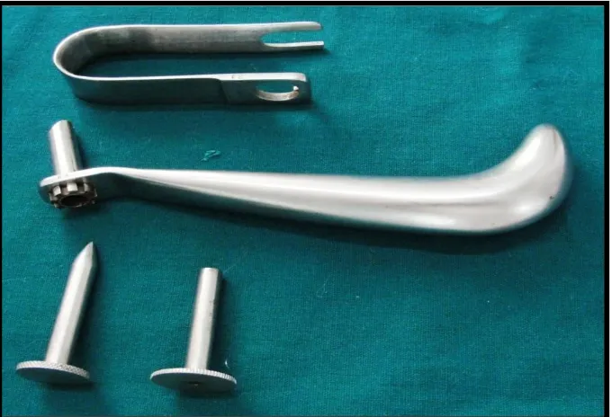
Armamentarium
Mouth mirror and probe
2% lignocaine with 1:100000 adrenaline
Periosteal elevator – Howarths and Molts
Erich’s arch bar
Stainless steel wire – 26 gauge
Wire twister
Wire cutter
Bard parker handle no 3
Blade no – 15
Transbuccal trocar and cannula
3- Dimensional titanium miniplate – 8 hole
2mm x 6mm , 2mm x 8mm monocortical titanium screws
Langenback retractor
Mosquito forceps
Plate bender
Drill bit – 1.5mm diameter
Micromotor and straight handpiece
Screw driver
Screw holder
Needle holder
36
Surgical Technique
Nasoendotracheal intubation was done. Patient was prepped and draped. Throat pack was placed. Using 2% lignocaine with 1:100000 adrenaline, infiltration was given in the buccal vestibule near the fracture site.
A curvilinear incision was made in the buccal sulcus extending from the mesial of 1st molar to the distal of the 3rd molar with the help of BP blade no 15.Subperiosteal dissection was done and the fracture was exposed and reduced. The patient was put into MMF and the occlusion stabilized. A 3- dimensional miniplate was then adapted over the reduced fracture in such a
way that the vertical bars were aligned perpendicular to the external oblique ridge. It was then secured with 2mm x 8mm monocortical titanium screws over the tension band zone according to Champy’s line of osteosynthesis..The
upper screws in the plate were placed first by direct access. The maxillomandibular fixation was then released for adequate access. This was
followed by a 6 to 8 mm stab incision made extraorally at the angle of mandible corresponding to the fracture site. With the help of a transbuccal
trocar a stab wound wasmade through the skin incision which communicated intraorally. A 1.5mm diameter drill bit was then passed through the transbuccal cannula to create holes for securing the plate with screws. After
37
closed with 5-0 proline. Throat pack was removed and patient was extubated.
Extraoral pressure dressing was applied.
All the patients were maintained under antibiotic coverage.
Intravenous antibiotics were given for two days followed by 3-5 days
of oral antibiotics. Injection dexamethasone was given 8mg BD for two days and stopped without tapering.
Fluids were advised for the first day and soft diet subsequently for 2-3
weeks. Gradually the diet was shifted to solid as per comfort of the patient.
Post operative follow up:
All the patients were evaluated on the 1st post op day, at the end of 2 weeks, 6weeks, 3months, and 6 months respectively. The following parameters were assessed:
Derangement of occlusion
Neurosensory deficit
Mouth opening
Infection
Loosening of screws
38
FINITE ELEMENT ANALYSIS OF 3-D PLATING
SYSTEM IN MANDIBULAR ANGLE FRACTURE
FIXATION
To evaluate more about 3 D miniplate in different clinical situations, a
Finite element study was carried out on a mandibular angle fracture model. The biomechanical behavior of 3 D plate, mandible and exact stresses in the
bone were measured after application of bilateral masticatory load. Following cases were evaluated:
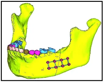
Design no1 - Fracture line distal to mandibular 2nd molar, from the
alveolar crest to and through the lower border stabilized with
3-Dminiplate. (fig.5)
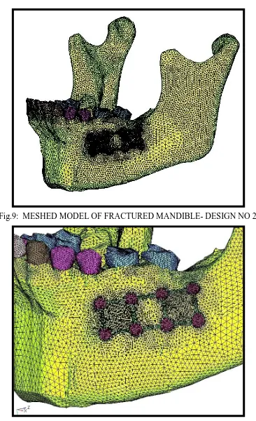
Design no2 - Fracture line between mandibular 1st and 2ndmolar, from the
alveolar crest to and through the lower border stabilized with 3- D
miniplate. (fig.6)
Design no 3 - Fracture line distal to mandibular 2nd molar, from the
alveolar crest to and through the lower border not stabilized with any
plate.
39
STEP 1 - CT SCAN AND DESIGN OF 3-DIMENSIONAL MANDIBLE MODELS
Computerized tomography data were obtained from a Siemens Somatome Sensation Multislice for a full human skull at every 1.0 mm in the horizontal plane. The data were from a 22 year old male who had full dentition
and normal occlusion. The CT data were then imported into CAD based medical software Mimics (Materialise, Belgium) in image format in order to
convert the scans into a suitable format for importation into any FEA/CAD program. Manual editing was then done in order to separate the dentate
mandible from the skull data.
STEP 2
The geometric models of the 3- D plate and screws were modeled
using Solid Edge 2004Software by using reverse engineering technique (measuring the dimensions of the brackets using precision tools).
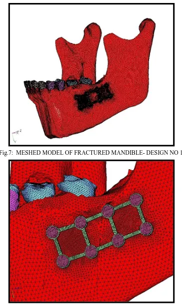
STEP 3 - CREATION OF FEA MODEL
The geometric models (surface and line data) were then imported into Hypermesh software for meshing. The process of converting geometric model
40
The volumes created for cortical bone, cancellous bone, dentin and
Speriodontal ligament were meshed using tetrahedral shaped solid
elements.
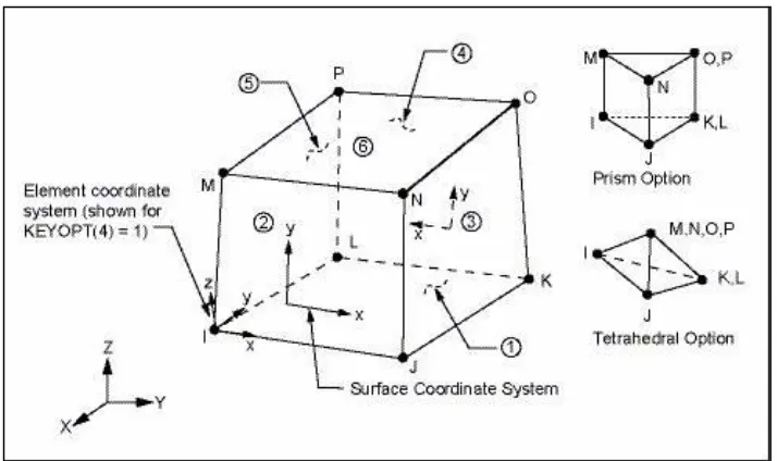
ELEMENT TYPE USED (4-NODED TETRAHEDRAL ELEMENT)
Solid45 element description
SOLID45 is used for the 3-D modeling of solid structures. The element is defined by eight nodes having three degrees of freedom at each node:
[image:47.595.120.477.410.622.2]translations in the nodal x, y, and z directions. The element has plasticity, creep, stress stiffening, large deflection, and large strain capabilities.
41
NODES AND ELEMENT DETAILS
No. of elements No. of nodes
DESIGN NO 1 614358 121491
DESIGN NO 2 599625 119564
DESIGN NO 3 581973 116783
STEP 4
Two fracture lines were created as mentioned earlier and then the segments were stabilized using 3- dimensional Plate and monocortical screws
STEP 5
Assembled finite element model of the Fractured Mandible with plate
and screws was then imported into Ansys 12.1 software for analysis. Pre-processing, solving and post-processing are three stages in Ansys.
STEP 6 – PRE- PROCESSING STAGE
Elastic material properties used in the finite element model were Young's modulus& Poisson's ratio.
Young’s Modulus / Elastic Modulus / Modulus Of Elasticity– It is a
measure of the relative stiffness or rigidity of a material within its elastic
range.
E (elastic modulus) =
Poisson’s Ratio- It is a ratio of lateral to the axial strain, within the elastic
range.
42
Each material was defined as homogenous and isotropic. The physical properties of the constituent materials comprising the model were based on
previous studies.41
These material properties (young’s modulus and Poisson’s ratio) of the
Dentine, Cortical bone, cancellous bone, PDL, Plate and Screws were entered in the pre-processing stage.
STEP 7
The loads and boundary conditions were applied in the solution stage. Elastic Modulus
(Mpa)
Poissons ratio (in
%)
Cortical Bone 13800 0.26
cancellous Bone 345 0.31
Dentine 18600 0.31
PDL 50 0.45
43
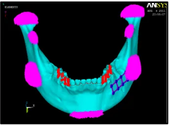
Boundary conditions: (fig.11)
The mandible was restrained from movement in all directions during
mastication. Seven regions including the condyle, coronoid processes, angle and the mandibular symphysis were fixed to zero displacement.
Applied Loads: (fig.12)
Biting force of 480N on premolar region and 660N on molar region was been applied. All these forces are acting along the vertical direction (long
axis of the tooth).
STEP 8 - SOLVING STAGE
Each load case was solved separately.
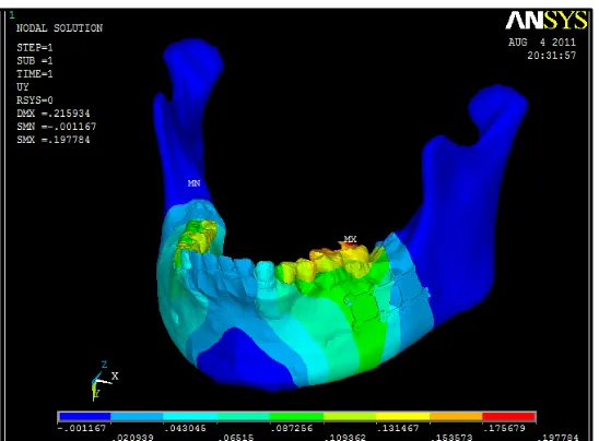
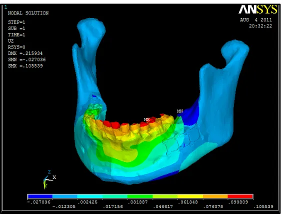
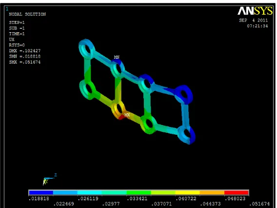
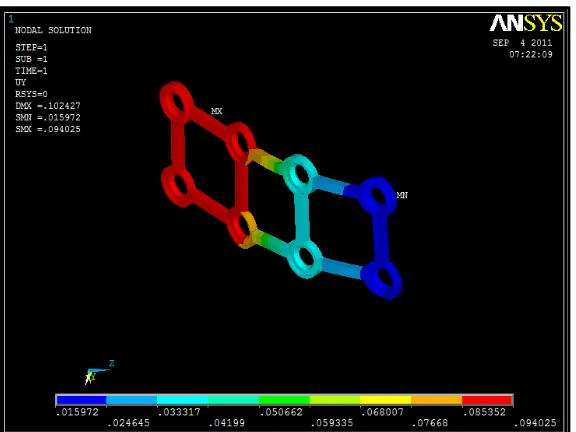
STEP 9 –POST PROCESSING STAGE
The results were post processed and the displacement and von-misses
stress contours of each individual parts in the system were captured.
Evaluation of stresses:
All stress values were a measure of von misses stress recorded in MPa
(Mega Pascal).
Von Misses Stress: It refers to a theory called the "Von Misses - Hencky criterion for ductile failure".
In an elastic body that is subject to a system of loads in 3 dimensions, a
44
within the body there are stresses acting in different directions, and the
direction and magnitude of stresses changes from point to point.
The Von Mises criterion is a formula for calculating whether the stress
combination at a given point will cause failure.
There are three "Principal Stresses" that can be calculated at any point,
acting in the x, y, and z directions. The x,y, and z directions are the "principal
axes" for the point and their orientation changes from point to point. The Von
Misses criteria is a formula for combining these 3 stresses into an equivalent
stress, which is then compared to the yield stress of the material. (The yield
stress is a known property of the material, and is usually considered to be the
Failure stress.)
The equivalent stress is often called the "Von Misses Stress".
Basically, it is not a stress, but a number that is used as an index. If the "Von
Misses Stress" exceeds the yield stress, then the material is considered to be at
the failure condition.
Following areas von mises stresses were measured:
1. Von mises stress distribution on 3- D miniplate 2. Von mises stress distribution on individual screws
3. Von mises stress in cortical bone around plates & screws 4. Von mises stress in cancellous bone around plate & screws 5. Von mises stress in the mandible
45
Measurement of deformation / displacement:
Amount of deformation / displacement was measured in mm for the
following regions:
1. 3-D miniplate plate
2. Screws 3. Cortical bone 4. Cancellous bone
5. Periodontal ligament 6. Full mandible
Software details
Ct scan of the mandible was taken into MIMICS SOFTWARE.
Mimics software allows to process and edit 2D image data (CT, μCT,
MRI, etc.) to construct 3D models with the utmost accuracy, flexibility and user-friendliness. The powerful segmentation toolsallows to segment medical
CT/MRI images, take measurements and engineer directly on 3D model. From there we can export our 3D data to a wide range of output formats and engineering applications; such as FEA, design, surgical simulation, additive
manufacturing and more.
In this study, CT data was imported into CAD based medical software
46
Surface data of the mandible, plate and screw generated using solid
edge 2004 software.
Finite element model generated using Hypermesh 9.0 software.
Analysis was carried out using ANSYS 12.1 SOFTWARE.
ANSYS is a finite element analysis (FEA) code widely used in the
computer-aided engineering (CAE) field.
This software allows to construct computer models of structures,
machine components or systems; apply operating loads and other design criteria; and study physical responses, such as stress levels, temperature
distributions, pressure, etc. It permits an evaluation of a design without having to build and destroy multiple prototypes in testing. It is modularised as a standalone software package with three fundamental modules. They are
preprocessor, solution and general postprocessor modules.
Color coding for stress
Blue - minimum stress
red - maximum stress
in between shades - variation of stress from minimum to maximum
Color coding for displacement
Blue - minimum stress
47
in between shades - variation of displacement from minimum to
maximum
Hardware details
Intel core 2 duo processor
4GB ram
320GB hard disk
Directions in which deformation occur
X—-- mesio-distal direction
Y---- Axial / vertical direction
Z---Bucco-lingual direction
Z
X
Fig.2: 8 HOLE 3D MINIPLATE
Fig.6: DESIGN NO 2- FRACTURE LINE BETWEEN MANDIBULAR 1ST
[image:56.595.123.463.419.685.2]Fig.11: BOUNDARY CONDITIONS
B
C
3
1
2
5
6
Fig.82: TRIANGULAR MEMBRANE ELEMENT ABC WITH
THREE NODES (A, B AND C), THREE BORDERS AND SIX DOF
Fig.83: ONE DIMENSIONAL ELEMENT
1
2
F
1- top fixed node –
restrained degree of
freedom
2 - bottom free node
- unrestrained
degree of freedom
F – tensile load
Fig. 87: DEGREE OF FREEDOM- 12
Fig.88: BOUNDARY CONDITIONS
+X -X
48
RESULTS
6 patients with mandibular angle fracture, reporting to the department
of oral & maxillofacial surgery, Ragas Dental College & Hospital, Chennai from september 2009 to September 2010, requiring open reduction and internal fixation were selected for the study.All the patients were
systematically monitored until 1 year post operatively
Demographic details of the patients were recorded. All the patients
were males of the third and fourth decade.They were fully dentulous. They presented with horizontally unfavourable mandibular angle fracture. Interpersonal violence was the most comman etiology followed by road traffic
accident. A concomitant fracture was present in 3 patients. The second most comman fracture was at the contralateral parasymphysis. In 4 patients, there
was a third molar tooth in the line of fracture. In 2 of these patients, the tooth had to be removed to help aid reduction of fracture and its subsequent
stabilization.
None of the patients developed wound dehiscence or infection postoperatively. Nosegmental mobility was detected clinically. Adequate
mouth opening was present for all the patients at last follow up visit. Four out of six patients had satisfactory postoperative occlusion while two patients had mild derangement of occlusion present. All but one patient had normal sensory
49
dysesthesia at the lower lip region on the same side as the fracture. This patient presented with paresthesia preoperatively. Radiographically, no
hardware related complications like plate fracture were seen.Plate removal has not been necessary in any of the patients till date.
MASTER TABLE.1
OUTCOME VARIABLES
PATIEN T NO 1
PATIENT NO 2
PATIENT NO 3
PATIEN T NO 4
PATIEN T NO 5
PATIEN T NO 6
Occlusion at
last follow up intact deranged deranged intact intact intact
Clinical union at last
follow up
present present present present present present
Neurosensory
deficit Absent Absent Absent Present Absent Absent
Final interincisal
dimension
46 mm 36mm 50mm 47mm 48mm 49mm
Infection Not
present
Not
present Not present
Not present Not present Not present Hardware failure Not present Not
present Not present
RESULTS OF FINITE ELEMENT ANALYSIS
DESIGN NO 1
MASTER TABLE.2
MASTER TABLE.3 COMPONENT
VON MISSES STRESS (IN Mpa)
Max Min
3-D plate
296.467 795E-03
Screws
125.87 0
Full model
296.467 .000795
Periodontal ligament
5.103 0.023
Cortical bone
216.015 .005548
Cancellous bone 32.885 0.005
COMPONENT
DEFORMATION IN X – AXIS
(in mm)
DEFORMATION IN Y – AXIS
(in mm)
DEFORMATION IN Z – AXIS
(in mm)
Max Min Max Min Max Min
3-D plate
.051674 .018818 .094025 .015972 .035711 -.01325
Screws
.057284 .018594 .116047 .01651 .036704 -.012069
Full model
.076133 -.043442 .197784 -.001167 .105539 -.027036
Periodontal ligament
0.07 -0.02 0.18 0.02 0.09 -0.00
Cortical bone
0.076 -0.020 0.143 -0.001 0.094 -0.027
Cancellous bone
DESIGN NO 2
MASTER TABLE.4
COMPONENT
VON MISSES STRESS (IN Mpa)
Max Min
3-D plate
379.699 3.447
Screws
157.117 0.00
Full mandible
379.699 .005572
Periodontal ligament
5.243 0.016
Cortical bone
112.051 .005572
Cancellous bone 9.608 0.005
MASTER TABLE.5
COMPONENT
DEFORMATION IN X – AXIS
(in mm)
DEFORMATION IN Y – AXIS
(in mm)
DEFORMATION IN Z – AXIS
(in mm)
Max Min Max Min Max Min
3-D plate
.054118 .001742 .102388 .038588 .030269 -.00872
Screws
.064981 .002575 .122705 .039048 .032606 -.0132
Full mandible
.081727 -.051977 .177222 -.001826 .106233 -.050044
Periodontal ligament
0.082 -0.028 0.177 0.011 0.099 -0.049
Cortical bone
.076 -0.028 0.146 -0.002 0.099 -0.050
Cancellous bone