University of Southern Queensland
Faculty of Engineering and Surveying
Dragline Maintenance Engineering
A dissertation submitted by
Bruce Thomas Jones
in fulfilment of the requirements of
Courses ENG4111 and 4112 Research Project
towards the degree of
Bachelor of Engineering (Mechanical)
ABSTRACT
This research project ‘Dragline Maintenance Engineering’ explores the maintenance strategies for large walking draglines over the past 30 years in the Australian coal industry.
Many draglines built since the 1970’s are still original in configuration and utilize original component technology. ie electrical drives, gear configurations. However, there have been many innovative enhancements, configuration changes and upgrading of components
The objective is to critically analyze the maintenance strategies, and to determine whether these strategies are still supportive of optimizing the availability and reliability of the draglines.
The maintenance strategies associated with dragline maintenance vary, dependent on fleet size and mine conditions; they are aligned with the Risk Based Model. The effectiveness of the maintenance strategy implemented with dragline maintenance is highly dependent on the initial effort demonstrated at the commencement of planning for the mining operation.
University of Southern Queensland
Faculty of Engineering and Surveying
ENG4111 & ENG4112 Research Project
Limitations of Use
The Council of the University of Southern Queensland, its Faculty of Engineering and Surveying, and the staff of the University of Southern Queensland, do not accept any responsibility for the truth, accuracy or completeness of material contained within or associated with this dissertation.
Persons using all or any part of the material do so at their own risk, and not at the risk of the Council of the University of Southern Queensland, its Faculty of Engineering and Surveying or the staff of the University of Southern Queensland.
This dissertation reports an educational exercise and has no validity beyond this exercise. The sole purpose of the course pair entitled “Research Project” is to contribute to the overall education within the student’s chosen degree program. This document, the associated hardware, software, drawings, and other material set out in the associated appendices should not be used for any other purpose: if they are so used, it is entirely at the risk of the user.
Prof F Bullen Dean
Certification
I Certify that the ideas, designs and experimental work, results, analyses and conclusions set out in this dissertation are entirely my own effort, except where otherwise indicated and acknowledged.
I further certify that the work is original and has not been previously submitted for assessment in any other course or institution, except where specifically stated.
Bruce Thomas Jones
Student Number: 0039340337
_______________________________ Signature
ACKNOWLEDGEMENTS
Appreciation is given to the following groups for information and materials used in this project.
BHP Billiton Mitsubishi Alliance (BMA)
Maintenance Technical Institute (MTI) - Monash University
Center for Mining Technology and Equipment (CMTE) – University of Queensland
Table of Contents
1 Introduction ...8
1.1 Study Outline ...8
1.2 Introduction ...8
1.3 The Problem ...8
1.4 Research Objectives ...9
1.5 Conclusions: Chapter 1. ...9
2 Literature Review...10
2.1 Introduction ...10
2.2 Literature: Recent Decade...10
2.3 Literature: Previous Decades ...13
2.4 Conclusions: Chapter 2 ...15
3 Dragline Overview ...16
3.1 Introduction ...16
3.2 What Is A Dragline ...16
3.3 How Does It Operate...17
3.4 Where It All Stared ...18
3.5 Geographic Location...19
3.6 Conclusions: Chapter 3 ...20
4 Major Maintenance Shutdowns...21
4.1 Introduction ...21
4.2 Strategy ...21
4.3 Planning ...23
4.4 Execution ...25
4.5 Close out ...26
4.6 Recommendations: Chapter 4 ...27
4.7 Conclusions: Chapter 4 ...27
5 Dragline Configuration ...29
5.1 Introduction ...29
5.2 Manufacturers ...29
5.3 Boom Configurations ...30
5.4 Walking Mechanisms...33
5.5 Universal Dig Dump (UDD)...34
5.6 Recommendations: Chapter 5 ...36
5.7 Conclusions: Chapter 5 ...37
6 Structural Integrity ...38
6.1 Introduction ...38
6.2 Tub ...38
7.4 Power Control Systems ...46
7.5 Recommendations: Chapter 7 ...47
7.6 Conclusions: Chapter 7 ...47
8 Mechanical Advancements ...48
8.1 Introduction ...48
8.2 Structural Components...48
8.3 Bearings ...50
8.4 Gear Developments...52
8.5 Recommendations: Chapter 8 ...55
8.6 Conclusions: Chapter 8 ...55
9 Conclusions Chapter ...57
9.1 Introduction ...57
9.2 Discussion ...57
9.3 Further Work...58
9.4 Statement - Project Objective...59
10 References ...60
11 Appendices...63
11.1 APPENDIX A - Project Specification ...64
11.2 APPENDIX B – BMA Dragline Time Usage...66
1 Introduction
1.1 Study Outline
The need for this research project was identified from both personal observations within the coal mining industry, and available literature discussing the dynamic changes in maintenance practices in large plant and equipment. Draglines are unique pieces of equipment that have evolved through the development and introduction of new technology, operating practices and mining methods. The purpose and scope of this study is detailed in 1.4 Research Objectives
1.2 Introduction
When draglines were introduced into the coal industry the maintenance strategies were initially developed and introduced by the equipment suppliers. Over the following two decades the mining companies (in association with engineering consultancies) went through a period of improving work practices to optimise the equipment availability and reliability. Much of the work over this twenty year period had been documented through papers and journals available through databases. Although, there has been some excellent research work in the recent ten years in identifying and discussing maintenance strategies in plant and equipment, only few could be found specific to dragline applications.
1.3 The Problem
Despite the current strategies for draglines being embedded in the mine site maintenance systems there is evidence that dragline performance is reduced and below the expectations of mining companies. BHPBilliton Mitsubishi Alliance (BMA) who owns the largest fleet (47) in Australia identified that dragline usage has declined in recent years (Appendix B) and during a dragline optimization workshop identified deficiencies in productivity of their dragline fleet (Appendix C).
1.4 Research Objectives
The aim of this project was to review and critically analyze the maintenance strategies, and determine whether these strategies were still supportive of optimizing the availability and reliability of the draglines.
The research methodology was to identify specific areas of developed improvements in dragline operations and to discuss each as a sectioned chapter. Each chapter closes with a conclusion section based on the interpretation of the information gathered within the timeframe of the project.
Recommendations to introduce concept improvements to dragline maintenance are included in chapter four (4) through to eight (8).
The discussion within the chapters aligns with the objectives of the project specification (Appendix A).
1.5 Conclusions: Chapter 1.
This dissertation aims to discuss previous research work associated with dragline maintenance engineering, raise awareness of introduced new technology and configuration changes, and to add recommendation towards opportunities to improve maintenance strategy alignment.
The research is expected to result in a demonstration of how the basic theory of the maintenance strategy model is connected to the major component areas of the dragline.
The outcomes of this study will be used to educate engineers in the field of dragline maintenance engineering. It will provide the platform for future research to commence by giving a presentation of current practices specific to the operation of a dragline.
2 Literature
Review
2.1 Introduction
This chapter will review literature gathered to establish previous research into maintenance strategies, and developments in dragline maintenance engineering. It will provide engineers with a portfolio of documentation that can be referenced for future use.
The methodology used was to subdivide literature periods into groups. In the recent decade there has been many papers discussing changes in maintenance strategies and application of maintenance programs. There were several articles specific to structural issues on draglines and these were captured within later chapters.
Prior discussions on dragline maintenance reflected the opportunities to rebuild major components in the effort to extend component life and improve maintenance practices.
Each literature reference has comment on application within the dragline the scope of dragline operations.
2.2 Literature: Recent Decade
2.2.1 Set a Plan for Changing Conditions
Huber (2007) has identified that maintenance programs should have flexibility to allow for changing operational conditions. Environmental climate, pit conditions, material properties, and production pressures are areas Huber has identified that can have an effect on the maintenance program.
This article has given a simple overview of issues that should be considered when monitoring a maintenance program for equipment in an open pit mining situation. As conditions change additional wear, stress or operational characteristics of equipment may be experienced requiring an adjustment in the maintenance schedule of components. Reducing or extending the interval of inspection may be the outcome.
2.2.2 Fracture mechanics of mining dragline booms
Dayawansa et al. (2006) discusses the structural cracking associated with tubular boom design draglines. There is a regular cracking phenomenon at the welds which means the cracking must be remotely detected, exactly located and repaired.
The paper describes the cracking that occurs in the weld joints, the protection system in place to prevent catastrophic boom failure, and the maintenance and repair techniques used to keep the boom in an operational condition.
2.2.3 A review on machinery diagnostics and prognostics implementing condition – based maintenance
Jardine et al. (2006) summarise and review the recent research and developments in diagnostics and prognostics of mechanical systems implementing condition-based maintenance (CBM). CBM is a maintenance program that recommends maintenance decisions based on the information collected through condition monitoring.
Condition monitoring has three main steps: data acquisition, data processing and maintenance decision making. Realising the increasing trend of using multiple sensors in condition monitoring the authors discuss different techniques for multiple sensor data fusion.
Condition monitoring is used extensively on draglines major components. Vibration analysis, magnetic particle testing and infra red imaging are the data acquisition steps.
2.2.4 Dynamic modelling of the tradeoff between productivity and safety in critical engineering systems
Cowing et al. (2004) present and illustrate a dynamic probability model designed to describe the long term evolution of a maintenance system that takes into account both productivity and safety. They discuss the different phases of operation, shutdown and possibly accident. The models parameters represent explicitly the effects of different component’s performance systems, allowing for safety and reliability through an engineering probabilistic risk assessment.
There have been historic examples of catastrophic failures involving dragline structural components. Boom and mast failures, suspension rope failures and revolving frame failures have impacted both the production and safety environments. Early identification and assessment of potential interruptions to production mitigates the risk of these failures occurring.
2.2.5 Zinc Alloy Outperforms Bronze In Dragline Bearing Test
Sae 660 bronze which shows that they do have advantages in tensile strength, yield strength, and hardness.
2.2.6 Models for maintenance optimization: a study for repairable systems and finite time period
Crespo Marquez and Sanchez Heguedas (2002) discuss the implementation of the maintenance model. They present a selection process for a suitable maintenance policy for repairable systems and for a finite time period.
Since the late seventies, examples of models assessing corrective and preventative maintenance policies over an equipment lifecycle exist in literature. However, there are not too many contributions regarding real implementation of these models in industry
2.2.7 Dragline field testing
Guan (2001) has described the field test utilised to capture the dynamic behaviour exhibited on a specific dragline boom during operation. Multiple accelerometers were installed on the boom and mast to capture data as three methods of excitation were used during normal operation.
The aim of the modal testing was set to explore the six global modes for the boom structure and present results.
2.2.8 Systems integration in maintenance engineering
Starr and Ball (2000) introduce and discuss systems associated with maintenance engineering. By demonstrating that maintenance decisions are made in the context of business priorities; they show that the bidirectional flow of data and information into the decision making planning is essential at all levels.
They present how decision making is often achieved with uncertainty and unknowns, while measuring against conflicting performance criteria.
2.2.9 Maintenance Modelling for Computer-based systems
Meshkat, Dugan and Andrews (2001) have used the example of a simple water deluge system to model a maintenance plan that involves failure driven and time driven modes of integrated components. It is important to note that this is for a system that is predominately in standby mode.
2.2.10 Modern design concepts provide high production on new generation P&H walking draglines
Backus (1997) discusses how P&H Mining (dragline manufacturer) are meeting the demands of customers in the dragline market. High capital cost and the demand for a high rate of return for the investment from the customer requires the Original Equipment Manufacturers (OEMs) to provide machines with more range and bucket capacity without a commensurate increase in weight and cost. He discusses the demands by the users requiring better access to components for inspection and maintenance as well as improved diagnostic capability to keep maintenance and repair downtime to a minimum.
2.3 Literature: Previous Decades
2.3.1 Proceedings of the international Symposium on Risk, Economy and safety, failure Minimisation and Analysis – Failures 94
Nichols et al. (1995) have presented articles containing references to the assessment of critical dragline boom suspension components, the fatigue failure of deck support beams, the evaluation of steel structures load carrying capacity, and the fracture mechanics of beams.
Some material is not directly related to the dragline field although much of the theory could be applied in areas of research.
2.3.2 Dragline tub and roller circle repairs
Herringe and Fry (1992) discuss the drivers for major maintenance shutdowns on draglines. Draglines have been in service for over 30 years and many are / have reached an age where maintenance and downtime costs are prohibitive, and decisions need to be made to either replace or refurbish them. Refurbishment is the popular economic choice and this usually involves major structural repairs above and below the roller circle.
Planning of the major repairs involve what should be done in the repair? What aspects of dragline design should be improved in the repair? What components should be replaced?
2.3.3 New Developments in high productivity excavators
Ehret and Haase (1992) discuss some of the innovations of the period with improving dragline productivity. The Marion 8000 series draglines were the focus of the paper.
Areas of development have been in the base frame roller frame, front end geometry modifications, right weight buckets, planetary swing drives, and high voltage generators.
2.3.4 Rehabilitation of a large walking dragline
Joubert (1986) has reviewed the preparation and planning of a dragline rehabilitation project, the first attempt in the world to refurbish a Marion 8000 series. The project illustrates how a 14 year old dragline can be effectively repaired and modified at 10 per cent of its replacement cost.
2.3.5 Erection and commissioning of the worlds first 122 metre long boom, large capacity dragline
Hill (1984) has detailed the erection and commissioning of the first 122m length boom dragline emphasising the new mast and boom design of the period. He provides a brief look at the development of the coal mining industry in Canada and the differing conditions which dictate the type of machinery required. He gives an explanation to the reasons behind the selection of this long boom configuration.
2.3.6 Non- Destructive Testing During The Construction & For The Preventative Maintenance of Draglines
Rollestone (1983) discusses the Non Destructive Testing (NDT) applied to three Marion 8050 draglines being constructed. In particular the inspection of welded critical structural sections during fabrication and assembly and the formulation and initiation of a preventative maintenance NDT program.
2.3.7 Use of Epoxy Grout in Supporting Dragline Slew Bearings
Chasling et al. (1981) discusses the use of a synthetic resin epoxy grout for the correction of slew bearing geometry located between the lower sub frame (tub) and the upper revolving frame. The reasons for a departure from traditional methods of repair are examined and tests are described which assess the suitability of the technique.
Historically to align the geometry of supporting rails machining of the contact faces was required. By using an epoxy grout the deviations within the mounting surfaces could be counteracted by setting the upper surfaces of the rails where the rollers contact to the required tolerances and then pumping grout between the supporting faces. This method reduces downtime and costs during major rebuilds.
2.3.8 Dragline Slew Bearings: Factors Affecting Their Life And Operation
2.3.9 Lubrication of Enclosed gearing on Large Shovels & Draglines Down (1969) discusses lubrication requirements for large gears and the factors that have to be considered. This includes their design, speed of operation, gear reduction ratio, nature of load, operating temperatures, input power and mechanical effects. The type of lubrication whether it be splash fed or circulating pumped as well as action of additive compounds on gear lubrication are also discussed.
2.4 Conclusions: Chapter 2
This literature review identifies papers that were readily available through search databases relating both to specific dragline listings and maintenance strategy documentation.
In the past decade the available research papers for draglines have predominately related to boom structural topics. Many papers relating to condition based maintenance developments and identifying changing conditions for maintenance programs were available, these were reviewed with the general topics being categorised and a sample used for referencing in this dissertation.
Early papers available reflected developments in maintenance practices with major shutdowns and identifying rebuild criteria for major components. The practices reviewed from these papers have become embedded in today’s maintenance strategies.
3 Dragline
Overview
3.1 Introduction
This chapter will describe to the reader an understanding of dragline history, how they operate, and the geographical locations in the Australian coal industry where they are utilised.
Its purpose is to provide the reader with the base knowledge of dragline operations so that the discussion provided in later chapters can be more easily comprehended.
3.2 What Is A Dragline
A dragline is a large piece of earthmoving equipment. It is predominantly used in mining operations but is also found on a much smaller scale in civil operations. The larger draglines are used in strip mining to remove the soil layers covering coal. The smaller machines may be used to de-silt canals and dams.
3.3 How Does It Operate
Large draglines that are used in the coal industry are powered by electricity. Due to their high consumption of power they are connected to the high voltage grid of the states power system; their supply voltage is 66 kV. This power supply is then reduced by internal transformers to power the electrical drive systems. The drive systems consist of generators and motors for each motion circuit. The motion circuits for a large dragline are hoist, drag, rotation (swing) and propel.
Inside the main house structure is a system of geared machinery driving large winch drums for the hoist and drag motions, these drums contain the hoist and drag ropes. Electric motors are directly coupled to the geared machinery. The drums pay the ropes in either a forward or reverse direction under the direction of the operator who is situated in a cab overlooking the bucket. This process creates the digging action (Fig 1.2). The operator manipulates hand levers to control the hoist and drag motions, while using foot pedals to control the swing direction of the upper frame to the base. The levers and pedals send electric signals to the main control panels for the electric drives.
Most draglines today have Programmable Logic Control (PLC) units to monitor and convert the signals coming from the operator into commands for the drive units. Other inputs from various transducers on the motions are fed into the PLC to assist in the control of the motions. There are still some draglines using old technology to control the drives rather than PLC, these however are becoming fewer as companies upgrade.
3.4 Where It All Stared
In 1904 John W Page (Page Schnable Contracting) invented the dragline to dig the Chicago canal in the USA. Initially the dragline had restricted mobility until John invented a walking mechanism a few years later. (www.personal.edu/staff)
In 1910 the company Bucyrus Erie entered the dragline market by purchasing manufacturing rights for a dragline excavator. Bucyrus Erie helped pioneer the introduction of electrically powered draglines into the mining industry.
In 1914 the company Harnischfeger Corporation entered the dragline market with their own gasoline powered model.
In 1939 the company Marion Steam Shovel Dredge Company entered the dragline market with its own version of the walking dragline.
In 1988 the Page company rights were acquired by the Harnischfeger Corporation and marketed their draglines under the line of “P&H” draglines.
In 1997 Bucyrus (Erie later dropped) acquired the rights of the Marion Steam Shovel Dredge Company.
3.5 Geographic Location
Draglines are located in both the Queensland and New South Wales coal mining districts; the majority (57) are based in the Bowen Basin region of Queensland and a lesser (14) in the Hunter Valley region (HVC 2005).
Bowen Basin Region – Queensland
3.6 Conclusions: Chapter 3
Draglines are unique pieces of equipment that have had a long history of evolution in the earthmoving sector. They move very efficiently large volumes of material compared to alternative strip methods.
The dragline is comprised of multiple electrical and mechanical systems that must be integrated together to allow the digging and dumping cycles. New control system technologies are being introduced to improve machine reliability.
Company acquisitions have consolidated dragline suppliers so that there are two companies supplying to the Australian market, the coal mines utilising draglines are located in Queensland and New South Wales.
4 Major Maintenance Shutdowns
4.1 Introduction
This chapter introduces the concept of the major maintenance shutdowns. The strategy model, of which maintenance is based is discussed and leads into the planning, execution and close out cycles of the major shutdown. The intent is to demonstrate the complexity of aligning the maintenance requirements, the relevant component strategy model and the planning detail.
The majority of draglines in the Australian coal industry have been in service in excess of twenty (20) years, some over thirty (30) years. Many are / have reached an age where maintenance and downtime costs are prohibitive, and decisions need to be made to either replace or refurbish them. Refurbishment is the popular economic choice and this usually involves major structural repairs above and below the roller circle (Herringe and Fry 1992).
To enable the major structural repairs to be carried out, sufficient out of service downtime is required to enable the completion of works; these outages may vary from one (1) week up to ten (10) weeks, dependent on the scope of works. The frequency of the major shutdowns varies between one (1) year and five (5) years. The associated downtime must be factored into the whole of life cycle planning so that total operational profitability of the dragline asset can be understood.
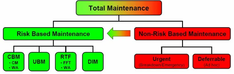
4.2 Strategy
CBM – Condition Based Maintenance UBM - Usage Based Maintenance RTF – Run To Failure DIM – Design Improvement Maintenance CM – Condition Monitoring WA – Work Arising
[image:22.612.121.529.98.228.2]FFT – Failure Finding Task
Fig. 3.1
Risk Based Maintenance Model
Condition based maintenance utilises inspection and monitoring tools to access the condition of components, the evaluated condition of the component then drives the change out schedule for the specific component.
Usage based maintenance is reliant on scheduled change out intervals; this may be either time or productivity driven. eg. A gear case may have all bearings changed once they have achieved thirty (30) thousand service hours in use, or a bucket may be due for change out after it has moved five (5) million banked cubic metres (BCMs) of material. Design improvement maintenance runs parallel to both condition and usage based maintenance plans. Opportunities for improvement that are identified during the life cycle go through an engineering review and development process, once developed they will be implemented during the next scheduled shutdown and then be monitored for value and effectiveness.
A single dragline mine site may use a predominantly condition based strategy over a usage based strategy to maximise dig time. This requires a much higher level inspection regime due to the criticality of the dragline in the overall mine plan.
in multiple shutdowns being completed per site per year to maintain alignment. With a recent requirement to re capitalise draglines during shutdowns it was necessary to re evaluate the five (5) year strategy. The capital cost per shutdown can impact the overall mine capital plan, which becomes part of the overall business strategy. To offset the multiple capital costs that may fall in one financial year the impact of extending the shutdown interval is under review.
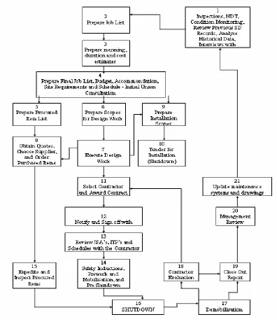
4.3 Planning
Planning for a major shutdown can start immediately after the previous shutdown or there may be several mini shutdowns integrated into an overall major shutdown plan. The complexity of tasks and large costs involved in a major shutdown determine the level of detail of planning, a flowchart is used to standardise the planning process between shutdowns (Fig. 3.2).
Contract labour is used on shutdowns due to the peaked manning numbers involved; the mines are not sufficiently resourced to maintain the continuity of work.
Fig. 3.2
An inadequate scope will introduce a cost risk factor with the contractor, be ambiguous about who pays if a dispute occurs, often result in a significant cost / variation, and runs the risk of lengthening the shutdown duration.
Parts procurement for a shutdown can start up to three (3) years prior to the shutdown; this is due to the lead time delivery of the items. The availability of base materials (eg.steels) and the workshop capacity of major fabricators have driven this requirement. The manufacture of major gearing can take in excess of two (2) years to supply parts once a purchase order is placed. There are limited workshops in Australia with the capacity to fabricate many of the large items associated with draglines; this creates a work loading issue and potential bottleneck when draglines from multiple companies have overlapping shutdown schedules.
Risk assessments are conducted for the critical items during the planning process. The risks are assessed and contingency plans drawn up for the events which would constitute a major risk to the shutdown progressing on schedule and within budget.
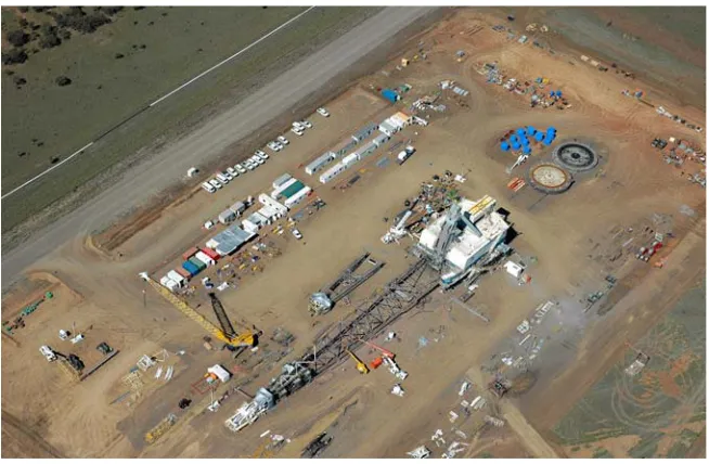
4.4 Execution
[image:25.612.174.501.445.659.2]The execution of a dragline shutdown is a significant event in the life cycle of the asset. The intensity of multiple complex tasks being performed during a relatively small period of time, and the scheduling of resources and equipment required generate an increased reliance on having capable management controlling the shutdown site (Fig. 3.3).
Fig. 3.3
The shutdown execution is carried in a systematic manner that follows a detailed work program (Gannt Chart). The program identifies the interdependencies of multiple tasks and critical path networks. The activities within the program are completed over a twenty four (24) hour continuous operation, supervision is critical in maintaining continuity of work. A detailed reporting method is used to capture progress that is then relayed back into the program.
[image:26.612.129.530.268.540.2]Daily meetings are held to track progress (Fig. 3.4) and ensure that that all procured items are available for impending tasks. The progress schedule and procured item list form the basis for this meeting along with reviews of the scope of works.
Fig. 3.4
Progress curve used for the tracking of the dragline shutdown
Quality assurance documents detailing inspection test results of components inspected, dimensions of new parts installed, and compliance to relative Australian Standards stipulated in the scope of works are collated for future reference.
Critical item drawing registers are updated as part of the close out phase. Electrical schematics, major modifications and component upgrades are captured in the documentation.
4.6 Recommendations: Chapter 4
1. Create a matrix spreadsheet sheet detailing component item and associated maintenance strategy, a single source for this information could not be identified. The proposed benefit of this is better alignment of components in the long term planning of shutdowns by assisting to identify the change over points between a usage base strategy model and a condition based model.
2. Perform a breakeven analysis into the commercial decisions of major shutdowns reflecting the influence of the change over point for multiple dragline sites to utilise a specific model. As the usage based model is used on multiple draglines sites there was no minimum number of draglines on a site identified before a usage based model was most effective.
3. Initiate a peer group review on the final shutdown execution schedule; this would create a benchmark alignment between mine sites and an opportunity to share practices and to identify best practice.
4.7 Conclusions: Chapter 4
This chapter has demonstrated that the maintenance shutdown of a dragline is a major event in the life of a key mine asset. Economic factors must be considered when determining the duration and frequency of works.
Mine size and asset numbers drive the maintenance strategies associated with maintenance shutdowns. A usage based strategy was identified as predominant for draglines during the research but this could be attributed to the large number of mines with multiple draglines on site.
The execution phase of the shutdown must closely follow a program schedule. The multiple dependencies of tasks within the schedule determine the overall duration of the shutdown. Considerable efficiencies are achievable by the manipulation of tasks and their respective links.
The close out report completes the loop of information and sets the foundation for the next shutdown. The quality of the information and detail of the report allows the commencement of the next budget draft.
The recapitalisation of draglines is emerging as an additional factor when scheduling the frequency of shutdowns.
5 Dragline
Configuration
5.1 Introduction
This chapter will introduce the manufacturers of draglines and several of their respective models available, and are in use in the Australian coal industry. The intent is to provide an overview of the component differences that can influence the selection of the most appropriate maintenance strategy.
A new innovation in dragline configuration will be introduced that involves the integration of old and new technology. New methods in maintenance planning and operations planning have resulted through the design changes.
5.2 Manufacturers
Bucyrus International Inc, are a global leader in the manufacture and supply of large walking draglines; they supply the market with the two (2) brands Marion and Bucyrus. The Marion range (Fig. 2.1) has 5 models ranging from 69m boom length, 21m³ bucket capacity and 1,780 tonne operating weight up to 121m boom length, 126m³ bucket capacity and 6,580 tonne operating weight. (www.bucyrus.com)
The Bucyrus range has 3 models ranging from 58m boom length, 12m³ bucket capacity and 1,000 tonne operating weight up to 128m boom length, 138m³ bucket capacity and 7,250 tonne operating weight.
[image:29.612.203.448.500.667.2]Harnischfeger Corporation (P&H) has 5 models ranging from 53m boom length, and 22m³ bucket capacity up to 129m boom length and 122m³ bucket capacity.
Fig. 2.1 - Marion 8050
The configurations of draglines are based on mine requirements. The depth of pit, spoil height and placement are key drivers in determining boom length, drum size and motion power requirements. Different mine conditions dictate the type of machinery required and configurations such as boom lengths (Hill 1984). OEMs are proactive in meeting the demands of customers in the dragline market. High capital cost and the demand for a high rate of return for the investment from the customer requires the OEMs to provide machines with more range and bucket capacity without a commensurate increase in weight and cost (Backus 1997).
The major component blocks of draglines are similar although the specific structural designs differ between the major OEMs. The two predominant visual differences between the dragline configurations are the boom designs and the external walking mechanisms.
Recent advances in technology outside of the OEM frame work have allowed the implementation of the Universal Dig Dump option for bucket control.
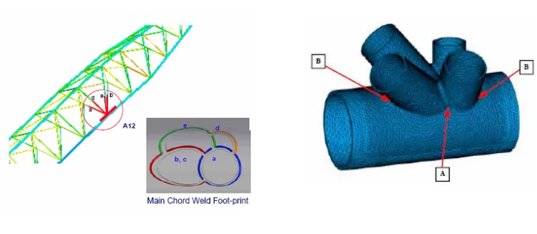
5.3 Boom Configurations
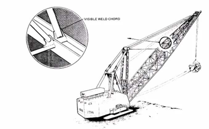
[image:30.612.132.510.504.669.2]The Marion and P&H booms are similar in structure utilising a four (4) main chord design with a rectangular cross section. The main chords are I beam wide flange sections; lacings connect the chords forming the lattice in both the vertical and horizontal planes. To minimize the possibility of structural failure in chords or cross lacing members, all welds and chord surfaces are visible for rapid and thorough field inspection (Fig. 2.3). The nodal connections differ significantly in design compared to the cluster design.
Fig. 2.3
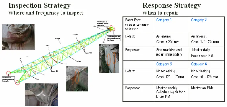
A catastrophic boom failure within the BHP Mitsubishi Alliance (BMA) group in the Bowen Basin region in central Qld prompted the initiation of an Inspection & Response strategy for all dragline booms within the BMA group; BMA has a fleet of 35 draglines. BMA worked in conjunction with the Monash University – Maintenance Technical Institute (MTI) to prepare documents identifying the specific critical areas of inspection, and a response strategy to faults identified (Fig. 2.4).
Fig. 2.4
5.4 Walking Mechanisms
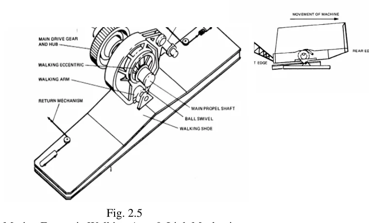
[image:33.612.199.579.250.480.2]The Marion and the P&H draglines utilise a similar walking mechanism. This consists of an eccentric articulated arm, which is supported by a shaft and bearings on both sides (Fig. 2.5). A link between the walking arm and the main frame stabilizes the eccentric motion. As the eccentrics rotate in the direction of travel, the walking shoes located on each side of the machine are lowered to the ground and as the eccentric continues to rotate the machine is lifted until only the tub (base) trailing edge (below boom) is in contact with the ground. With each eccentric motion the upper carriage is moved in relation to the ground, the distance (step) is approx 1.6m each rotation.
Fig. 2.5
Marion Eccentric Walking Arm & Link Mechanism
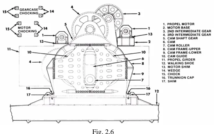
The Bucyrus machines utilize a cam arrangement also however the there is no stabilizer link as per Marion machines. A guide cam is mounted on the eccentric (Fig. 2.6) and runs within a guide. As the cam rotates the shoe is lifted and the guide controls the direction of the shoe.
Fig. 2.6
Bucyrus walking mechanism utilizing cam roller and guide
5.5 Universal Dig Dump (UDD)
The Universal Dig Dump (UDD) dragline concept was developed by the Centre for Mining Technology and Equipment (CMTE) in the 1990’s. The first machine upgraded with the UDD configuration was commissioned at Peak Downs mine in Qld in 2002.
(Fig.2.7), the ability to dump material up to 40M inside boom point which allows for more efficient bench bridge preparation, and an increase in available dump height.
Fig. 2.7
Bucket Rigging Comparison
The UDD arrangement has since been installed to both Bucyrus and Marion booms. The UDD configured machines differ in the boom point arrangement. The conventional dragline boom point consists of the hoist rope sheaves concentric to each other utilising the same shaft. The UDD sheaves are mounted on separate shafts in the same vertical plane but one is behind the other, this allows the ropes to attach at each end of the bucket.
Fig. 2.8
Bucyrus 1370 floor plan showing UDD machinery
5.6 Recommendations: Chapter 5
1. Install strain gauges at key critical elements of the booms and masts to allow real time monitoring of induced stresses during operation. The intent is to be able to control digging capacity by induced stresses rather than the current situation where control is based on maximum payload. This will allow optimising the digging ability of the boom against it design criteria. MTI have documented critical elements and formulated response strategies so the monitoring points can be identified. Apart from monitoring fatigue index’s in booms from strain gauging there has not been documentation found where this concept has been progressed.
2. Investigate and trial composite polymers that may be suitable for sheaving the
O LD
N E W
“Front” R ope D rum
3. Initiate a trial of alternative open gear lubricants on the walking mechanisms. Using one side as a standard for reference, an alternative would be used on the opposite side; monitoring both by thermography on sliding surfaces and motor current would allow the data to be tabled for analysis.
5.7 Conclusions: Chapter 5
The effectiveness of the maintenance strategy implemented with the choice of dragline configuration is dependent on the initial effort placed at the start of planning for the mining operation. Boom length and bucket size determine many inspection regimes that are initiated due to the complexity of the structural components.
MTI have been a leader in the implementation of inspection and response strategies for dragline boom issues. Significant progress has been achieved, and is currently ongoing with the change of demands being placed on by mine operators to achieve higher payloads.
The frequency and duration of the automatic lube systems are key drivers in a reliable walking system. The reliance on open gear lubrication is critical for successful operation. Limited research was found other than lubricant types to improve the maintenance strategy associated with the walking mechanism.
The UDD implementation would be the most recent innovative advancement in dragline technology. The associated maintenance strategies are still in an infant stage but adaptation to the various drives and the understanding the dynamic affects is challenging the maintenance departments.
6 Structural
Integrity
6.1 Introduction
This chapter discusses the structural integrity of the major sections of the dragline. The dragline consists of four (4) major structural assemblies; the tub, the rotating frame, the mast/gantry and the boom.
The maintenance strategies vary between each due to their specific structural design, however the gantry/mast has a similar structural design to the boom and the maintenance strategy can be replicated.
In this chapter the tub and rotating frame will be discussed as Chapter 5 provided sufficient understanding of the boom, mast and gantry structures.
6.2 Tub
The tub structure (Fig. 4.1) is comprised of a deep section, circular welded construction and of square cell design; it contacts the ground surface and supports the entire machine. The rotating frame sits above the tub. The centre journal pin holds the rotating frame and tub in concentric alignment with each other at the centre of rotation.
The tub structure is checked regularly for cracks, broken welds, deformed plates or bulkheads. Special attention is paid to bent or damaged plates in the roller circle, rotating gear and centre journal area. The inspection regime for tubs has changed little over time and is commonly on a bi-annual frequency. There have been improvements carried out in the area of the circumferential diaphragm (CD), which is the major structural support for the roller circle slew bearing assembly. Engineering advancement has allowed for the replacement of the entire CD during a major shutdown negating the need to replace the complete tub, which had been a previous requirement due to fatigue failures in the tub structure.
Fig. 4.1
Tub showing CD (machined pad) supporting swing gear and roller circle assembly
6.3 Revolving Frame
The rotating frame (Fig. 4.2) is a deep, rectangular, all welded structure. Heavy main ribs run the full length of the frame and full cross ribs are welded between these: all ribs are welded along their entire length on all four sides giving a box cell construction.
At the front of the frame are the mounting points for the boom, mast and gantry and at the side are the reinforced shoulders which assist with the support of the propel drive mechanisms. On the top there are openings for the four main rotating drive shafts that are used to slew the machine. The centre opening gives access to the slip-ring assembly and centre journal-pin bearing.
Magnetic particle crack detection is the predominant method of inspection used within the rotating frame; this is carried out on a time based regime. The recording and monitoring of the crack propagation rate being the primary measure. The critical areas for material fatigue are in the structural members supporting the circle drive and roller assembly components, deterioration of members allows for the creation of misalignment between the frame and tub resulting in increased stress to structure.
Advances have been made in the area of slew bearing geometry alignment between the tub and revolving frame through the introduction of synthetic resin epoxy grout (Chasling et al. 1981). Historically to align the geometry of supporting rails machining of the contact faces was required. By using the epoxy grout the deviations within the mounting surfaces could be counteracted by setting the upper surfaces of the rails where the rollers contact to the required tolerances and then pumping grout between the supporting faces.
Fig. 4.2 Rotating Frame
6.4 Recommendations: Chapter 6
transfer the loading between the rope and the structure. The clevises are inspected with radiography annually for internal wire failure as the bending moments are most severe at the transition from wire to clevis; the wires are connected within the cast clevis connection by becket and resin. The recommendation is to model the clevis connection and determine whether extending the cast clevis length along the rope diameter with clearance gap only past the resin connection would reduce the bending moment experienced. Lowering the boom on a major shutdown is the only means to change a failing suspension rope; any reduction of deterioration at the clevis will extend major shutdown intervals.
3. Model the revolving frame and tub structure with alternative materials to identify opportunities to reduce overall machine weight. A reduction in machine weight will reduce induced stresses during operation within the structure and motion machinery.
6.5 Conclusions: Chapter 6
There has been progressive research into the dynamic loading and the associated effects on the major structural components of the dragline; technology advancement in monitoring techniques has enabled this analysis.
The maintenance strategies associated with the tub and rotating frame are condition based. Inspection and repair techniques have been observed to be embedded within the mine maintenance strategy.
Significant research and development to extend the structural life of the tub has been carried out. The maintenance strategy for tubs has changed little although the replacement strategy for the entire tub has; this has been enabled through the development of new repair techniques.
7 Electrical
Systems
7.1 Introduction
This chapter provides an overview of the draglines electrical systems; it will give the reader an understanding of how the systems are integrated and their function in the operation of a dragline.
The electrical systems installed in today’s draglines are as critical to the safe and reliable operation as the major structural components. This emphasises the need to have the correct maintenance strategy to optimise the component life without risk of major failures.
The electrical systems can be broken down into three (3) key areas.
• The High Voltage (HV) hardware delivers the supply voltage (66kV) into the machine and reduces it down to a usable voltage (415V); the hardware consists mainly of switching equipment and transformers.
• The predominant electrical drives on draglines are Direct Current (DC). The DC generators and motion motors use the electrical supply energy to produce mechanical work at the winch drums. Alternating Current (AC) drive motors are being introduced into dragline fleets.
• The Power Control System captures feed back from the operator controls, generators, motors and winch drums to provide smooth operation.
7.2 High Voltage Equipment (HV)
Fig. 5.1
VCB cabinet with warning signage
Historically, in energy authorities large transformers utilised for voltage reduction were replaced prior to attaining full lifecycle due to energy demand; this resulted in insufficient information being captured for whole of life analysing. Today the management of transformers has fallen into a usage based maintenance strategy that has evolved from these experiences.
The preventative maintenance of transformers on draglines (Fig. 5.2) however, are on a condition based regime. There are economical benefits associated with a conditioned based regime. Research has been carried out over the life of the transformer asset detailing the advantages of using a condition based strategy rather than the historical usage based strategy (Lorin 2005).
Fig. 5.2
[image:43.612.199.430.481.673.2]7.3 Generators / Motion Motors
The maintenance strategy for the generators (Fig. 5.3) that are used to produce DC volts to the motion motors utilise a mixture of both condition based and usage base regimes. The life of a generator between major rebuilds may span several major shutdowns over a ten (10) year period and will be aligned with a major shutdown. They must be removed and rewound in a purpose built workshop.
[image:44.612.184.465.272.469.2]General maintenance is based on condition and assessments are carried out dependent on operation observations. eg Sparking on armatures.
Fig. 5.3 DC Generator banks
[image:45.612.202.456.81.277.2]
Fig. 5.4
DC motion motors driving winch drums
The implementation of AC drive systems in industry has led to dramatic increases in productivity. (Brown et al. 2000). AC motion drive motors in draglines are however relatively new in application. Their introduction has allowed for extended maintenance intervals to be included in the maintenance strategy due to the removal of brush gear maintenance.
An AC gearless drive application has been introduced into draglines by Bucyrus International, Inc. This new configuration (Fig. 5.5) removes the need for a gear case between the motion drive motor and the motion winch drum; the rotor is physically attached to the drum and of similar diameter. An advantage of this technology is the removal of the gear trains and hence a reduction in maintenance requirement. A prototype machine has recently been commissioned in China.
Fig. 5.5
[image:45.612.212.423.501.703.2]Methods of identifying impending faults are important to any maintenance strategy that is implemented as a result of new technology. Significant research has been already undertaken in the detection of faults in AC motors. The probability density function technique (Desforges et al. 2000), stator faults (Siddique et al. 2005) and componential coding (Payne et al. 2003) are recent papers discussing AC technology and maintenance strategies.
7.4 Power Control Systems
The power control systems for the electrical drives are contained in a purpose built room that has a controlled environment. This Power Control Room (PCR) is air-conditioned and the air is filtered for fine particles to protect the electronic hardware and instrumentation. Input data from the operator controls, generator and motor feedbacks, the various limits switches and encoders are all directed into this room where the data is processed. The outputs from the room are the signals to the drive packages which control the direction and speed of the motion motors.
[image:46.612.210.458.449.654.2]7.5 Recommendations: Chapter 7
1. Develop a training program for mechanical based tradespersons on the operations and inspection of the basic electrical systems contained within the dragline. This will provide a useful base knowledge for the mechanical persons to observe and identify developing problems; these can then be communicated to the electrical trades for the specialist actions. The ratio of mechanical tradespersons compared to the electrical tradespersons performing regular maintenance on a dragline is much higher; this action would increase the number of opportunities to observe and identify potential maintenance delays.
7.6 Conclusions: Chapter 7
The maintainability and reliability of the electrical systems are critical elements within the maintenance strategy of a dragline. The maintenance strategies associated with each major section vary between the usage and condition based models.
Recent studies into the economic life of transformers have contributed to the maintenance model analysis of HV equipment. Specialised maintenance techniques are required to service HV equipment.
A combined usage and condition based strategy is associated with the motion drive motors and generators. A reduction in maintenance requirements is directly associated with the introduction of AC motors and phasing out of DC motors. With the introduction of new technology with AC drives there becomes a requirement for new diagnostic techniques.
8 Mechanical
Advancements
8.1 Introduction
This chapter will introduce a section of the work that has been introduced to dragline maintenance practices allowing efficiency gains in maintenance strategy alignment. Additional benefits are opportunities that result allowing the extension of maintenance intervals and reduced inspection regimes; the follow on is more production time of the machine, hence improving operating costs.
The implementations of the improvements are predominantly aligned with the major shutdown schedule due to the associated machine downtime required for installations. This phase aligns with the Design Improvement Maintenance category of the risk based maintenance model (Fig. 3.1).
Original equipment manufacturers and component suppliers communicate research and development advances for major structural sections and components. The cost effectiveness and potential benefits of the said improvements must still be analysed by the mining companies due to the risk if the upgrade does not meet expectations. The risk is operating at a reduced production level till the next major shutdown or the additional downtime required resolving the issue.
8.2 Structural Components
The mechanical advancement associated with structural components can again be dissected into the major component regions of tub, revolving frame, gantry/mast and boom. Each area has been analysed over time to identify inefficiencies in design, fabrication and performance in service, resulting in innovative modifications to rectify the issues and prolong service life.
Fig. 6.1a Fig. 6.1b
Double diaphragm removed during Single diaphragm section being
a major shutdown installed into tub
The lower swing housing bosses in the revolving frame (that locate the swing rotating pinions) are a fabricated section and are susceptible to cracking (Fig. 6.2a). The resulting inspection regime was difficult to maintain due to the presence of excess lubricant and presence of drive pinions. Upgraded castings (Fig. 6.2b) are now being installed during major shutdown s. This upgrade has removed the problem with cracking and negated the frequent inspection requirement.
[image:49.612.130.331.490.647.2] [image:49.612.353.538.490.652.2]Advances in boom structural members can be separated between the different boom configurations available. Tubular boom designs (Fig. 6.3) are very prone to cracking and there is ongoing research into material selection and fabrication techniques. There is a regular cracking phenomenon at the welds which means the cracking must be remotely detected, exactly located and repaired (Dayawansa et al. 2006). Issues with tubular boom failures initiated research into response strategies for booms on large draglines.
Fig. 6.3 Bucyrus Tubular design boom
The H chord design (Fig. 2.3) with lattice structure that is predominant with Marion and P&H draglines does not require the high frequency inspection regime of the tubular boom design. The lacing nodes are open and easily inspected whereas the cluster nodes (Fig. 2.2) are difficult to inspect and repair.
8.3 Bearings
lubrication can increase the loads experienced within the roller circle assembly. The life of the slew bearing decreases rapidly with increasing loads (Morrison and Beale 1979).
Fig. 6.4 Roller Circle connecting revolving frame to tub
Draglines utilise many large roller element bearings in the rotating components. The maintenance strategy with these bearing relies on their expected life. Although condition based monitoring is carried out the frequency of change is based on a time in use. eg 25,000 hour service life. The major shutdowns are co-ordinated within these time intervals to maximise work with minimal disruption to productivity.
Improvements identified to increase service life and an extended maintenance strategy has been through increasing the bearing element sizes. A typical improvement has been to modify components to take larger and wider roller bearings (Fig. 6.5).
[image:51.612.218.436.493.670.2]Large bushings utilised on draglines rely on the flow of open lubricant; similar to the roller circle is the criticality of the coverage and frequency of application. The maintenance strategy associated with large bushings is based on the conditioned based model. For the propel application (Fig. 6.6) the mechanisms are stripped and tolerances recorded on a major shutdown, generally even at maximum wear tolerance the duty cycle and wear rate of these mechanisms allows for the mechanism to completely overhauled at the next major shutdown (5 years). This allows for the procurement of long lead parts and to budget accordingly.
[image:52.612.207.429.214.382.2]
Fig. 6.6
Propel eccentric mechanism being dismantled on shutdown.
8.4 Gear Developments
Draglines utilise combinations of spur, helical and herringbone configurations throughout the machinery equipment. The machinery gear cases may have two to three reductions in ratio from the input shaft to the output shaft. Depending on application they are either oil lubricated, or utilise an open gear grease which is sprayed on during operation. Recent advancements have been in the gear surface preparation and gear case configuration.
Draglines utilise large spur gears (Fig. 6.7) in the walking mechanisms, monitoring of the condition of these is difficult. They work with high loading on the faces and are lubricated with an open gear lubricant. Condition monitoring is usually performed by cleaning so that both a visual and magnetic particle detection inspection can be completed. Vibration analysis has advanced the detection, quantification, and advancement monitoring of damage incurred by spur gear teeth (Yesilyurt et al. 2003)
Fig. 6.7 Propel spur gears. Lubricant is high pressure grease
Fig. 6.8
Helical cut gears in swing gear case
[image:54.612.228.443.479.647.2]The inspection of these large gears is difficult due to the physical size and the requirement to remove all grease to allow crack and wear inspections. The long term maintenance strategy with the gears is usage based; the condition is monitored annually to ensure a sudden wear increase is captured. Inspections of the lubrication systems on theses gears are more rigorous; a dry gear for any period requires investigation of potential gear and face damage. The introduction of the UDD machine has brought with it new technology in enclosed gear cases. The expected life in service and resulting inspection regime has been increased.
8.5 Recommendations: Chapter 8
1. Review the major structural upgrades over the past decade in a fleet of draglines and determine whether the benefits portrayed during the feasibility phase were realised. Determine the impact that the upgrade has produced both negatively and positively on the operations of the dragline.
2. Research the feasibility of replacing the hoist and drag gear cases with small modular unit gear cases utilising reaction arms. The majority of draglines are fitted with thirty (30) year technology gear cases. The cases are large and succumb to bending and twisting actions during operation, resulting in gear misalignments.
3. Research the feasibility of introducing roller bearing technology into the propel eccentric mechanisms. There are significant forces involved during the rotation of the propel shaft and moving of the machine, these would need to be quantified and the application of a roller mechanism analysed.
8.6 Conclusions: Chapter 8
Engineering advancements in sectional replacements of major structural components has increased the overall service life between major shutdowns, and has allowed the introduction of new materials. The introduction of new materials has allowed a reduced frequency of inspection regime to be implemented into the strategy.
Lubrication is critical to the life in service of the bearing rolling elements; small reductions in lubrication can have a significant affect on the material properties of the bearings and bushings. An improvement to the roller bearing application has been through the increasing of surface area to reduce loading, this has allowed replacement intervals to be extended.
9 Conclusions
Chapter
9.1 Introduction
The applications of the various maintenance strategies to dragline engineering differ due to many compounding influences. This chapter will summarise the key points of the previous chapters showing that the objectives of the project were met through the discussion of practices, applications and innovations in dragline maintenance.
The value of this research project is to provide a base platform for others to progress research into specific application areas of dragline maintenance.
9.2 Discussion
Mine size, productivity requirements, machinery configuration and economic factors drive the maintenance strategies associated with dragline maintenance engineering. The strategies associated become complex when the operating conditions, equipment configurations and component enhancements are taken into account.
A usage based strategy was identified as predominant for draglines during the research but this could be attributed to the large number of mines with multiple draglines on site. The integration of a condition based monitoring regime increased towards the end of the component usage based life cycle, this was driven by parts procurement lead times and financial opportunities to extend the life in service of major components.
Significant research has been completed by other groups into response strategies for major structural defects. Deficiencies in the tubular design of dragline booms and masts causing stress cracks has resulted in response strategies so that maintenance departments can analyse and action repairs with the appropriate priority.
Innovative technology (eg. UDD) is challenging maintenance departments with inspection strategies. UDD is new technology and has not been in service for a sufficient time to capture the implications of this new configuration. This innovation is still in the analyse phase.
The implementation and coordination of the maintenance strategies must be applied in a systematic process. Major shutdowns are key opportunities to gain efficiencies by introducing new technology and improved components. The close out process and looping of information from the shutdown sets the platform for the next period in service.
faults and has improved hardware service life. The introduction of AC drive systems has been a positive improvement with strategic planning.
Mechanical advancements in structural components, bearings and gears have reduced the reliance on frequent inspections and have extended their lives. The usage base strategy has become more predominant in maintenance engineering as a result of the new developments.
9.3 Further Work
In addition to the recommendations raised through chapters four (4) to eight (8) the following items have been identified as opportunities to progress further with continued investigation into dragline maintenance engineering.
Material Research
There is ongoing research into steel composition and material characteristics used in dragline structures particularly in the main suspension components. Increasing the Rated Suspended Load (RSL) is a primary objective of production engineers, boom material characteristics is a fundamental factor used in the modelling of the structure.
Fatigue Modelling
Understanding the implications of repetitive stress applications on the major structures assists in the tuning of control systems to minimise vibration and the operation of the dragline.
Electrical Diagnostics
The quick and efficient diagnosis of electrical control systems is a highly prioritised requirement of the maintenance departments. With the ever increasing introduction of new technology, maintenance departments must keep up with the equipment and training necessary to provide the support service to the production departments.
Gear Case Design
Many draglines still have original gear case designs installed. Material fatigue and outdated technology in areas of sealing and bearing capacity are challenging mechanical engineers. There is potential opportunity to improve the strategic planning of dragline maintenance with case upgrades and the retrofitting of new design cases.
Gear Materials
Tribology Research
The criticality of good lubrication on draglines cannot be over emphasised. During the research many references were found to improving and testing lubricant properties although only one item specific to draglines which discussed design, speed of operation, gear reduction ratio, nature of load, operating temperatures, input power and mechanical effects (Down 1969). This is an early article and creates a platform for further research specific to draglines.
Bucket Configurations
With improvements in boom capacities, mechanical drives and electrical controls the benefits of bucket design to improve dig ability and stress reduction in major components was not captured during this research. There have been a number of enhancements in both configuration and structural design which would present an opportunity to compare how buckets have evolved; the benefits of this being decreased maintenance requirements and cost savings.
Costs
The project specification (Appendix A) lists as one of the objectives (if time permits) to ‘analyse costs associated with both short term and long term maintenance plans’. This objective was cancelled due to the time frame of this project and also the confidentiality associated with several areas of the running costs of draglines. On an ethical basis there would need to be considerable time given to communicate with the mining companies to identify what cost analysis could be reported on to progress this research.
9.4 Statement - Project Objective
10 References
Backus, Timothy D 1997, Modern design concepts provide high production on new
generation P&H walking draglines, Journal of Mines, Metals & Fuels, v45,n 11-12,
Nov-Dec,p400-405
Brown, GM, Ebacher, BJ, Koeliner, WG 2000, Increased productivity with AC Drives
for mining excavators and haul trucks, Institute of Electrical and Electronic Engineers
Inc, Conference record – IAS Annual meeting, v1, p28
Calayag, TS 2003, Zinc Alloy Outperforms Bronze In Dragline Bearing Test, Pit & Quarry, v 76, n 4, Oct, p68-70
Chaseling, AW, Hegerty, J, Morrison, WRB 1981, Use of Epoxy Grout in Supporting
Dragline Slew Bearings, Mechanical Engineering Transactions – Institution of
Engineers, Australia, v ME6,n 1, Apr, p6-10
Cowing, M, Elisabeth Pate-Cornell, M, Gly, PW 2004, Dynamic modelling of the
tradeoff between productivity and safety in critical engineering systems, Reliability
Engineering & Safety Systems, Dec, Vol. 86 Issue 3 p284
Crespo Marquez, A, Sanchez Heguedas, A 2002, Models for maintenance optimization:
a study for repairable systems and finite time periods, Reliability Engineering & System
Safety, Mar, Vol.75 Issue 3, p367
Dayawansa, P, Chitty, G, Kerezsi, B, Bartosiewicz, H, Price, John WH 2006, Fracture
mechanics of mining dragline booms, Engineering Failure Analysis, v 13, n4, June, p
716-725
Desforges, MJ, Jacob, PJ, Ball, AD 2000, Fault detection in rotating machinery using
kernel-based probability density estimation, International Journal of Systems Science,
Nov, Vol. 31 issue 11, p1411-1426
Down, EM 1969, Lubrication of Enclosed gearing on Large Shovels & Draglines,
Mining Congress Journal , v55, n 10, Oct, p58-62
Hill, FR 1984, Erection and commissioning of the worlds first 122 metre long boom,
large capacity dragline, CIM, p383-392
Huber, Bill 2007, Set a Plan for Changing Conditions, Rock Products, Jan Issue 1, p12
Hunter Valley Coal report (HVC) 2005
Jardine, AKS, Lin, D, Banjevic, DA 2006, Review on machinery diagnostics and
prognostics implementing condition – based maintenance, Mechanical Systems &
Signal Processing, Oct, Vol. 20 Issue 7
Joubert, Francois 1986, Rehabilitation of a large walking dragline, South African Mechanical Engineer, v 36, n 3, Mar, p58-65
Lorin, Pierre 2005, Eternal Youth, Power Engineer, Apr/May, Vol. 19 Issue 21
Meshkat, L, Dugan, JB, Andrews, J 2001, .Maintenance Modelling for Computer