promoting access to White Rose research papers
White Rose Research Online eprints@whiterose.ac.uk
Universities of Leeds, Sheffield and York
http://eprints.whiterose.ac.uk/
This is the author’s version of an article published inRecent Patents on Chemical Engineering
White Rose Research Online URL for this paper:
http://eprints.whiterose.ac.uk/id/eprint/76000
Published article:
Nahar, G and Dupont, V (2013) Recent advances in hydrogen production via autothermal reforming process (ATR): A review of patents and research articles. Recent Patents on Chemical Engineering, 6 (1). 8 - 42. ISSN 1874-4788
1
Recent advances in hydrogen production via autothermal reforming
process (ATR): A review of patents and research articles.
Full reference: Nahar, G. and Dupont, V. Recent Patents on Chemical Engineering, 2013, 6(1):8-42
Gaurav Nahar * and Valerie Dupont
*
Energy Research Institute, The University of Leeds, Leeds LS2 9JT, UK, email-g.nahar05@leeds.ac.uk
Keywords- hydrogen, fuel cells, autothermal
Abstract:
This review examines recent patents and research articles in autothermal reforming (ATR) of fossil fuels like gasoline, diesel, JP-8 along with renewable fuels such as methanol, ethanol, glycerol, butanol, bio-oils and biodiesel into H2 gas. The focus of the research was
the recent developments in terms of ATR reformer design, ATR fuel processors, reformer start up, and reforming catalysts to determine the opportunities for R&D in this area. The
production of H2 by ATR of fossil fuels has been widely investigated; several catalytic studies
based on various noble and non-precious metals like Rh and Ni are available, restricting new
investigations. In contrast, H2 production from bio feedstock like bio-oils, biodiesel, ethanol,
and butanol are very recent and offer considerable room for further investigation.
.
1.
Introduction:
Production and distribution of energy affects all sectors of the global economy. The increasing industrialization of the world requires sustainable and highly efficient energy production. Without major technology advances, energy demand will impact the quality of life on earth. The majority of current energy needs are supplied by combustion of non- renewable energy sources such as fossil fuels, which are associated with release of large quantities of greenhouse gases [GHG], in particular carbon dioxide [CO
2]. These growing
environmental concerns and the increasing frequency of energy crises have fuelled research in alternative means of energy generation. This requirement of energy can be fulfilled by
developing alternative energy sources like wind energy, solar energy, H2 energy, geothermal
2 fuels can be utilized for generating green energy in the form of electricity for utilization in propulsion and domestic applications.
Fuel cells are considered as one of the cleaner energy devices for power generation for domestic and propulsion applications. The two most promising fuel cells, Proton exchange membrane fuel cells (PEMFC) and solid oxide fuel cells (SOFCs) are widely researched. PEMFC are promising option for mobile auxiliary power units (APU) for propulsion applications, while SOFCs are considered mainly for stationary combined heat and power generation (CHPs) [7, 8]. Biomass derived fuels can be utilized in fuels cells and thereby help in reducing the cost of operation [1-6].
PEMFC’s utilize high purity H2 gas as fuel, while H2-rich syngas is preferred by SOFCs.
However H2 does not occur freely in nature. It occurs in combination with carbon, nitrogen
and/or oxygen. Since the last 6 to 7 decades, H2 on an industrial scale has been mainly
produced by steam methane reforming (SMR) process [9]. The H2 produced by SMR is
mainly utilized in refineries and fertilizer plants. It is used in hydrotreating, hydro-desulfurization, and many other refinery processes for the production of fuels like gasoline, diesel, and other products. In fertilizer plants it is used for the manufacture of ammonia, methanol and other derived chemicals like urea, nitric acid, and ammonium nitrate. Most industrial steam reformers use Ni catalysts supported on a ceramic support, operating in the temperatures ranging from 700 to 950 oC, with pressures ranging from of 15 to 30 atm [10, 11]. The high temperatures thermodynamically favour the steam reforming (SR) reaction as opposed to high pressures. In industry, operating at 15 to 30 atm is necessary due economies
of scale, by allowing larger production flows in smaller plants. The reaction mechanism of H2
production via steam reforming of hydrocarbons and oxygenated hydrocarbons is given by the R-1 and R-2.
02 2
Steam Reforming SR :C Hn mnH OH nCO (n 0.5 )m H [1]
0
2 2
Steam Reforming SR : C H On m k n k H O H nCO n0.5m k H [2]
The main disadvantage of SR process is its endothermicity, which means a significant source of heat -which varies with the nature of the fuel, needs to be provided for it to proceed.
In contrast to SR, H2 production via partial oxidation (PO) is exothermic, meaning that it
is energetically self-sufficient. But since it involves the use of an oxidant like oxygen or air, the yield of H2 is lower as compared to SR, as it lacks the contribution of the H2 produced
from steam.
2 23
02 2
Partial Oxidation PO : C H On m k 0.5 n k O- H nCO 0.5mH [4]
In contrast to SR, PO does not require an external heat source to shift the equilibrium to the right of R-3 and R-4 as result of exothermic heat of reaction. The use of air or oxygen, results in oxidation of fuel to produce the necessary heat by reactions (R-9) and (R-10),
thereby lowering the H2 yield.
To resolve the problem of lower H2 yield in case of PO and endothermic heat of
reaction in SR, a combination of both the processes SR and PO, called autothermal reforming (ATR) has been developed. This combination is considered as one of the most attractive
options for on-board reforming of complex hydrocarbons like kerosene and diesel for H2
delivery for fuel cells [12, 13]. On-board reforming refers to H2 production in a fuel cell
powered vehicle. Its main characteristics are: low energy requirement (due to the complementary SR and PO reactions), low energy consumption, high Gas Space Velocity (GSV), at least one order of magnitude larger than traditional SR, and preset H2/CO ratio
easily regulated by inlet reactant ratios and CO2 recycling [14].
In addition to the above reactions, the exothermic water gas shift (WGS) reaction ideally
converts the entire CO generated by SR and PO into CO2, while producing the maximum H2
yield from the steam co-reactant. Because of the exothermicity of WGS reaction, the high temperatures of SR and PO limit the extent of WGS reaction, and typically, equilibrium between and its reverse reaction (RWGS) is established, leaving unreacted CO in the products.
H 02 2 2
Water Gas Shift WGS :n(CO H O CO H ) [5]
Conversely, low temperatures favour WGS reaction along with unwanted side reactions, such as methanation (the reverse of SMR, (6)), fuel thermal decomposition (7) and the Boudouard reaction (8). Fuel decomposition (7) and the Boudouard reaction (8) both favour carbon deposition resulting in catalyst coking and deactivation.
2 4 2H 0
Methanation MTH :n(CO3H CH H O) [6]
0
( ) 2
Thermal decomposition :C H On m k H n k CS 0.5mH kCO [7]
0
2 ( )
Boudouard reaction : 2CO H CO CS [8]
To avoid the unwanted side reactions while maximizing H2 production, SR and PO are
4 carried out downstream at lower temperature (<350 °C), often in two stages termed ‘high’ and ‘low’ temperature shift (HTS-LTS). WGS reaction can proceed to completion alongside SR and PO when special features that shift simultaneously the thermodynamic equilibrium of all three reactions are used, such as when carrying out in-situ removal of one of the WGS
reaction products: CO2 by ‘sorption enhancement’, or H2 by membrane separation.
The reaction mechanism involved in ATR is ideally a combination of (R-1 to R-5), however in practice, local excesses of oxygen in the reformer may lead to complete oxidation, as expressed by (R-9) and (R-10).
2 2 2Oxidation Ox C Hn m (n 0.25 )m O nCO 0.5mH O [9]
2 2 2Oxidation Ox : C H On m k (n 0.25m0.5 )k O nCO 0.5mH O [10]
ATR has theoretically higher reforming efficiencies as compared to PO. [15]. Investigations by Argonne National laboratory (ANL) have suggested that ATR could have a simple design and fast response [16-18]. But an ATR plant carries
higher risks of explosion which is why its uptake in world H2 production has been
less successful than SMR. ATR reactor systems have extremely short startup times (< 5 s) and wide flow ranges, presuming that it is possible to manufacture small portable fuel reformers. Among its benefits are: reduction of the internal heat
generation, increased efficiency, high purity H2, fuel flexibility (sulfur tolerance) and
coke burnt off during catalyst regeneration.
The process can be applied in the ATR of various fuels including natural gas, diesel, coal and renewable feedstock. Autothermal cyclic reforming (ACR) process, also termed as chemical looping reforming (CLR), and unmixed steam reforming (USR), operates in a three-step cycle that involves SR of fuel on Ni catalyst (reforming), heating the reactor through the oxidation Ni catalyst (air regeneration) and the reduction of the catalyst to its original state (fuel regeneration). In addition, developed experiments with ATR have reported that plants
based on oxygen-blown ATR at low H2O/C ratios are the preferred option for large-scale and
economic production of synthetic gas for Gas to Liquids (GTL) plants [19]. Finally, (ANL) has favored catalytic ATR developing new catalysts for the reforming and shift reactors. Researchers have suggested that ATR systems can be very productive, fast starting and compact and was successfully applied for reforming of alcohols, bio-fuels, gasoline and methane [20-22].
The aim of this review is to examine and analyze recent developments in ATR of various fuels covering patents and research articles. This review focuses on the ATR of liquid fuels as compared to gaseous fuels. Since liquid fuels are easy to reform because they
dissociate at lower temperatures, however their H2 yield is lower according to the
5 reaction. Liquid fuels have high energy density; they can be stored and transported easily making them ideal for remote, distributed and mobile applications.
There are mainly two types of patents awarded firstly for processes design or modification and secondly for newer or modified catalyst. The processes patents address new designs or arrangements made to improve the performance of the reformers, while the catalyst patents describe the fabrication or manufacture of catalysts.
2.
Process Patents:
2.1
Reformer design:An ATR process is a combination of SR and PO and does not require an external source of heat to shift the reaction equilibrium reaction towards higher conversion. But the major disadvantage of the process is the dissipation of the exothermic heat of reaction and the effects of temperature on the catalyst and the reformer. Of course size reduction is also one of the important aspects investigated for smaller applications for e.g. automotive and distributed power generation using fuel cells.
Ahmed et al., 2010 [23] investigated a three segmented ATR configuration system for
generating H2 for fuel cell applications. Authors patented a porous catalyst support structure
based reformer to improve the heat fluid transfer through the catalyst zones. Metal foam was positioned over the first catalyst structure to facilitate the distribution of the reactants radially and also to transfer the exothermic heat of reaction over the first catalyst towards the incoming feed in the reformer. The second structure consisted of a support loaded with a
hexa-aluminate oxidation catalyst, capable of withstanding temperatures higher than 900oC.
Finally the last unit comprised of noble metal based catalyst operating at relative lower temperature than 900oC. The salient feature of this system is a special high surface area
oxidation catalyst support, capable of withstanding 1400oC and reducing the peak temperature
in the noble metal catalyst. The design facilitated the dissipation of the heat from the exothermic catalyst towards the cooler feed and the endothermic SR reaction.
Figure 1 shows the ATR reformer patented by Ahmed at al., 2010 [23]. In the figure, part (11) represents the housing of the reformer which resembles like a reminiscent of a
sleeve. It encloses the peripheral regions of the support (12) and extends longitudinally (i.e.,
axially) substantially to the entire length of the configuration, so as to encircle peripheral regions of all the catalysts utilized. Various configurations of the housing (A) used to
accommodate the catalyst were devised. The upstream portion (14) of the housing supports a
hexa-alumiate based oxidation catalyst capable of withstanding a temperature of 1400oC. The
downstream portion (16) of the system supports a reforming catalyst providing optimal
6
been preferred due to its high reforming activity and coke tolerance. The leading edge (19) of
the catalyst support is placed over the uncoated part of the catalyst (18). This comprises of blank foam, having larger diameter at this part of the system compared to further downstream, providing a means to ensure that heat generated upstream be blown downstream as result of the velocity of the reaction mixture. A palladium based catalyst is applied near the leading edge (19) of the support to initialize combustion anchor the flame front at the end of the system. This arrangement also isolated the reforming catalyst from heat spikes.
A 1 kW reformer was designed by the authors using monolith based catalyst to
investigate production of H2 via ATR of dodecane and hexadecane as model components of
diesel fuel under oxygen-carbon rich and steam-carbon rich environments [21]. The O2/C ratio
was determined to be the most significant operating parameter that influenced the reforming efficiency which increased with increasing oxygen-to-carbon ratio up to certain value. The
increased fuel flowrate was shown to decrease the H2 selectivity. Since pellets or conventional
honeycomb catalysts, used for the reforming process are mass-transport limited, a microchannel based reformer was developed by the authors to reduce the diffusion resistance
and thereby achieve the same production rate within a smaller reformer bed [24]. A 10 kW
reformer was tested for ATR of natural gas and gasoline at space velocities of up to 250 000 h−1 with very little deactivation.
A different kind of approach was adopted by Robb et al., 2007 [25] to mitigate the heat associated problem within ATR reformers. A segmented ATR reformer was designed by the inventors, where the oxidant was introduced under each segment or stage [25]. Figure 2
shows an ATR reformer designed by Robb et al., 2007 [25]. In the figure the reformer (48) is
provide with a casing (80) placed between an upstream side (82) and a downstream side (84).
The reformer has different catalyst stages between the upstream side (82) and downstream
side (84). In the figure, the first stage is denoted by (82) while the second stage by (84). The
reformer can also have nth stage (86), where n represents any whole integer greater than two.
7 A B
[image:8.792.98.621.82.382.2]
8 The superheated steam/oxidant flow (52) and the fuel flow (24) flow into the first stage (50) of the reformer. Alternatively, fuel, steam, and first oxidant flows [(24), (26), and
(28)] can mix together in a mixing chamber (90) to form the first stage flow (74) before flowing in to the first portion (72) of the catalyst bed (70). The second stage (62) is placed above the first one and receives the fluid flow (72) routed though the first bed; it has a separate source of oxidant flow (64) introduced from the bottom of the bed. The fluids
flowing through the second portion (76) of the catalyst bed (70) are referred as a second stage
flow (78). The second stage flow (78) leaves the reformers (48) in the form of reformate flow
(30). If required more stages can be added to the reformer. Single or both the stages can comprise of a single catalyst or a combination of catalysts. The control valves (66), (68)
regulate the amount of oxidant received by each stage of the reformer.
A start up method for the ATR reformer was also invented. Since the reformer has two separate oxidant supply sources. It is not necessary to supply all the oxidant through the first stage to attain the corresponding O/C ratio of 1.1 to prevent carbon formation, the second oxidant flow can also be used to prevent carbon formation.
Figure 2: An ATR reformer designed by Robb et al., 2007 [25].
Instead of supplying the oxidant at two different ports, Kaeding et al., 2007 [26] devised a common oxidation inlet but provided two separate fuel ports. A concentric double pipe reformer arrangement connected to a rectangular injection and mixture forming zone at the bottom of the pipes was devised. Three separate oxidant inlets were provided. The first inlet is provided on the inner pipe with second and third inlets on the outer pipe and the rectangular mixture forming zone respectively.
9 release exothermic heat; this mixture is then realized through the inner pipe which opens in the rectangular reforming zone. This PO mixture is further mixed with more fuel from the second fuel inlet port provided on the injection and mixture forming zone. The thermal energy of the PO fuel will help in the vaporization of the fuel from the second inlet. Thus the formed mixture from the vaporized fuel and partially oxidised fuel is transferred to the
reforming zone and converted to H2 rich gas by SR. Some partially oxidized gas mixture can
also be supplied to the reforming zone by bypassing the injection and mixture forming zones. The formed reformate via SR and PO leaves the assembly via outlet ports provided on the concentric outer pipe. The supply port for providing the steam for the SR reaction is not mentioned in the patent.
Instead of oxidizing a part of fuel to provide the necessary heat in ATR reformer Yamazaki et al., 2011[27] developed a reformer that combusts part of the reformate formed by the SR reaction. The reformer designed by Yamazaki et al., 2011 [27] is shown below in Figure 3. The reformer consists of triple circular tube structure. Two cylindrical tubes are separated by the inner cylinder (4). The radially inner partition wall (6A), the radially outer
partition wall (6B) and the outer cylinder (5) are placed annularly and concentrically to form
a fourfold circular tube structure. The reforming catalyst layer (2A) is placed between the walls of tube (4) and (6 (6 A). Similarly the second reforming catalyst layer is placed in the
annular space between the outer tube (5) and the tube (6 (6 B). The reforming catalyst layer
is placed on the upstream side of oxidation catalyst. Thermally conductive material layer
(3B) is placed below the oxidation catalyst (3A). Fuel and steam in vaporized state are
introduced through port (7) while the oxidant is introduced from port (12).
The vaporized fuel and steam is passed through the reforming catalyst compartment
supports (9A) and (9C) respectively. It flows uniformly upward through the reforming layers
(2A) and (2 B). The supports prevent the catalyst from falling down and provides passage to fuel, steam, and the reformate gas. The reformate formed by SR of fuel travels upwards over
the oxidation catalyst and mixes with the oxidant introduced from port (12), to generate the
necessary heat required for the SR reaction. The heat released from the oxidation catalyst is transferred to the thermally conductive materials and finally to the reforming catalyst layers. A tubular ring is provided on the oxidant inlet for adequate mixing and blowing of the oxidant over the oxidation catalyst. The amount of the oxidant can be adjusted to generate the necessary heat for the SR reactions. The reformed gas after passing over the oxidation
catalyst passes over the compartment support (9B), and is guided to a reformed gas channel
10
Figure 3: ATR reformer designed by Yamazaki et al., 2011 [27].
11 Figure 4: A schematic of ATR reformer designed by Docter et al [28]. In the figure, 1 and 3 represent the catalyst structure in the reaction zone 1 with the inlet and outlet zones shown by 7 and 8 and external heater 6.
Unlike the autothermally generated heat, the heat released by the external heating device is not generated directly in the reaction zone at the location of the reforming reactions but has to be transferred to the reaction zone through heat-conductive walls. According to the invention, heat supply takes place in the end region of the reaction zone, especially in the lower end region of the reaction zone. The fuel conversion and the autothermally generated heat are not sufficient for complete conversion of the hydrocarbons. This can be remedied by
use of excess air to supply the thermal energy. But this will result in lower H2 yield.
This design claims to favor the complete conversion of the residual hydrocarbons in
the end region of the reaction zone resulting in a high H2-yield. Since the reactor according to
the present invention can be operated at a relatively small excess-air factor, a comparatively small amount of nitrogen is introduced in the product gas, which altogether results in higher
H2 concentrations. Finally the expenditure of electric energy for a possible air compression
can be reduced as result of this invention.
The first variation of invention shown in Figure 5 A, consists of a reaction zone 1
which includes a first partial zone (12) and a second partial zone (13) connected downstream.
Upstream of the second partial zone (13), a heating device is arranged for intermediate heating of the reformate stream. The heating device includes a catalytic radiant burner (6)
12 In a second version of the invention, heat transfer tubes (10) in the form of a tube bundle are integrated in the catalyst structure (4) arranged in the end region (5) of reaction zone 1 as shown in Figure 5B. The heat transfer tubes can also act as catalytic radiant burners
(6) themselves if a suitable catalyst is arranged in the interior.
Finally in the third version of the invention is shown in Figure 5C, the outlet cross-section of reaction zone 1 is heated by a correspondingly arranged radiator plate (11). The radiator plate is in thermal contact with exit zone (8) and is maintained at the required temperature by the exhaust gases of a catalytic radiant burner (6). This burner is located outside the reaction zone (1).
Keading et al., 2007 [26] adopted a different approach to mitigate heat transfer problems associate with ATR reformer. According to the proposed design, fuel may additionally be supplied to the reforming zone, and heat may be supplied to the reforming zone. The additionally supplied fuel along with the exhaust gas from the oxidation zone forms the starting gas mixture for the reforming process. The heat from the exothermic oxidation within the oxidation zone may be supplied to the reforming zone. The heat resulted from the oxidation zone is converted in the course of the reforming reaction such that the net heat generation of the entire process can prevent the problems associated with temperature management of the reformer.
Figure 6 shows a schematic of a ATR reformer designed by Keading et al., 2007 [26].
Fuel (12) and oxidant (16) are supplied to the reformer (10) through respective ports. The heat generated by combustion of the fuel is partially discharged in an optionally provided
cooling zone (36). This mixture then proceeds further into the oxidation zone (24) which is
further discharged in the reforming zone (26) through a pipe arranged within the zone. In alternative arrangements, the oxidation zone is released by multiple pipes or a specific pipe
arrangement within the reforming zone (26). Within the oxidation zone, a definite conversion
of fuel and oxidant within an exothermic reaction takes place, with λ≈1 (fuel/oxidant ratio).
The gas mixture (32) produced then enters an injection and mixture forming zone (30) where
fresh fuel (14) is injected. The thermal energy of the gas mixture (32) helps in evaporation of
the fuel (14).
Additional oxidant can be supplied to this zone by inlet (20). The mixture then enters
the reforming zone (26) where it is converted by an endothermic reaction, with λ≈0.4. The heat (28) needed for the endothermic reaction is discharged from the oxidation zone (24). For
optimizing the reforming process, oxidant (18) may be supplied additionally into the
reforming zone (26). The reforming zone (26) can be supplied directly with a part of the gas
mixture (34) produced in the oxidation zone (24) bypassing the injection and mixture
forming zone (30). The reformate gas (22) then flows out of the reforming zone (26)
available for utilization.
13 transfer rates in reactive systems. The foam is also utilized as a catalyst bed. Figure 7 shows a foam based ATR reformer designed by Lesiuer et al., 2005 [29]. In the figure the reformer assembly is denoted by (3) which include the catalyst bed (2). The catalyst is placed in an
inner cylindrical housing (12), the bottom of which contains a porous mesh screen (14). The
mesh screen supports the catalyst bed (2) and allows the reformed gas stream to exit from the
inner housing (12).
An intermediate cylindrical housing (16) surrounds housing (channels) and forms an
inner annular gas flow path (18) for the gas exiting the catalyst bed (2). The outer most
cylindrical housing (20) forms the outermost wall of the reformer assembly (3). The housing
(20) combines with the intermediate cylindrical housing (16) to form an outer annular gas flow path chamber (22) of the reformer assembly (3). The annular wall (24) and lower annular wall (26) with manifold (28) are used to seal the reformer from the upper and the lower ends.
The manifold (28) comprises of an upper fuel/stream-inlet chamber (30) and a lower
air-inlet chamber (32). The chambers (30) and (32) are separated by a plate (34) resultingin
the formation of plurality of passages (36). A similar plate (38) forms the lower wall of the
air-inlet chamber (32). Fuel passages tube (40) interconnects the two plates (34) and (38); the tubes (40) along with perforations (42) which admit air from the chamber (32) into the gas
stream flowing through the tubes (40). The air and fuel/steam stream mixes in the tubes (40)
before it enters the inlet end (8) of the catalyst bed (2).
The fuel/steam mixture enters the reformer assembly (3) at a temperature of ~235oC
via a heat exchange tube (44), shown by the arrow (A), while the air stream enters the
reformer assembly (3) via a heat exchange tube (46), indicated by the arrow (B). The heat
exchange tubes (44) and (46) are wound coaxially around the cylindrical housing (16)
through the chamber (22) to transfer the heat from the exhaust stream to fuel/steam mixture
and air stream. Thus, the proper mixture of air, steam is formed in the tubes (40) which flows into the inlet end (8) of the catalyst bed (2). The temperature of the mixture ranges
between~430 to 595oC. The reformed fuel stream exits from the catalyst bed (2) through the
screen (14) at a temperature of ~595 to 760oC, and then passes upwardly through the annulus
14 A B C
[image:15.792.101.547.46.484.2]
15 Figure 6: Reformer configuration of ATR reformer designed Keading et al., 2007 [26].
16 The use of multiple reforming zones to increase the surface area of the supported catalyst in order to allow faster reaction rate to take place and decrease the size of the ATR reformer, was patented by Papavassiliou et al., 2007 [31].
In the current invention the rapid formation of the reactant stream allows the reactor to be compact yet have a production rate of syngas that is sufficient for small on-site production.
Figure 8: Reformer designed by Papavassiliou et al., 2007[31].
The reformer designed by Papavassiliou et al., 2007 [31] is shown in the Figure 8.
The reformer is provided with a fuel injector tube (10) and concentric oxygen passage (12)
17
is introduced into mixing chamber (20) where it meets with the hydrocarbon containing
stream to form a high temperature reactant mixture. The rapid mixing in the mixing chamber
(20) is accomplished by expelling the heated oxygen containing stream from the thermal
mixing chamber (14) via an orifice (18) expanding the heated the stream. The hydrocarbon
containing stream is introduced into mixing chamber (20) through a tangential inlet (22)
located in adjacent to the orifice (18).
Water cooling is also provided to draw off heat from the surface to avoid overheating of the surface of mixing chamber (20). Water is circulated through the reformer to remove the heat from the mixing chamber (20) through a water passage surrounding the chamber.
The passage is provided with water inlet (24) and outlet (26). The reactant stream flows from
mixing chamber (20) into a honeycomb monolith (28) prepared from Al2O3. The reactant
stream from mixing chamber (20) expands radially to the honeycomb monolith (28) and
flows straight through it for another millisecond. Following the mixing chamber (20) the
reactant stream then enters a PO zone (34). The oxidation zone is coated with a PO catalyst
operating at 800 to 1400° C with pressure ranging between 1.5 to about 30 bars.
An endothermic reforming zone (36) follows the PO zone using Al2O3 doped
platinum catalyst operating between 1000 and 1200°C. A second endothermic reforming
zone (38) follows the first one which operates at lower temperature, since some of the heat released from the PO is utilized for the reforming reaction. The endothermic reforming
reaction zone (38) is operated at 700° C with pressure between 1.5 to 30 bars. The reactant
stream, prior to entering the endothermic reforming reaction zone (36) can also be mixed
with a recycle stream introduced into a secondary mixing chamber (41) through an inlet (42),
with recycle ratio not greater than 3. The crude synthetic gas obtained from the reforming reactions is quenched by expanding in expansion nozzle (43) in conjunction with a water cooled chamber (44) surrounded by a water passage having a water inlet (46) and a water outlet (48).
Peters et al., 2009 [32] designed a reformer heat exchanger assembly, in contrast to Papavassiliou et al., 2007 [31] who used an expansion nozzle to cool the reformate gas obtained from the reforming of fuel. Peters et al., 2009 [32] designed a reformer heat exchanger assembly as shown in Figure 9. The invention couples the reformation and the post-combustion of the anode exhaust gases obtained from a fuel cell reformate, in the same reformer in order to operate the unit autonomously.
The invention addresses the heat demand of the water evaporation by using the heat from the burner exhaust gases and the reformate heat. Further this also helps in lowering the
reformate temperature at the purification stage or high temperature shift (HTS) reaction
zone. The apparatus has a reformer part (RT) and a combustion part (BT). The reformer is
provided with a first mixing chamber (MK-1) which has a first inlet which feeds fuel and oxidizing agent via a nozzle, and a second inlet feeding in water vapour and carrier gas
mixture via a supply line. During ATR operation, the oxidizing agent mixes with the
vaporized fuel, water vapor, and carrier gas. In order to convert this mixture to reformate gas,
18 The heat released during this process is absorbed by a first and a second heat exchanger, cooling the reformate gas. At the same time, residual anode gas from the fuel cell
is supplied to the combustion part (BT). These residual gases along with the required
oxidizing agent are fed to the catalytic surface, where they react exothermically. The heat released during this process is absorbed by a third heat exchanger. The cooled exhaust gas is then removed from the apparatus. The water/carrier gas mixture required in the reformer part
is added to the apparatus via a feed line and conducted via a first (WT-1) and a second
(WT-2) heat exchangers, where water is completely evaporated and the mixture is superheated. The water vapor/carrier gas mixture is fed via feed line to reforming part where it is mixed with the vaporized fuel/oxidizing agent mixture.
This inventive method couples the chemical conversions of the reformer to that of the post-combustion in such a way the water vapor required for the reformation can be produced without the addition of external heat. It reduces the reformate temperature to that required for the subsequent gas purification, and also advantageously cools the residual anode gases from fuel cell that are converted to exhaust gas in the burner.
Figure 9: A reformer/ heat exchanger designed by Peters et al., 2009 [32]
Although ATR reforming is an energy neutral process, the major drawback of the
process in comparison to SR is lower H2 yield. Hence several investigators have tried to work
on methods to obtain higher H2 yield by various different approaches. In one such approach
19 Figure 10: An autothermal SR reformer designed by Retallick et al., 2007 [33].
The reformer comprises of three strips which define two adjacent channels. The
channel configurations are as shown in Figure (11A-B). The first channel (2) is a reforming
channel, i.e. it houses the SR reaction. The second channel (3) is a combustion channel. The
middle strip (7) is partially coated one side with a reforming catalyst (4), and partially on the
other side with a combustion catalyst (5).
A mixture of a hydrocarbon and steam is injected as shown at the left-hand side of the reforming channel, while an air-hydrocarbon mixture is injected on the right-hand side of the combustion channel. Additional hydrocarbon fuel can be injected into the combustion channel, at various positions along the channel, as indicated by arrows (6). Heat from the combustion reaction is transferred to the endothermic SR reaction via heat transfer through the common walls. Each reactor (32) and (43), comprise of stacks of strips which are alternatively coated with combustion catalyst (20), and reforming catalyst (21). Conduits
(23) and (24) branch off from the conduit (22) supplying other combustion channels with
fuel-air mixture. While conduit (27) supplies the various channels with a mixture of
hydrocarbon fuel and steam for SR. Conduits (28) and (29) branch off from conduit (27),and
supply other reforming channels with the fuel-steam mixture. The fuel in the fuel-air mixture in conduit (22) is supplied from an inlet source. Additional fuel without air can be injected
before each stage at the inlet via conduit (30). The fuel entering through conduit (30) comes
directly from the source. This source supplies fuel to all other fuel to the system. The
additional fuel injected via conduit (30) into the fuel-air mixture is automatically distributed
among the individual combustion channels.
The conduits (33) and (34) are merged into conduit (35), to carry combustion products out of the system or into the next reactor stage. Likewise conduits (36) and (37)
merge with conduit (38) to transfer the reforming products out of the system or into the next
[image:20.612.118.521.46.211.2]20
A B
Figure 11:Schematic arrangement of single stage (A) and multiple stacks (B) [33].
The reactor has two valves, at the inlet and outlet. In the first valve position, stream comprising of fuel and air and second stream comprising fuel and steam is directed, into reforming channels and combustion channels respectively. In second valve position the streams are reversed, stream one is directed to channel (2) and stream (2) is directed to channel (1).
21 In another illustration, similar use of indirect method for supplying heat to carry out SR reaction in an exchanger type reformer was developed by Fillipi at al., 2008 [34] as shown in Figure 12.
The process steps related to the reforming of hydrocarbon have been indicated by the blocks (10), (11) and (12) and by the flows [(1, 2, 2a), (3) and (4)]. Blocks (10) represent the
water supply source while (11) and (12) represent a compression and reforming block. The
flow (1) indicates a gas flow comprising of water vapour and flows (2, 2a) indicate
hydrocarbon fuel. The mix feed of water vapour and hydrocarbon is represented by (flow 3)
and finally the outlet gas mixture containing H2 is shown by (flow 4). The reformate gas
obtained from the reforming step can undergo further processing in (block 30) to get thefinal
[image:22.612.138.498.247.576.2]reformate (flow 31).
22
The process water vapour source (block 10) generates water vapour between 2 and
100 bars at temperature comprised between 120 and 600°C. Similarly the fuel flow
comprising of hydrocarbons is compressed in a compression step represented by block (11)
to the same pressure range of water vapour. The mix feed is preheated before it is reformed.
The hydrocarbon fuel undergoes reforming and shift reactions to produce H2, CO, and CO2.
The reforming block comprises of an exchanger type reformer. The gas flow exiting the reforming block (12) (flow 4), is cooled to effectively recover the heat and to allow the condensation of the water vapour.
The steps for obtaining the heating fluid are indicated by the blocks (11), (20-24) and
by the flows (2, 2b, 5 to 9). Block (20 to 24) indicates a compression step of a gas flow
comprising of oxygen block (20) and water source block (21), with a heating step of a flow
comprising oxygen and water block (22), a mixing and combustion step block (23). The
combustion block comprises of a gas mixture comprising of fuel flow along with a flow
consisting of oxygen and water vapour and an expansion step of a heating fluid block (24).
The flows (2 and 2b) indicate hydrocarbon gas flow, a gas flow of oxygen (flow 5), a flow
of water (flow 6), a flow ofboth oxygen andwater (flow 7), agas flow of oxygen and water
vapour (flow 8) and a heating fluid (flow 9), respectively.
A portion of flow 2 (flow 2a) from the compression step block (11) is mixed with a
water vapour flow (flow 1). This mixed flow is fed to the reforming step i.e. block (12) (flow 3). The remaining portion of the hydrocarbons (flow 2b) is used as fuel in the
combustion stepblock (23). The gas flow similar in composition to reforming step block (12)
feed is fed to the combustion step block (23) through flows (2) and (2b). The ratio of the forming flow to combustion is maintained to 2:1. The air required for the combustion block
(23) is supplied from compressedblock (20).
The water flow coming from block (21) is fed at a predetermined pressure to the air
(flow 5). (Flow7) comprising of air and water which is obtained by mixing (flows (5) and
(6), is sent to a heating step block (22) for partial evaporation of the water to obtain a mixture of air and water vapour (flow 8). This mixed flow of air and water vapour is then
directed to the combustor block (23), or even downstream of it, in the high temperature fluid
of burnt gases (flow 9). The combustion block (23) comprises of a combustor inside which
23
2.2
Fuel processor design:In addition to the various ATR reformer deign inventions, reported by the various
authors as above, several inventions in design of the process for producing H2 are also been
reported. The process for generating H2 for fuel cell application is known as a fuel processor.
[image:24.612.112.550.225.494.2]Pettit et al., 2007 [35] developed a fuel processor based on ATR and SR reactor. Figure 13 shows a fuel processor based on ATR and SR processes.
Figure 13: Fuel processor designed by Pettit et al., 2007 [35].
The incorporation of ATR and SR reformers in the fuel processor makes possible for
the fuel processor to respond quickly to transient changes in the demand for the H2
-containing reformates, while it produces more efficiently H2-containing reformate during
nontransient operation. Further during cold-start up, the ATR reactor (48) can be used for
starting the processes. Fuel stream (60) and air stream (64) are supplied to the ATR reactor
and it is operated as PO reactor.
24
supply (52), a water stream (62) from the water supply (54) and an air stream (64) from the
air supply (56).
The ATR and SR reformers operate at are different pressures. The ATR reformer is
operated at 1.5 to 3 bars while the SR is operated at 5 to 7 bars. The ATR reformer produces
the first reformate stream (66) that contain H2 as well as CO and CO2.The ATR reformate
exits the ATR reformer (48) and flows through a combustor air preheater (68) where the thermal energy of the reformate gas is used to preheat the oxidant stream (70). The SR
reformer (50) receives a fuel stream (72) from the fuel supply (52) and a water stream (74)
from water supply (54).
The fuel stream (72) is vaporized in vaporizer (78) prior to entering the SR reformer
(50). Similarly the water stream (74) prior to injection in SR reformer (50) is passed through a water vaporizer (80) where the thermal energy of the second reformate stream (76) is
utilized for evaporation. The second reformate i.e. from SR reformer then passes through a
pressure let down valve (82) which lowers the pressure of the second reformate stream (76)
to the fuel cell system pressure. The first and second reformate streams (66) and (76) then
combine together to form reformate stream (46).
The fuel stream (72) is vaporized in vaporizer (78) prior to entering the SR reformer
(50). Similarly the water stream (74) is passed through a water vaporizer (80) prior to injection in the SR reformer (50), by utilizing the thermal energy of the second reformate
stream (76). The second reformate i.e. from SR reformer then passes through a pressure let
down valve (82) which lowers the pressure of the second reformate stream (76) to the fuel cell system pressure. The first and second reformate streams (66) and (76) then combine
together to form reformate stream (46).
The reformate stream (46) exchanges heat with the air stream (64) in a low
temperature shift inlet cooler (84). The reformate stream (46) then pauses through a water adsorber (86). The gases leaving water adsorber enter CO adsorber followed by a catalytic oxidizer (90). The catalytic oxidizer also receives air stream (92) from air supply (56).
The heat generated in the catalytic oxidizer (90) is used to heat a low temperature
WGS reactor (94) via radiation and/or reformate stream (46) which flows from the catalytic
oxidizer (90) and through the WGS reactor (94). The heat generated bythe WGS reactor (94)
is utilized to heat an anode effluent (96) that leaves the fuel cell stack (42).
The reformate stream (46) leaving the WGS reactor (94) passes through apreferential
oxidation reactor inlet cooler (98) extracting heat from the reformate stream (46) and transferring it to the coolant stream (100). The treated reformate (46) from the cooler is fed to
a partial oxidizer reactor (102) which receives air stream (104). The treated stream from the
partial oxidizer (102) then enters the anode flow channels (28) of the fuel cell stack (42).
Air stream (110) from air supply (56) is fed to the cathode flow channels (26) of the
fuel cell stack (42). This air stream (110) and the reformate stream (46) are reacted within the fuel cell stack (42) to produce electricity, cathode effluent (108), and anode effluent (96).
The unreacted anode effluent (96) exits the fuel cell stack (42) and passes through the WGS
reactor (94) for heat exchange. The cathode effluent (108) containing unused oxidant
25 passing through the combustor air preheater (68) combines with the anode effluent (96) to
form effluent stream (112).
Figure 14 shows a reformer heat exchanger arrangement based fuel processor designed by Malhothra and Gosnell, 2009 [36].
Figure 14: A reformer/heat exchanger based fuel processor designed by Malhothra and Gosnell, 2009 [36].
According to the invention hydrocarbon stream is supplied from line (2) is mixed
with process steam from line (4) and the feed is preheated in a preheat exchanger (6). A first
portion of the preheated mixture is feed to the burner of autothermal reformer (ATR) via line
(8) and a second portion is supplied via line (12) to the tube-side inlet of reforming exchanger (14).
Air is supplied via line (16) and mixed with steam from line (18), and the steam-air
mixture is preheated in preheater (38) to a temperature range from 200° C to 650°C, and feed
to the burner via line (20), taking care that the flame temperature in the burner is maintained
below 1500°C. The molar ratio of steam/O2 ratio in the air-steam mixture maintained about
[image:26.612.142.474.187.479.2]26 The split of the hydrocarbon feed to the ATR (10) via line (8) relative to the total
hydrocarbon feed to the ATR (10) and the reforming exchanger (14) via line (2). The flow is
maintained between 65 to 75 percent of the flow to the ATR.
The syngas effluent in line (22) from the ATR (10) is supplied to the shell-side inlet
of the reforming exchanger (14). The reformed gas from the outlet ends of the catalyst tubes
(24) mixes with the ATR effluent and the mixture then passes on the outside of the catalyst
tubes (24) to the shell-side outlet where it is collected in line (26). This combined syngas is
cooled within a cross exchanger (6) waste heat boiler (28) to generate steam. The mixture is
further supplied to downstream processing which would include a CO-shiftsection (30), heat
recovery (32), and mixed gas separation (34) unit i.e. a pressure swing adsorber.
The heat requirement for the reforming exchanger (14) is met by the quantity and
temperature of the ATR effluent. The temperature of the ATR effluent in line (22) should be
from 650 to 1000 or 1050° C, and is limited by the material of construction. The operating
pressure of the reformer is between 25 to 30 bars.
As mentioned previously, ATR reforming has a disadvantage of lower H2 yield as
compared to SR. In order to mitigate this problem a process called Autothermal cyclic reforming (ACR) has been developed by GE [37, 38]. Chemical looping SR is processes where the catalyst also works as an oxygen transfer material (OTM). This type of SR uses both steam and oxygen to react with fuel without mixing the two, using the OTM as intermediate. In this process an oxygen transfer material (OTM) that also a SR catalyst is cycled through alternating fuel feed and air steps. During the fuel step, The OTM is reduced due to unmixed combustion which occurs before the SR reactions begin. The OTM is then oxidized during the subsequent air feed cycle which is an exothermic reaction. This release of heat that can be used to support the SR reaction for the next fuel feed cycle. The advantage of ACR process is that, the overall process is autothermal. Further since the flows of air and fuel /steam are separate, the obtained reformate is not diluted with the N2 from the air. It
avoids the need for an air separation unit and it allows for better heat transfer in the reformer.
Figure 15 shows a fuel processor based on ATR cyclic reforming process designed by Kumar et al., 2005 [37]. The fuel processor uses a packed bed reactor system, which uses two
SR reformer reactors (204) and (206). When the reforming reactor (204) cycles in
regeneration step the second reactor (206) switches to reforming mode. The cycling process
of the reformer reactors (204) and (206) are similar to the cycling of reactors (132) and (108).
Each of the reformer reactors (204), (206) are loaded with catalyst, and they include an integrated heat exchanger in which the product gas from a respective reactor transfer heat to the feed gas to the same reactor.
Steam generated from HRSG (202) and fuel from fuel supply (201) are mixed and fed
to the reactor (204) when operated in reforming mode. In a reforming step, fuel and steam are
reacted to produce a reformate gas, while in a regeneration step, unreacted recycled fuel flows through the reactor. Reactor (206) processes a portion of anode and cathode vent
streams from fuel cell (214) to produce a vent gas during regeneration mode. The remaining
anode and cathode vent streams are sent to the auxiliary burner (216) on the HRSG (202) via
27
The remaining portion of the vent gases is then fed to auxiliary burner (216) for heat
recovery, by means of steam generation. Fresh fuel can also be used instead of the anode vent stream, and fresh air instead of cathode vent stream. The reformate gas obtained from
reforming reactor (204) is fed to a shift reactor (208) to reduce the CO to less than 2 % (on a
dry basis). The shift reactor receives steam from HSRG (202). The treated reformate fromthe
WGS reactor (208) is fed to a condenser/heat-exchange (210) to the heat anode and cathode
vent streams and is then fed to CO oxidizer (212) along with air. The product gas from CO
oxidizer (212) is fed to the anode side of the fuel cell (214). Anode vent gas and cathode vent
gases from the fuel cell (214) are passed through the cold side of the condenser (210). These
gases are then sent to the heat recovery as mentioned before.
In an alternative arrangement, the product gas from the reformer reactor (206) can be
used to preheat the feed gas to the reformer reactor (206) in the regeneration step using extra
heat exchanger. Further in another alternative arrangement a pressure swing adsorber can be
added after the condenser/heat-exchange (210).
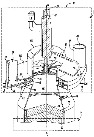
A compact fuel processor was designed by Ahmed et al., 2009 [39] based on the ACR concept. The advantage of this fuel processor over that designed by Kumar et al., 2005 [37] is its compact nature where most of the steps are included in one housing. A cross-sectional
view of a fuel processor is shown in Figure 16. The fuel processor (10) is comprised of an
exterior housing (20), inner reforming zone (30), an outer reforming zone (40), a cooling
zone (50), a sulfur removal zone (60), and a WGS zone (70). It also includes a steam heating
zone (80), an air heating zone (90), and an ignition source (100). The catalyst zone is loaded
with a PO catalyst and a SR catalyst or a catalyst that can catalyze both PO and SR reactions.
PO and SR are performed in the inner reforming zone. A sulfur removal material
effective in removal of compounds like H2S or COS, from the reformate gas stream is
provided in sulfur removal zone (60). Two zones for WGS reaction are provided with two
different catalysts. Zone 1 contains Gd-CeO2 or platinum on CeO2 supported on aluminum
based catalyst, while second WGS zone (480) comprises of CuZnO based WGS catalyst. A
top cover plate encloses the fuel processor (510) and is secured with bolts (520) with a
graphite based gasket (540).
Pipes (530) are provided for supplying sulfur containing fuel to the removal zone
(460). Inlet pipe allows the heated steam and fuel to enter mixing nozzle (436), the mixer is
supplied with air before entering inner reforming zone (430). This pipe is inserted through
the insulation (545). The top plate (510) also includes steam outlet pipe (570) which allows
steam to flow out fuel processor (410) into pipe (580) to juncture (590) where it mixes with
fuel and enters pipe (595) prior to entering pipe (560).
A bottom plate (600) is provided to close the fuel processor (410). The plate is
provided with a perforated outer portion (602) below second WGS zone (480) and is secured
with bolts (610) to lower exterior section (612). The plate provides an exit for the reformate
gas from the fuel processor (410). It flows through the perforations from outer portion (602) and enter into lower exterior section (612). The reformate gas from lower exterior section
28 Air enters through the inlet (650) and is heated as it passes through coils (660) in outer reforming zone (440) before reaching air pipe (435) where it is further heated before entering mixing nozzle (436). Steam or water enters through steam inlet (670) and then
passes through steam coils (680) where it used to cool the reformate gas in the zones (450),
(460), and (470). Theproduced heated steam flows out through the steam outlet pipe (570).
Similarly fuel enters fuel inlet (690) and circulates through fuel heating coils (695)
around the exterior of exterior housing (420) before exiting fuel outlet (700). The heated fuel
enters fuel pipe (710) before reaching juncture (590) where it is combined with heatedsteam.
A further cooling of second WGS zone (480) is accomplished by supplying cooling
water into secondary water inlet (720), which then circulates through secondary water coils
(725) before exiting secondary water outlet (730). This allows the temperatures of second
WGS zone (480) to be maintained at a differenttemperature from first WGS zone (470) since
[image:29.612.133.510.262.506.2]different catalyst are used inboth the zones.
29 Figure 16: Fuel processor designed by Ahmed et al., 2009 [39].
2.3
Reformers start up:One of the major areas of developments in an ATR technology is start up of the reformer. The start up of the reformer is very crucial for an ATR reformer since it needs to have short start up period giving the user better control over the system. The transition period of a cold reactor to the operating temperature is a key factor, as it requires synchronization with the rest of the fuel processing processes and close control over the reaction parameters.
The start up of ATR reformer is performed by initiating PO reaction over the catalyst bed, by reacting fuel and the oxidant and making use of the exothermic heat to increase the temperature of it, the reaction is switched to the ATR mode by introducing steam. The main aim of these investigations is to reduce the start up time.
Yukihiro and Mizuno,2009 [40] used pre heating means placed upstream of the ATR catalyst to preheat the catalyst to the desired temperature. Figure 17 shows an ATR start up method developed by Yukihiro and Mizuno, 2009 [40].
30 The shift from the first preheating step to the second preheating step is achieved at 250oC or higher temperature, while the shift from the second preheating step to the steady state ATR is performed with catalyst bed temperature reaching at 600°C.
In the invention the first preheating step is achieved by means of burner, by introducing the vaporized liquid and air into the burner and igniting them. The air-fuel ratio prefferd is in the range of 1 to 2 (volume ratio). In the second preheating step the burner is turned OFF and combustion is allowed to take place over the catalyst. The burner operation is stopped by increasing the air flowrate to extinguish the burner flame. By use of catalytic combustion the catalyst bed outlet temperature is raised to sufficient value without the catalyst bed inlet alone being heated. The preferable air-fuel ratio in the second preheating step is in the range of 2.5 to 5 (volume ratio).
[image:31.612.156.475.291.529.2]After the second preheating step, steam is fed to the preheated reforming catalyst; the amount of liquid fuel fed is varied in the predetermined amount to achieve a steady state ATR reaction.
Figure 17: ATR reformer start up developed by Yukihiro and Mizuno, 2009 [40]
Arcuri et al., 2008 [41] devised an ignition free approach for ATR reformer start up. The invention describes a flameless method using a feed composition which is outside of the flammability envelop to allow the catalyst to initiate the PO reaction without the risk of introducing a flammable mixture to process volumes downstream of the ATR reformer.
In the inventive process, a gas mixture comprising of about 5 to 10 % steam, 20 to 30
% natural gas and about 2 % H2 of natural gas flow (or less than about 0.6% of the total flow)
31 steam/NG ratio well above the upper flammability limit is introduced to the reformer. Upon introduction of these non-flammable mixtures, the onset of pre-reforming can be observed through a decrease in the catalyst bed and downstream process temperatures or analysis of gas composition. According to the invention a relatively very high gas flow rates having Reynolds number flow, >about 100,000, is employed. According to the invention the gas velocity should be sufficient to ensure that the feed gas residence time prior to contacting the catalyst is less than the time required for auto-ignition i.e. the feed gas should reach the ATR catalyst prior to the onset of auto-ignition. According to the method the catalyst employed in the processes should possess high activity for PO. The steam content of the mixture can also be varied to avoid any soot formation over the catalyst.
Likewise another flameless method was devised by Wheat et al., 2006 [42] who introduced an oxidizer before the ATR reformer for start up of the reformer. According to the inventors the process involves bringing the oxidizer to the operating conditions by lighting off the oxidizer and the ATR reformer. The oxidizer light off involves a reaction of fuel and air over the catalyst in a desired temperature range. Similarly, the ATR the light off is considered when the catalyzed reaction occurs between the process stream and a stream received from the oxidizer. Few different methods of stat up, for both the oxidizer and ATR reformer were reported. In one such method the oxidizer is purged with air at an initial temperature to generate a part of the heat, by producing ignition heat in at least one portion of the purged oxidizer. This achieved by heating a portion of a catalyst bed to least light off temperature or actuating a spark source. The ignition heat in the catalyst bed is generated by heating it to 280° C by use of heat exchangers. Fuel is then introduced to the heated region of the oxidizer reactor in such a way that fuel and air mixture stays below the lower explosive limit of the fuel, followed by heating the oxidizer to the operating temperature. The operating temperature is high enough to start and sustain a catalyst reaction of the fuel air mixture. The oxidizer temperature is maintained between ~400°C and 800°C showing that the oxidizer is lighted off.
Similarly for the ATR reformer light off begins with purging the reformer with fuel to the upper explosive limit of the fuel. In the invention a non-pyrophoric shift catalyst is placed after the reformer. The light off continuous by maintaining the WGS catalyst at a temperature between approximately 150° C and 200° C, sufficient to prevent condensation of water therein. The purged ATR reformer is then heated to the light off temperature of the WGS catalyst with fuel flowing through the reformer. Finally air is introduced to produce an air and fuel mixture and heating the reformer to 600 to 900°C, and maintaining the non-pyrophoric shift catalyst to approximately 250°C.
A different approach was examined by Pettit et al., 2007 [43] where they devised an separate chamber in the ATR reformer for startup purposes. Figure 18 shows a schematic of the reformer designed by Pettit et al., 2007 [35].
According to the invention a multi port ATR reformer (10) was developed with fuel
inlet system (12), a start-up system (16) and a normal operation system (18), both in fluid
contact with the common volume (22). A start-up air inlet (24) and a fuel inlet (20), makes
up as a part of start-up system (16). The start-up air inlet (24) includes a port (25) embedded
in housing (510), which is in fluid contact with an annular volume (26). This port is also in
32 placed within the annular volume (26), radially inward from port (25), and is in further
contact with a swirler or vanes (30) which are symmetric with respect to centerline.
Air passes from the porous material (28) and then into the swirler (30). Swirler (30) is
further connected to the common volume (22) and is utilized to induce a desired flat
tangential air velocity profile before it enters the volume (22). The common volume (22) is
used for both the mixing volume for normal operation and the site for thermal combustion during start-up operation.
Common volume (22) is placed in a conical housing positioned upstream from the
reforming section (14). The common volume is provided with an ignition source (32), heat
shield (50), and a temperature sensor (34). The heat shield provides a boundary between the
common volume (22) and the reforming section (16). The temperature sensor (34) is a
thermocouple mounted on the heat shield (50).
The fuel inlet (20) introduces metered fuel into the start-up system (16),via metering
device (21) embedded in the housing (500), allowing the housing to be in contact with the
common volume (22). Air and the introduced fuel form a mixture is ignited using the ignition
source (32).Once the light off temperature in the reforming section (14) is achieved sensed
33
Figure 18: Schematic of the ATR reformer designed by Pettit et al., 2007 [43].
[image:34.612.162.477.58.515.2]Unlike the previous inventions, Yanlong and Zhao, 2005 [44] developed a catalytic method for start up of an ATR reformer. A schematic of the ATR reformer is shown in
Figure 19. Two catalyst portions are placed in the reformer one in the upstream side (14) and
one on the downstream portion (16) enclosed in a common housing (18). The upstream
catalyst (14) has a comparatively low light-off temperature, while the downstream catalyst
![Figure 1: Catalyst configuration comprised of housings (A) and the structure (B) patented by Ahmed et al., 2010 [23]](https://thumb-us.123doks.com/thumbv2/123dok_us/7981928.202732/8.792.98.621.82.382/figure-catalyst-configuration-comprised-housings-structure-patented-ahmed.webp)
![Figure 4: A schematic of ATR reformer designed by Docter et al [28]. In the figure, 1 and 3 represent the catalyst structure in the reaction zone 1 with the inlet and outlet zones shown by 7 and 8 and external heater 6](https://thumb-us.123doks.com/thumbv2/123dok_us/7981928.202732/12.612.112.500.78.297/schematic-reformer-designed-represent-catalyst-structure-reaction-external.webp)
![Figure 5: Configurations of ATR reformer with external heat source designed by Doctor et al., 2009 [28]](https://thumb-us.123doks.com/thumbv2/123dok_us/7981928.202732/15.792.101.547.46.484/figure-configurations-atr-reformer-external-source-designed-doctor.webp)
![Figure 10: An autothermal SR reformer designed by Retallick et al., 2007 [33].](https://thumb-us.123doks.com/thumbv2/123dok_us/7981928.202732/20.612.118.521.46.211/figure-autothermal-sr-reformer-designed-retallick-et-al.webp)
![Figure 12: An autothermal SR process invented by Fillipi at al., 2008 [34].](https://thumb-us.123doks.com/thumbv2/123dok_us/7981928.202732/22.612.138.498.247.576/figure-autothermal-sr-process-invented-fillipi-al.webp)
![Figure 13: Fuel processor designed by Pettit et al., 2007 [35].](https://thumb-us.123doks.com/thumbv2/123dok_us/7981928.202732/24.612.112.550.225.494/figure-fuel-processor-designed-pettit-et-al.webp)
![Figure 14 shows a reformer heat exchanger arrangement based fuel processor designed by Malhothra and Gosnell, 2009 [36]](https://thumb-us.123doks.com/thumbv2/123dok_us/7981928.202732/26.612.142.474.187.479/figure-reformer-exchanger-arrangement-processor-designed-malhothra-gosnell.webp)
![Figure 15: Fuel processor designed by Kumar et al., 2005 [37].](https://thumb-us.123doks.com/thumbv2/123dok_us/7981928.202732/29.612.133.510.262.506/figure-fuel-processor-designed-kumar-et-al.webp)
![Figure 17: ATR reformer start up developed by Yukihiro and Mizuno, 2009 [40]](https://thumb-us.123doks.com/thumbv2/123dok_us/7981928.202732/31.612.156.475.291.529/figure-atr-reformer-start-developed-yukihiro-mizuno.webp)