Iterative Learning Control as an
Intervention Aid to Stroke
Rehabilitation
C. T. Freeman 1, A. -M. Hughes2, J. H. Burridge2, P. H. Chappell1, P. L. Lewin1, E. Rogers1
1 School of Electronics and Computer Science
2 School of Health Professions and Rehabilitation Sciences,
University of Southampton, UK. contact author E. Rogers [email protected]
1
Introduction
Incidence of stroke in the UK is approximately 100,000 new cases each year. One third of patients will not survive the first year and another third will make a full recovery. Half of all acute stroke patients startingrehabilitation will have a marked impairment of function of one arm of whom only about 14% will regain useful sensory-motor function [1, 2]. It has been argued that arm and hand function is more important than mobility in achievingindependence followingstroke [2]. The concept of ‘learned disuse’ is thought to be a significant barrier to recovery of sensory-motor function. Unim-paired individuals learn new skills though practice, with feedback in various forms, for example visual or proprioceptive [3]. The problem facingthe stroke patient is that they are unable to practice because of impaired motor control. As a consequence of the inevitable disuse, neuroplastic changes within the motor cortex areas previously responsible for control of the paralysed limb form new connections with local areas that retain voluntary control [4]. Consequently, delay in recovery may lead to a decreased likelihood of recovery occurring.
Functional electrical stimulation (FES) can provide the experience for the patient of movingand consequently may limit the problem of learnt disuse and has been used with some success to im-prove recovery of upper limb motor control [5]. Recent studies have shown that when stimulation is associated with a voluntary attempt to move the limb, improvement is enhanced [5, 6]. Triggering of stimulation through voluntary activity, using sensory information such as the electromyographic (EMG) activity of the same muscle, joint position or acceleration, has been demonstrated, but these techniques do not allow feedback that could be used to adjust stimulation parameters and thus provide more precise stimulation.
This paper describes the experimental test facility that has been designed as part of a current project whose aim is to investigate the use of iterative learning control (ILC) and related strategies to mediate the electrical stimulation applied to a number of muscles of the shoulder and upper limb of stroke patients. ILC is a technique that has its origins in the area of industrial robotics and is especially targeted at systems operating in a repetitive mode with the additional requirement that a specified output trajectory over a finite interval (or trial) is followed to a specified level of precision. Moti-vated by human learning, the basic idea of ILC is to use information from previous executions of the task in order to improve performance from trial to trial. In the context of this work, ILC offers the opportunity of allowingthe user to learn how to perfect a given task by controllingthe amount of additional stimulation applied from one trial to the next. If this has been achieved, then further refinement is possible to reduce the stimulation effort supplied by the control scheme and thereby increase the effort necessary from the subject. In particular, ILC requires a basic representation of the underlying(dynamic) relationship between stimulation (or input) and response (or output) and also
the specification of a target (or reference) trajectory to form the goal for the ILC scheme to achieve. The representation can be in a variety of forms such as a set of (nonlinear) mathematical equations or in the shape of linear function approximations based on experimental measurements. In the present case, the model of the patient consists of inputs in the form of variables characterisingthe applied FES signals and outputs comprisingvariables which encompass the patient’s resultingdynamics. This will then be used to design ILC algorithms which will generate a sequence of stimulation signals to greatly improve the patient’s trackingof the trajectory over the course of number of trials, where this can also be a variable in the design procedure. It is then possible to include a switching strategy whereby the learningcontrol is activated/deactivated with the controller at such instances ‘frozen in place’. This will allow the patient’s performance duringan experimental sequence to be included, i.e stimulation will be applied in accordance with a set of rules;
1. If the subject performs the movement without error no stimulation is applied and after a given number of successful performances the task is made more difficult.
2. If the subject fails to perform the desired movement, stimulation will be applied on the next attempt based on the type and degree of error.
3. If the stimulation pattern results in a satisfactory performance the same stimulation will continue to be applied and, after a certain number of repetitions, either reduced or the task made more difficult.
In order to use ILC in the way described, a blend of data acquisition, algorithm development and subject-based experimentation is required. The method necessitates the activation of several muscles controllingarm and shoulder movement and the use of a variety of sensors to record joint positions, velocities, accelerations, forces and torques.
2
Experimental Design
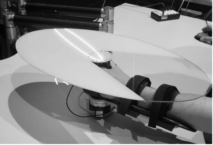
A maximum of four muscles will initially be selected for stimulation and the trackingtask will consist of reachingmovements with the subject seated. In order to simplify the controller design and display the trajectory with maximum clarity, only trajectories in a fixed horizontal plane will be used and the patient’s forearm will be constrained to move in this plane by a robot that is designed specifically for this purpose. Initial tests have shown that subjects are able to perform trackingtasks with greater accuracy when they are able to see the required trajectory at the same time as the present location of their own arm, and, furthermore, when they can observe the future path that the trajectory will take. In order to facilitate this, the trajectory will be displayed usinga projector mounted above the subject which will show the entire trajectory path as well as a movingspot to indicate the desired current position of a point immediately above the subject’s hand. A target will be mounted on the robot in the horizontal plane passingthrough this point to allow the trajectory to be clearly seen by the subject as they perform the trackingtask. A cross-hair and a number of concentric rings will be drawn on the target to emphasise the point that is supposed to follow the moving spot as it progresses alongthe trajectory.
constructed. The workspace area has been chosen to permit the subject to perform full arm reaches in a horizontal plane whose height can be adjusted easily between tests. A view of the trajectory
Figure 1: Complete experimental system
displayed on the target above the subject’s arm is shown in Figure 2 which also shows the restraint used to strap the subject’s forearm to the most extreme link of the robot.
2.1 Robotic System
The robotic workstation has been designed and manufactured at the University of Southampton and consists of a five-bar linkage mechanism which constrains the subject’s arm to lie in a horizontal plane that can be adjusted between experiments. The arm is primarily constructed out of carbon fibre to increase the strength/weight ratio, and uses two DC brushless motors due to their high torque and acceleration capabilities. The robot incorporates encoders to measure the required joint angles and a six axis force/torque sensor to measure the forces and torques applied by the subject.
Figure 2: Arm restraint and trajectory display
arm is restrained, will be incorporated into the model of the human subject, so that it is possible to set m3=I3 = 0. In order to satisfy the orientation constraints, it is also necessary to set
ϑ2 =ϑ4−ϑ1
ϑ5 =ϑ1−ϑ4 (1)
and the vector of joint variables can be chosen as
q= [ϑ1ϑ4]T (2)
The joint space dynamic model can then be expressed in the form
B(q) ¨q+C(q,q˙) ˙q+Fvq˙+Fssgn( ˙q) +Fe(q) =τ−JT(q)h (3) in which h= [Fx Fy Fz]T denotes the vector of forces exerted by the end-effector on the environment in the Frame 0 coordinate system, J(q) is the Jacobian of the system,
B(q) =
m1l211+I1+m2(l11+l12)2+m5l512 +I5 (m5(l41+l42)l51+m2(l11+l12)l21) cos(ϑ2) (m2(l11+l12)l21+m5(l41+l42)l51) cos(ϑ2) m4l412 +I2+m5(l41+l42)2+m2l221+I4
(4)
and a possible choice for the non-uniqueC(q,q˙) matrix is g iven by
C(q,q˙) =
0 −(m5(l41+l42)l51+m2(l11+l12)l21) sin(ϑ2) ˙ϑ4
(m2(l11+l12)l21+m5(l41+l42)l51) sin(ϑ2) ˙ϑ1 0
(5) The forms Fv = diag{Fv1, Fv2}, Fs = diag{Fs1, Fs2} and Fe(q) = diag{Fe1(q), Fe2(q)} have been assumed on the basis of experimental tests. For a description of the modellingand control of manip-ulators see, for example, [7, 8].
A global linearisation is achieved by choosing the input torque generated by the motors to be
u=B(q)y+C(q,q˙) ˙q+Fvq˙+Fssgn( ˙q) +Fe(q) +JT(q)h (6)
to produce ¨q = y. We therefore need a stabilisingcontrol law y which allows good tracking but is insensitive to disturbances. We select
y=J−1(q)KM−1
KKx˜−KBx˙ −KMJ˙(q,q˙) ˙q−h
m I1,1
m ,I2 2
m ,I5 5
m ,I4 4
l11
l12
l21
l52
l51
l41
l42
l22
y0
x0
y1
x1
y5
x5
y4
x4
h2 h4
h5 h1
y3
x2
m ,I3 3
x3
y2
h3 l31
[image:5.612.174.454.15.434.2]l32
Figure 3: Geometry of five-link robotic arm
to produce
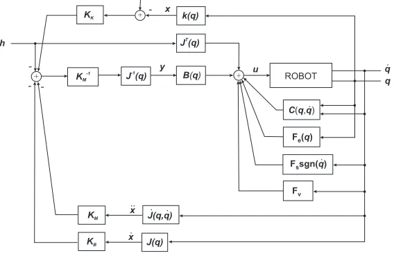
h=KKx˜−KMx¨−KBx˙ (8) where ˜x = xd−x, x = k(q), ˙x = J(q) ˙q and ¨x = J(q) ¨q + ˙J(q,q˙) ˙q. Here k(q) is the direct kinematics equation for the system, and the gain matrices have the form KK = diag{KK, KK},
KB = diag{KB, KB} and KM = diag{KM, KM} where KK, KB and KM are scalars. This control
approach is shown schematically in Figure 4 and is a form of impedance control which ensures the robot’s safe interaction with an unknown environment [9]. The terms Fe1(q) and Fe2(q) have been
identified by fittingpolynomial functions to the results of static tests conducted at a large number of points throughout the workspace. The remaining parameters have been obtained using dynamic parameter identification which exploits the property of linearity of the model. The arm is moved through a number of trajectories which are sufficiently kinematically rich to capture the necessary dynamics, and the parameters are calculated usingan optimisation procedure [10].
B q( )
C q q( , )
+ ROBOT
-y u q.
q
.
F ( )eq
Fssgn( )q.
Fv
J (q)T
+ h KB KM KM -1
KK +
xd
k(q)
J-1(q)
J(q, )q
[image:6.612.173.457.11.199.2]J(q) -. . -x . x .. x
Figure 4: Robotic control scheme
experienced by the sensor, Fs, in coordinate Frame 2 usingthe expression
Fs=
Fxs Fys Fzs Txs Tys Tzs =
1 0 0 0 0 0
0 1 0 0 0 0
0 0 1 0 0 0
0 l33 0 1 0 0
l33 0 0 0 1 0
0 0 0 0 0 0
R2 3 0
0 R23
Fxp Fyp Fzp Txp Typ Tzp (9)
in whichR23 is the rotation matrix of Frame 3 with respect to Frame 2. It is then possible to find the external forces applied in response to this by the robot in the Frame 0 coordinate system,h, using
h=
−R0
2 0
Fs (10)
whereR02 is the rotation matrix of Frame 2 with respect to Frame 0.
2.2 Periphery Systems
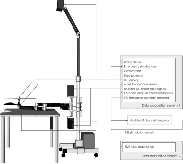
The necessary ancillary systems and supplementary issues needed to accomplish the project’s goals are described in greater detail in this section. A diagrammatic representation of the system’s signal requirements is presented in Figure 5.
2.2.1 Safety Considerations
The robot conforms to all relevant British Standards relatingto the use of medical devices in trials with human subjects. An emergency cut-off switch is positioned next to the subject’s free hand, and another is situated next to the operator. Three limit switches restrict the robot’s range of movement and the use of the control scheme described in Section 2.1 ensures its safe interaction with an effectively unknown environment. A large number of signal rate limiters, saturation constraints and filters are implemented in the control software. The current input to the amplifiers is limited which in turn limits the available torque.
2.2.2 Noise Limitation
EMG electrode signals Modified 4 channel stimulator Data projector
6 axis torque/force sensor Brushless DC motor input signals Encoders and Hall effect transducers Goniometers
FES stmulation pulewidth demand Limit switches
Emergency stop buttons
LED display
Data acquisition system 1
Data acquisition system 2
[image:7.612.136.512.18.354.2]FES stimulation signals
Figure 5: Experimental design of robot using EMG and FES
sensor’s analogoutput is typically less than 10mV makingit extremely susceptible to EMI. This has been greatly reduced by using a six channel voltage amplifier placed within the robot’s final link in combination with screeningand ferrites.
2.2.3 Goniometers
Dependingon the complexity of the underlyingmodel of the human subject that is assumed, a mini-mum of two goniometers are necessary in order to measure their kinematics to an acceptable degree. The system has the facility to include seven goniometers which will enable highly accurate models of the shoulder and upper limb to be used.
2.2.4 FES system
2.2.5 Calibration
The use of incremental encoders and the effect of sensor drift necessitates their resettingand calibration prior to each session of tests. A spring-loaded module is used to mate with the robot and ensure a reset point is accurately and repeatably met. Microswitches detect the co-location and activate the encoder and force sensor resettingwhen the subject has released the end-effector. The force/torque sensor amplification circuit is calibrated usingan automatic procedure of applyingknown voltages. The table is rigidly connected to the robot at several points in order to guarantee the synchronisation of the trajectory display in relation to the location of the robot. Display trajectories have been produced with which to accurately calibrate the orientation of the data projector.
2.2.6 Software Overview
The software is capable of recordingall the necessary patient information as well as test measurements for all the experiments to be undertaken. A user-friendly graphical user interface allows the operator to change test parameters quickly and easily, whilst powerful realtime hardware permits extremely complex control algorithms to be conducted using very high sample rates.
2.2.7 Trajectory Display
The display has been generated using software designed to minimise the latency and maximise the update rate of the display. The trajectories have been presented in a simple manner which has been chosen to maximise clarity. LEDs mounted on the end-effector change from red to amber immediately prior to the start of each test, and to green as the test commences. During the test, they are used to indicate how close the trajectory is beingfollowed. An elliptical target has been manufactured usingtwo plastics with different light transmittance properties which permits the trajectory to be clearly seen at all points on its surface, as well as allowingthe subject’s arm to be clearly visible at all times. The trajectories used will be ellipses with variable startingpoints, orientations, semiminor and semimajor axis lengths, and speed profiles.
2.2.8 EMG Recording
A separate data acquisition system will be used to record the EMG patterns of the muscles chosen for activation. This will be conducted in trials prior to the application of stimulation in order to define normal EMG activation patterns which will then be used to extract modellingparameters and produce activation trajectories that will later be used in the controller.
3
Future Work
Preliminary trials are about to commence usingthe system described. Experiments will be conducted using10 subjects, each of whom have full shoulder and arm use and are over 50 years of age. The aim of these tests is to identify and validate models of each subject’s shoulder and upper arm and to determine the effectiveness of the ILC algorithms used to control the FES during the tracking tasks. The subjects will not contribute any voluntary control to assist the movement. Followingthe conclusion of these trials, the system will then be used in larger trials using stroke patients.
4
Acknowledgements
References
[1] Royal College of Physicians. Stroke: towards better management. Royal College of Physicians, London, 1989.
[2] D. T. Wade, R. Langton-Hawer, V. A. Wood, C. E. Skilbeck, and H. M. Ismail. The hemiplegic arm after stroke: measurement and recovery.Journal of Neurology, Neurosurgery, and Psychiatry, 46(4):521–524, 1983.
[3] R. A. Schmidt and T. D. Lee.Motor control and learning: a behavioral emphasis. Human Kinetics Publishers, 3rd edition, 1998. Part 3: Motor Learning, pp. 261-285.
[4] M. Castro-Alamancos, L. Garcia-Segura, and J. Borrell. Transfer of function to a specific area of the cortex after induced recovery from brain damage. European Journal of Neuroscience, 4(9):853–863, 1992.
[5] J. H. Burridge and M. Ladouceur. Clinical and therapeutic applications of neuromuscular stim-ulation: A review of current use and speculation into future developments. Neuromodulation, 4(4):147–154, 2001.
[6] T. Sinkjaer and D. Popovic. Peripheral nerve stimulation in neurological rehabilitation. In 3rd world congress in Neurological Rehabilitation, Venice, Italy, April 2002.
[7] H. Asada and J. J. E. Slotine. Robot analysis and control. John Wiley & Sons Inc, 1986.
[8] L. Sciavicco and B. Siciliano. Modelling and control of robot manipulators. Springer-Verlag UK, 2001.
[9] J. E. Colgate and N. Hogan. Robust control of dynamically interacting systems. International Journal of Control, 48(1):65–88, 1988.