sciences
Article
A Neural Network Based Landing Method for
an Unmanned Aerial Vehicle with Soft Landing Gears
Cai Luo1,* , Weikang Zhao1, Zhenpeng Du2and Leijian Yu3
1 College of Mechanical and Electronic Engineering, China University of Petroleum (East China), Qingdao
266580, China
2 School of Petroleum Engineering, China University of Petroleum (East China), Qingdao 266580, China
3 Department of Design, Manufacture & Engineering Management, University of Strathclyde,
Glasgow G1 1XJ, UK
* Correspondence: luo_cai@upc.edu.cn
Received: 27 June 2019; Accepted: 22 July 2019; Published: 25 July 2019
Abstract:This paper presents the design, implementation, and testing of a soft landing gear together with a neural network-based control method for replicating avian landing behavior on non-flat surfaces. With full consideration of unmanned aerial vehicles and landing gear requirements, a quadrotor helicopter, comprised of one flying unit and one landing assistance unit, is employed. Considering the touchdown speed and posture, a novel design of a soft mechanism for non-flat surfaces is proposed, in order to absorb the remaining landing impact. The framework of the control strategy is designed based on a derived dynamic model. A neural network-based backstepping controller is applied to achieve the desired trajectory. The simulation and outdoor testing results attest to the effectiveness and reliability of the proposed control method.
Keywords:unmanned aerial vehicle; neural network; soft landing gear
1. Introduction
Unmanned aerial vehicles (UAVs) in human-unreachable environments have aroused great interest in the civil, military, and engineering fields [1–3]. Within the group of drones, quadrotor helicopters have gained increasing interest, due to their maneuverability, simple structure, affordability, and agility. Information about the use of UAVs can be obtained from a number of new publications, with topics ranging from earthquake searching to the deployment of air-dropped goods for humanitarian purposes [4–6]. Furthermore, for missions such as delivering first-aid supplies, drones always need ground support, such as airports or landing stations. However, outside cities and bases, UAVs may quite easily encounter the situation that there is no suitable landing assistance infrastructure nearby [7–9]. This will severely limit the usability of drones.
Flying animals, such as birds, can perch on trees, poles, and other non-flat surfaces which are not suitable for UAV landing. Equipped with this soft landing ability, birds may occupy a high vantage point [10]. They can stay there to search, forage, and rest for an extended period of time [11,12]. As a high-challenge landing approach, perching refers to precise landing pose control and the effectiveness of energy absorption [13]. Cory and Tedrake, of the MIT Computer Science and Artificial Intelligence Laboratory, have analyzed and presented fixed-wing precise drone landing tests and demonstrated that angles of attack are critical factors during the touchdown procedure [14]. Mirko Kovac from the Imperial College of London designed an aerial robot equipped with soft shock absorbers which can land on a convex surface with diameter longer than robot’s body length [15]. Subsequently, many inspired mechanical devices have been investigated to test this hypothesis. For example, a pitch-up touchdown sequence, consisting of distance detection, UAV nose up, and soft
contact with a landing zone, has been proposed by Stanford University [16,17]. A passive micro-spine grapple was proposed for perching under tree branches [18].
UAVs are, at present, continue to be sent out to achieve safety, security, and rescue missions. Numerous robust control schemes have been developed to address the control problems in quadrotor helicopters associated with uncertainties and delays. In [19], a dynamic model of a quadrotor helicopter with a suspended payload was established, and a non-linear controller, without considering the parametric uncertainty, was also presented. In [20], a switching model predictive controller was proposed for the rejection of external disturbances. In [21], the author presented a feedback linearization control approach by considering the disturbance from the payload. To maintain the posture tracking performance against external uncertainties, an H∞ theory-based approach was proposed in [22]. As an alternative method, the sliding model control technique was used in [23] to reduce the parameter variation effect on the closed-loop control system. In addition, a quadrotor transportation platform involves time-varying delays. In [24], constant state delays were analyzed within the quadrotor helicopter system. The input delays to the system were further discussed in [25]. In [26–28], radial basis function neural network (RBFNN)-based PID controllers were proposed to control quadrotor flying robots without separating the inner loop and the outer loop. However, the multiple non-linear uncertainties and disturbances were not considered in the design approach, which has a sub-optimal impact on the performance of UAVs.
With the demand to land on a non-flat surface, this paper demonstrates the design and fabrication of a novel quadrotor helicopter system. The proposed platform uses a backstepping theory-based flight controller working with a neural network algorithm, which enables a drone to safely land on a non-flat platform. In this paper, a non-linear flight controller is proposed. First, a RBFNN approach is employed, in order to address the unknown disturbances. Second, the disturbances in the position and pose control input are suppressed with the modified neural network-based methodology. Third, the stability of the proposed control approach is proven through Lyapunov stability analysis. Finally, the RBFNN-based nonlinear controller is verified by real-time outdoor experiments.
The main three contributions of this paper are as follows:
• The design of a novel elastomer landing gear is achieved. It guarantees safe landing on a convex surface with diameter smaller than the quadrotor body length through a conventional vertical landing strategy.
• A neural network-based backstepping technique is adopted to meet the desired vertical landing requirement, and soft landing is achieved using the proposed controller with near-zero landing speed. The stability of the landing control system is proved through the Lyapunov approach and the backstepping technique.
• The proposed platform is challenged in a real flight outdoor scene, which validates the controller’s effectiveness and robustness.
This paper is organized as follows. Section2introduces the modeling of the UAV and soft elastomer landing gear. In Section3, we introduce the landing control algorithm and stability analysis. The simulation of the quadrotor helicopter landing is discussed in Section4. The prototype of the UAV and real-world outdoor setup used to assess the control method are demonstrated in Section5. Finally, the conclusion and future work are discussed in Section6.
2. Quadrotor Modeling and Landing Gear Architecture
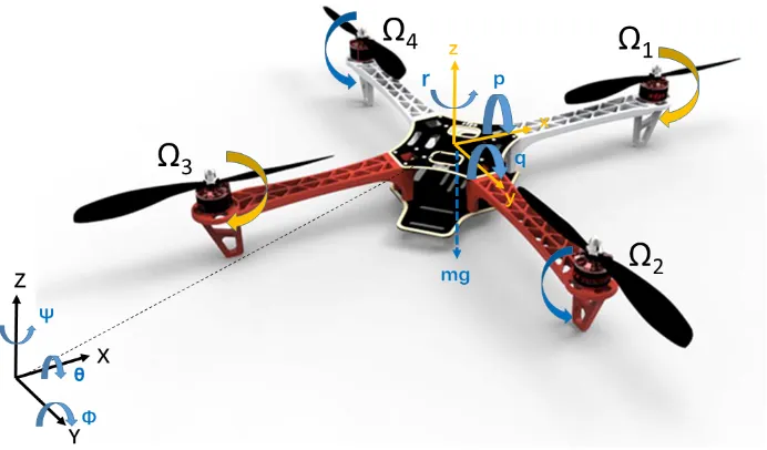
Figure 1.A cross-type quadrotor helicopter.
2.1. The Modeling of the Quadrotor Helicopter
According to the formalism of Newton–Euler approach, the quadrotor dynamics can be expressed as [32]:
¨
x= (cosφsinθcosψ+sinφsinψ)u1 m +Dx ¨
y= (cosφsinθsinψ−sinφcosψ)u1 m +Dy ¨
z= (cosφcosθ)u1
m −g+Dz ¨
φ=θ˙ψ˙Iy
−Iz
Ix
+ Jr Ix
˙
θΩr+ l
Ix
u2+Dφ
¨
θ=ψ˙φ˙Iz−Ix Iy
− Jr Iy
˙
φΩr+ l
Iyu3
+Dθ
¨
ψ=φ˙θ˙Ix
−Iy
Iz
+ 1 Izu4
+Dψ,
(1)
where(x,y,z)is the position of the center of the gravity of the UAV in the earth-frame;(p,q,r)denotes the angular velocity in the body-frame;mis the total mass of the UAV;gis the gravity acceleration;l represents the arm length of UAV; the moments of inertia are represented byIx,Iy, andIz, respectively;
φ,θ, andψare the roll, pitch, and yaw Euler angles; Jr denotes the moment of inertia;Dx,Dy,Dz,
Dφ,Dθ, andDψrepresent the uncertain disturbances;Ωi(i=1, 2, 3, 4)is theith propeller speed; and
Ωr=Ω1−Ω2+Ω3−Ω4is the overall speed of propellers.
2.2. The 3D Schematic and Modeling of the Soft Landing Gear
As presented in Figure2, a soft passive gear is fixed under the quadrotor helicopter to facilitate landing impact absorption. The requirements for this end-effector include:
• The ideal touchdown velocities and posture of the quadrotor helicopter.
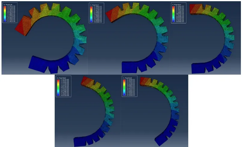
• Suitable mechanical and material properties of the landing gear to absorb the high-speed impact force to protect the body of the UAV, as seen in Figure3.
Figure 2.The 3D schematic of the proposed quadrotor helicopter.
The Elastosil M4601 silicone material that was used to fabricate the soft landing gear has hyper-elastic properties. The ABAQUS package was used to simulate the impact displacement and the reactions of the soft landing gear. In the simulation, the coefficients of strain energy were set as C10 = 0.11 and C20 = 0.02. The density was set as 1130 kg/m3.
The coordination system of the landing gear is shown in Figure4. In the simulation, the upper part of the gear was allowed to move in thex–zplane, while the lower part was allowed to rotate around thex-axis. The impact load was added to the upper part of the gear along thez-axis. Figure3 demonstrates the maximum displacement of the soft landing region when encountering different impact forces (5 N, 10 N, 15 N, 20 N, and 25 N).
[image:4.595.96.500.372.617.2]Figure 4.The proposed soft landing gear.
3. Controller Design and Stability Analysis
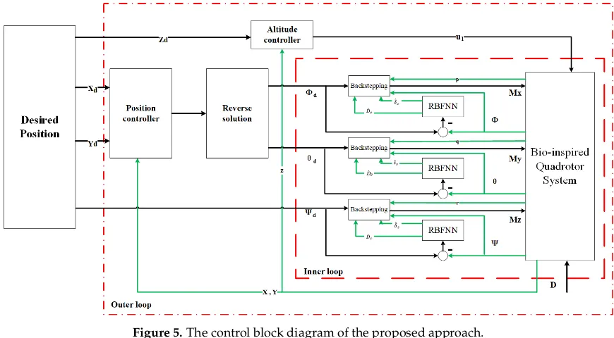
As shown in Figure5, the control system of the proposed quadrotor contains two loops: An outer loop and an inner loop. The PID control method in the outer loop is used for the position and altitude control, while the exploited RBFNN-based control approach is implemented in the inner loop for stable attitude control.
Figure 5.The control block diagram of the proposed approach.
3.1. PID Position and Altitude Control Design
Pzis the PID controller of UAV altitude in thezdirection, which is defined as
Pz=KzP(zd−z) +KzI k
∑
i=1
ts×(zdi−zi) +KzD(z˙d−z˙), (2)
whereKzP,KzI, andKzDare the proportional, integral, and differential coefficients in the controller,
[image:5.595.79.514.372.612.2]PxandPyare the PID controller of the UAV position in the x–y plane, which are defined as
Px=KxP(xd−x) +Kxl∑ki=1ts×(xdi−xi) +KxD(x˙d−x˙)
Py=KyP(yd−y) +KyI∑ki=1ts×(ydi−yi) +KyD(y˙d−y˙).
(3)
The desired attitude angles (roll and pitch) can be derived as
φd=−arctan
P
y
Pz+g−Dx
,
θd=arctan
Px
Pz+g−Dx
. (4)
3.2. RBFNN-Based Backstepping Attitude Control Design
Attitude control using the adaptive RBFNN-based backstepping control method is shown in inner loop of Figure5. The attitude control of the quadrotor helicopter is controlled by three different inputs (roll, pitch, and yaw). The attitude control in roll, pitch, and yaw have the same design procedure in the proposed control method. For the sake of simplicity, we only take the roll channel as the example design process to describe in this section.
The roll channel is denoted as
˙ x1=x2
˙
x2= MIxx +Dθ,
(5)
wherex1is the roll angle andx2denotes the derivation ofx1.
The external disturbance is denoted, byDθ, as
Dθ=Ξx+vx, (6)
whereΞx=∆Mx/(Ix+∆Ix)denotes the external bounded disturbance andvx=−∆IxMx/[Ix(Ix+
∆Ix)]is treated as the model uncertainty.
The tracking error of roll angle is defined as [33]
e1=x1d−x1, (7)
wherex1dis the desired roll angle.
Then, the derivative ofe1is
˙
e1=x˙1d−x2. (8)
The first Lyapunov function is chosen as
V1= e21
2. (9)
The tracking error of roll angle velocity is defined as
e2=x2−x˙1d−c1, (10)
where the stabilizing functionc1is defined as
c1=αe1, (11)
whereαis a positive constant.
Thus, the derivative ofV1can be obtained by
˙
Then, the derivative ofe2can be represented as
˙
e2=x˙2−x¨1d−αe˙1=
Mx
Ix +Dθ−x¨1d+α(e2+αe2).
(13)
The assosicate Lyapunov function is denoted as
V2=V1+
1 2s
2, (14)
and the related sliding surface is designed as
s=ke1+e2, (15)
wherekis a positive constant.
The derivation ofV2can be obtained by
˙
V2=V˙1+ss˙
=−e1e2−αe21+s(ke˙1+e˙2)
=−e1e2−αe21+s
(k−α)e˙1+ Mx Ix
+Dθ−x¨1d
.
(16)
3.3. RBFNN-Based Observer
In real-world outdoor applications, the bound for the uncertaintyDθin the roll channel is hard to estimate. Considering this, we chose an adaptive RBFNN observer to adapt the estimated the uncertainty value ˆDθin the UAV system. The chosen RBFNN was a three-layer feed-forward neural
network [34,35].
The vector in the input layer isZ= [e1, ˙e1]T. By using the weighted sum method, the output is
derived as follows
ˆ Dθ=∑
N
j=1Wjφj(Z), j=1, 2,· · ·,N
φj(Z) =exp(−k
Z−Mjk2
σj2 )
, (17)
whereWjdenotes the connective weight,Nis the number of hidden nodes,Mjis the centre vector, and
the positive scalarσjdenotes the spread width. The receptive field function uses a Gaussian function
in our designed neural network.
3.4. Stability Analysis
The minimum reconstructed errorσxis defined in the roll channel as
σx=Dθ−Dˆθ(W
∗
), (18)
whereW∗represents an optimal weight vector in the approximation. Then, an associated Lyapunov function is chosen as
V3=V2+ζ1
2 (W
∗−W)T(W∗−W) +ζ2
2 δx−δˆx
2
, (19)
whereζ1andζ2are defined as positive constants, and ˆδxdenotes the approximated value of the
minimum reconstructed error;δxis provided to compensate the observed error induced by the RBFNN
Then, the derivation of the Lyapunov functionV3is obtained as
˙
V3=V˙2−ζ1(W∗−W)TW˙ −ζ2 δx−δˆxδ˙ˆx=
−e1e2−αe21+s
(k−α)e˙1+ Mx
Ix
+Dθ−x¨1d
−
ζ1(W∗−W)TW˙ −ζ2 δx−δˆxδ˙ˆx.
(20)
Following the backstepping control law [36],Uxis equal toMx, as
Ux=Mx =Ix[−(k−α)e˙1+x¨1d−γs−hsgn(s)−UH−UR], (21)
whereγandhdenote positive constants, andUHandURare designed as the robust and compensated
controllers, respectively. They are denoted as shown in Equation (22)
UH=Dˆx(W),
UR=δˆx.
(22)
The derivation ofV3is obtained as
˙
V3=−e1e2−αe21−γs2−h|s|+sDθ−Dˆθ(W∗)−δˆx−
ζ2 δx−δˆxδˆˆx+sDˆθ(W
∗)−Dˆ
θ(W)
−ζ1(W∗−W)TW˙ .
(23)
Then, ˙V3can be rewritten as
˙
V3=−e1e2−αe12−γs2−h|s|
=−zTΛz−h|s|, (24)
wherez= [e1 e2]and the symmetric matrixΛis in the form
Λ= "
α+γk2 γk+12 γk+12 γ
#
. (25)
The adaptation laws for ˙Wand ˙ˆδxare designed as
˙
W = s
ζ1φ(Z),
˙ˆ
δx= ζs2.
(26)
According to Barbalat’s lemma [37], it is noted that, when ˙V3 ≤ 0,Λis guaranteed to be positive
definite, as expressed by
|Λ|=γ(α−k)−1
4 >0. (27)
Thereby, the roll state of the quadrotor UAV is asymptotically stable, based on the aforementioned condition. The other channels (pitch and yaw) control follow the same procedure, and are not described for the purpose of simplicity.
4. Simulation
Figure 6.Quadrotor successfully landed on convex surfaces with the support of the proposed soft landing gear.
To validate the real-time performance of the controller and assess the reliability and robustness of the proposed RBFNN-based backstepping control approach in the challenge of external disturbances, a Hardware-in-the-Loop (HITL) environment was developed for the UAV. The simulation platform was made up of two main parts: A hardware part and a software part. The hardware part was the Pixhawk autopilot unit, which was used in the field tests. The software part was the Matlab aerospace simulation environment. The hardware and software parts were connected by USB/UART to send and receive flight data. The RBFNN-based control approach was implemented by MATLAB 2018b and PX4 Autopilots Support from Embedded Coder.
The quadrotor helicopter model was used, for simulation validation, with the physical parameters listed in Table1. The disturbances were added to the model byΞ=0.3 cos(0.2t)through an individual
plugin. The RBFNN in the simulation used 2, 5, and 1 neuron(s) in the input, hidden, and output layers, respectively. The centre and width in Equation (17) were chosen asm =2 andσ = 6, respectively.
The coefficientsζ1andζ2were chosen as 0.1 and 0.3, respectively. The parameters in Equation (25)
[image:9.595.183.412.548.636.2]were tuned by trial and error to achieve satisfying control performance, as shown in Table2.
Table 1.Parameters of the quadrotor helicopter.
Symbol Description Value Units
m Mass 2 kg
l Body length 450 mm
r Rotor radius 100 mm
Ix Moment of Inertia 1.85 10−3kg·m2 Iy Moment of Inertia 1.85 10−3kg·m2 Iz Moment of I nertia 2.98 10−3kg·m2
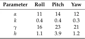
Table 2.Parameters of the backstepping sliding-mode control.
Parameter Roll Pitch Yaw
α 11 14 12
k 0.4 0.4 0.3
γ 16 23 21
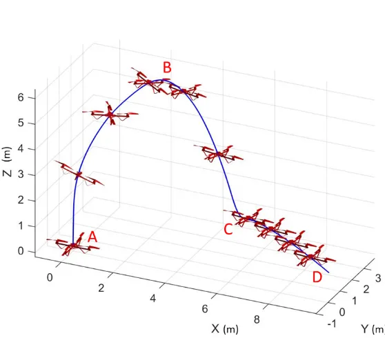
[image:9.595.226.370.669.735.2]Five simulation tests were carried out to investigate the accuracy and repeatability of the proposed method, and the simulation path can be seen in Figure7. The simulation steps were as follows:
1. The quadrotor started from an initial positionA(0, 0, 0).
2. The quadrotor flew to the positionB(2, 2, 6)and hovered there for attitude control tests; these results can be seen in Figure8.
3. The quadrotor descended to the positionC(4, 2, 2)with a speed between 5–8 m/s.
4. The quadrotor, then, received the landing positionD(6, 2, 0). The UAV began to adjust its altitude, attitude, and velocity for the landing tests.
5. The quadrotor landed on the target without a high-speed impact.
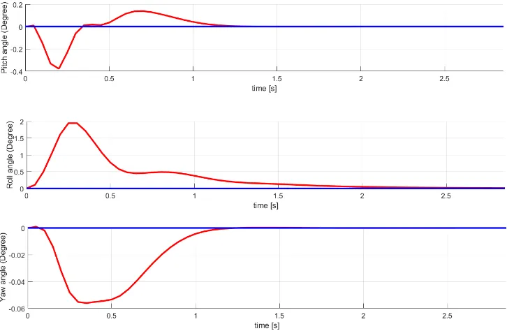
[image:10.595.183.410.312.361.2]In these tests, the numerical simulation demonstrates that all the quadrotor attitude states had a small steady-state error, subject to the external disturbance. As shown in Figure8and Table3, the steady-state error was thoroughly eliminated in a short time using the RBFNN-based backstepping control method.
Table 3.Setting time and steady-state error in the hovering tests.
Attitude Setting Time (s) Steady-State Error (Degree)
Pitch 1.1 0
Roll 2.0 0
Yaw 1.1 0
[image:10.595.155.434.368.613.2]Figure 8.Simulation curves of the quadrotor states in hovering stable tests.
Table4demonstrates the Root Mean Square Error (RMSE) of the touchdown position, related to the target surface position. From this, we can conclude that the goal-directed strategy could accurately control the quadrotor, which smoothly and precisely landed on the target (i.e., the velocity and distance both decreased to zero at almost the same time). Accordingly, the simulation results demonstrate that the proposed controller was capable of attaining satisfactory stable hovering and soft landing. Additionally,αcan increase the response speed by adding to it’s value, while huge increases inαwill
cause system instability. The steady-state error increases by reducing the value ofk.
Table 4.Simulation landing position error.
RMSE HorizontalX,Y[m] 0.03
RMSE VerticalZ[m] 0.02
5. Outdoor Experiment of the Quadrotor with Soft Landing Gears
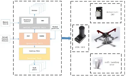
Figure 9. System structure of the quadrotor helicopter and the soft landing gear for the outdoor experiments.
The time-consuming complex tasks, such as path planning, GPS waypoint receiving, and manual switch engaging, are performed on the CU, which has an onboard processor. The position and altitude control are made on the FU. The FU receives speed values, hovering requirements, and landing tasks, sent from either the CU or from a human pilot equipped with remote controller (RC).
The integrated systems of the quadrotor helicopter are listed as follows:
• Flight System
Autopilot devices: The onboard flight assistant device is a Pixhack-V5 flight autopilot board. The board is based on the Pixhawk open hardware design; it runs PX4 on the NuttX OS and is fully compatible with the PX4 firmware [38,39].
Airframe: The structure of the quadrotor cross-shaped frame was built using polyvinyl chloride (PVC). The quadrotor UAV is equipped with four brushless DC motors and four Electronic Speed Controllers (ESCs).
Attitude and altitude control: The 3D position is estimated by jointly using IMU and GPS. Communication Protocol: The communication link used onboard is the Mavlink protocol. The IMU and the onboard processor use this protocol to send command data [40]. The UAV and GCS are connected through a universal asynchronous receiver/transmitter (UART).
• Landing System
Control devices: A PDMS-based four-finger soft landing gear mounted on the bottom the quadrotor body.
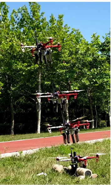
To evaluate the soft landing gear performance, twenty real field experiments were carried out in an open-space test field, as shown in Figure10. The flight tests were performed under different weather conditions. The external wind speed was below 5 m/s. To date, the quadrotor helicopter with soft landing gear has successfully achieved stable landing on non-flat surfaces by using the proposed control approach.
GCS. A human pilot took control over autopilot unit using the RC transmitter. Both personnel haD the option to send a full shutdown command to switch off all rotors immediately.
Figure 10. The proposed quadrotor helicopter system successfully landing on an outdoor non-flat surface with the support of the RBFNN controller.
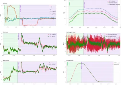
[image:13.595.227.369.573.603.2]During the experiments, the quadrotor helicopter attempted to land on a non-flat surface, as shown in Figure10, which is common in real-world situations. In each of these 20 experiments, the propsosed quadrotor helicopter successfully landed on a non-flat surface without rolling over. Figure11displays the velocity, attitude estimation, and altitude over time in the landing process. Table5shows the RMSE of the touchdown position related to the desired position, where the vertical errors were generated by the quadrotor speeds decreasing to zero before solid contact with the surface.
Table 5.Field landing position error.
RMSE HorizontalX,Y[m] 0.07
RMSE VerticalZ[m] 0.06
Impact absorbing tests were implemented by controlling the quadrotor landing with different descent speeds (0.5 m/s, 1 m/s, 1.5 m/s, and 2 m/s). The relative landing accelerations were obtained by the Pixhawk accelerometer. The peak accelerations during the landing impacts were 21 m/s2, 47 m/s2, 96 m/s2, and 194 m/s2, respectively. Therefore, the impact forces that the soft landing gear
Figure 11.Plots of the velocity, attitude, and altitude over time during the landing procedure.
6. Conclusion and Future Work
This paper demonstrates a quadrotor helicopter landing control procedure through an RBFNN-based backstepping control approach. First, a soft landing gear is designed that effectively absorbs the landing impact force. Second, an RBFNN-based backstepping control system is designed for the quadrotor helicopter. Third, a Lyapunov analysis is used to prove the stability of the proposed control system with external disturbances and uncertainties.
The soft landing gear and the RBFNN-based backstepping control methods work together to render the quadrotor helicopter system able to softly and precisely land on a challenging, non-flat surface. The effectiveness of the proposed RBFNN-based backstepping control strategy was further tested in field experiments. Future work will focus on enabling the quadrotor UAV to detect and choose the landing zone autonomously, without the support of GPS.
Author Contributions:Conceptualization, C.L.; Data curation, L.Y.; Funding acquisition, C.L.; Methodology, C.L.; Software, W.Z. and L.Y.; Visualization, W.Z.; Writing—original draft, C.L.; Writing—review & editing, C.L., Z.D., and L.Y.
Funding: The work was supported in part by the National Natural Science Foundation of China under Grant 61701541, in part by the Shandong Provincial Natural Science Foundation of China under Grant ZR2017QF003 and in part by the Fundamental Research Funds for the Central Universities under Grant 19CX02021A.
Conflicts of Interest:The authors declare no conflict of interest.
References
1. Ding, X.; Yu, Y. Motion Planning and Stabilization Control of a Multipropeller Multifunction Aerial Robot.
IEEE/ASME Trans. Mechatron.2013,18, 645–656. [CrossRef]
3. Rus, D.; Tolley, M.T. Design, fabrication and control of soft robots. Nature2015,521, 467. [CrossRef] [PubMed]
4. Omari, S.; Hua, M.D.; Ducard, G.; Hamel, T. Hardware and Software Architecture for Nonlinear Control of Multirotor Helicopters.IEEE/ASME Trans. Mechatron.2013, 18, 1724–1736. [CrossRef]
5. Zhang, G.; He, Y.; Dai, B.; Gu, F.; Yang, L.; Han, J.; Liu, G. Aerial Grasping of an Object in the Strong Wind: Robust Control of an Aerial Manipulator.Appl. Sci.2019,9, 2230. [CrossRef]
6. Lee, D.; Franchi, A.; Son, H.I.; Ha, C.; Bülthoff, H.H.; Giordano, P.R. Semiautonomous Haptic Teleoperation Control Architecture of Multiple Unmanned Aerial Vehicles. IEEE/ASME Trans. Mechatron. 2013, 18, 1334–1345. [CrossRef]
7. Johnson, A.; Montgomery, J.; Matthies, L. Vision Guided Landing of an Autonomous Helicopter in Hazardous Terrain. In Proceedings of the IEEE International Conference on Robotics and Automation (ICRA), Barcelona, Spain, 18–22 April 2005.
8. Templeton, T.; Shim, D.H.; Geyer, C.; Sastry, S.S. Autonomous Vision-based Landing and Terrain Mapping Using an MPC-controlled Unmanned Rotorcraft. In Proceedings of the IEEE International Conference on Robotics and Automation (ICRA), Roma, Italy, 10–14 April 2007.
9. Kendoul, F. Survey of advances in guidance, navigation, and control of unmanned rotorcraft systems.J. Field Robot.2012,29, 315–378. [CrossRef]
10. Barton, J.D. A Biologically-Inspired Micro Aerial Vehicle—Sensing, Modeling and Control Strategies.Johns Hopkins APL Tech. Dig.2012,31, 153–178.
11. Bosch, S.; Lacroix, S.; Caballero, F. Autonomous Detection of Safe Landing Areas for an UAV from Monocular Images. In Proceedings of the IEEE/RSJ International Conference on Intelligent Robots and Systems (IROS), Beijing, China, 9–15 October 2006.
12. Scherer, S.; Chamberlain, L.; Singh, S. Autonomous landing at unprepared sites by a full-scale helicopter.
Robot. Auton. Syst.2012,60, 1545–1562. [CrossRef]
13. Brockers, R.; Bouffard, P.; Ma, J.; Matthies, L.; Tomlin, C. Autonomous landing and ingress of micro-air-vehicles in urban environments based on monocular vision. In Proceedings of the SPIE 8031, Micro- and Nanotechnology Sensors, Systems, and Applications III, Orlando, FL, USA, 25–29 April 2011. 14. Cory, R.; Tedrakey, R. Experiments in Fixed-Wing UAV Perching. In Proceedings of the AIAA Guidance,
Navigation and Control Conference and Exhibit, Honolulu, HI, USA, 18–21 August 2008.
15. Zhang, K.; Chermprayong, P.; Tzoumanikas, D.; Li, W.; Grimm, M.; Smentoch, M.; Leutenegger, S.; Kovac, M. Bioinspired design of a landing system with soft shock absorbers for autonomous aerial robots. J. Field Robot. 2019,36, 230–251. [CrossRef]
16. Desbiens, A.L.; Asbeck, A.T.; Cutkosky, M.R. Landing, perching and taking off from vertical surfaces.Int. J. Robot. Res.2011,30, 355–370. [CrossRef]
17. Doyle, C.E.; Bird, J.J.; Isom, T.A.; Johnson, C.J.; Kallman, J.C.; Simpson, J.A.; King, R.J.; Abbott, J.J.; Minor, M.A. Avian-inspired passive perching mechanism for robotic rotorcraft. In Proceedings of the IEEE/RSJ International Conference on Intelligent Robots and Systems (IROS), San Francisco, CA, USA, 25–30 September 2011.
18. Nguyen, H.N.; Siddall, R.; Stephens, B.; Navarro-Rubio, A.; Kovaˇc, M. A Passively Adaptive Microspine Grapple for Robust, Controllable Perching. In Proceedings of the 2019 2nd IEEE International Conference on Soft Robotics (RoboSoft), Seoul, Korea, 14–18 April 2019; pp. 80–87.
19. Liang, X.; Fang, Y.; Sun, N.; Lin, H. Nonlinear hierarchical control for unmanned quadrotor transportation systems.IEEE Trans. Ind. Electron.2017,65, 3395–3405. [CrossRef]
20. Qian, L.; Liu, H.H. Path Following Control of A Quadrotor UAV with A Cable Suspended Payload Under Wind Disturbances. IEEE IEEE Trans. Ind. Electron.2019. [CrossRef]
21. Alexis, K.; Nikolakopoulos, G.; Tzes, A. Switching model predictive attitude control for a quadrotor helicopter subject to atmospheric disturbances.Control Eng. Pract.2011,19, 1195–1207. [CrossRef]
22. Wang, L.; Su, J. Robust disturbance rejection control for attitude tracking of an aircraft. IEEE Trans. Control Syst. Technol.2015,23, 2361–2368. [CrossRef]
23. Benallegue, A.; Mokhtari, A.; Fridman, L. High-order sliding-mode observer for a quadrotor UAV.Int. J. Robust Nonlinear Control IFAC-Affil. J.2008,18, 427–440. [CrossRef]
25. Wang, Q.; Wang, J.W.; Yu, Y.; Sun, C.Y. Robust attitude control of an indoor micro quadrotor with input delay. In Proceedings of the 2014 IEEE Chinese Guidance, Navigation and Control Conference, Yantai, China, 8–10 August 2014; pp. 2363–2368.
26. Rosales, C.; Soria, C.M.; Rossomando, F.G. Identification and adaptive PID Control of a hexacopter UAV based on neural networks. Int. J. Adapt. Control Signal Process.2019,33, 74–91. [CrossRef]
27. Furukawa, S.; Kondo, S.; Takanishi, A.; Lim, H.O. Radial basis function neural network based PID control for quad-rotor flying robot. In Proceedings of the 2017 17th International Conference on Control, Automation and Systems (ICCAS), Jeju, Korea, 18–21 October 2017; pp. 580–584.
28. Kantue, P.; Pedro, J.O. Nonlinear Identification of an Unmanned Quadcopter Rotor Dynamics using RBF Neural Networks. In Proceedings of the 2018 22nd International Conference on System Theory, Control and Computing (ICSTCC), Sinaia, Romania, 10–12 October 2018; pp. 292–298.
29. Bouabdallah, S.; Siegwart, R. Full control of a quadrotor. In Proceedings of the 2007 IEEE/RSJ International Conference on Intelligent Robots and Systems, San Diego, CA, USA, 29 October–2 November 2007; pp. 153–158.
30. Tayebi, A.; McGilvray, S. Attitude stabilization of a VTOL quadrotor aircraft. IEEE Trans. Control Syst. Technol.2006,14, 562–571. [CrossRef]
31. Sun, J.; Wang, Y.; Yu, Y.; Sun, C. Nonlinear Robust Compensation Method for Trajectory Tracking Control of Quadrotors. IEEE Access2019. [CrossRef]
32. Hoffmann, G.; Huang, H.; Waslander, S.; Tomlin, C. Quadrotor helicopter flight dynamics and control: Theory and experiment. In Proceedings of the AIAA Guidance, Navigation and Control Conference and Exhibit, Hilton Head, SC, USA, 20–23 August 2007; p. 6461.
33. Tran, D.T.; Nguyen, M.N.; Ahn, K.K. RBF Neural Network Based Backstepping Control for an Electrohydraulic Elastic Manipulator. Appl. Sci.2019,9, 2237. [CrossRef]
34. Ge, S.S.; Hang, C.C.; Lee, T.H.; Zhang, T.Stable Adaptive Neural Network Control; Springer Science & Business Media: Berlin, Germany, 2013; Volume 13.
35. He, W.; Chen, Y.; Yin, Z. Adaptive neural network control of an uncertain robot with full-state constraints.
IEEE Trans. Cybern.2016,46, 620–629. [CrossRef] [PubMed]
36. Peng, C.; Bai, Y.; Gong, X.; Gao, Q.; Zhao, C.; Tian, Y. Modeling and robust backstepping sliding mode control with Adaptive RBFNN for a novel coaxial eight-rotor UAV.IEEE/CAA J. Autom. Sin.2015,2, 56–64. 37. Slotine, J.J.E.; Li, W.Applied Nonlinear Control; Prentice Hall: Englewood Cliffs, NJ, USA, 1991; Volume 199. 38. Meier, L.; Tanskanen, P.; Fraundorfer, F.; Pollefeys, M. Pixhawk: A system for autonomous flight using onboard computer vision. In Proceedings of the 2011 IEEE International Conference on Robotics and Automation, Shanghai, China, 9–13 May 2011; pp. 2992–2997.
39. Meier, L.; Tanskanen, P.; Heng, L.; Lee, G.H.; Fraundorfer, F.; Pollefeys, M. PIXHAWK: A micro aerial vehicle design for autonomous flight using onboard computer vision. Auton. Robot.2012,33, 21–39. [CrossRef] 40. Marty, J.A. Vulnerability Analysis of the Mavlink Protocol for Command and Control of Unmanned Aircraft;
Technical Report; Graduate School of Engineering and Management, Air Force Institute of Technology: Wright-Patterson AFB, OH, USA, 2013.