Rochester Institute of Technology
RIT Scholar Works
Theses
Thesis/Dissertation Collections
9-1-2003
A Manufacturing Execution System using Siemens'
PC Based Automation Technology
Prakash Gandhi
Follow this and additional works at:
http://scholarworks.rit.edu/theses
This Thesis is brought to you for free and open access by the Thesis/Dissertation Collections at RIT Scholar Works. It has been accepted for inclusion in Theses by an authorized administrator of RIT Scholar Works. For more information, please [email protected].
Recommended Citation
A
Manufacturing
Execution System
using
Siemens'
PC Based
Automation
Technology
Prakash
Amar
Gandhi
M.S.
(Computer
Integrated
Manufacturing)
Thesis
submittedin
partialfulfillment
ofthe
requirementsfor
the
Master
ofScience in
the
department
ofManufacturing
Engineering Technology
in
the
College
ofApplied Science
andTechnology
ofthe
Rochester Institute
ofTechnology
COLLEGE OF APPLIED SCIENCE
&
TECHNOLOGY
ROCHESTER INSTITUTE OF TECHNOLOGY
ROCHESTER, NEW YORK
CERTIFICATE OF APPROVAL
MASTER OF SCIENCE DEGREE THESIS
The M.S. Degree Thesis of Prakash Amar Gandhi has been
examined and approved by the thesis committee as satisfactory for
the Thesis requirement for the Master of Science Degree in
Computer Integrated Manufacturing
Dr. Sudhakar R. Paidy
Dept. of Industrial and Systems Engineering
Kate Gleason College of Engineering
Prof. S. Manian Ramkumar
Dept. of Manufacturing and Engineering Technology
Permission granted
A Manufacturing Execution using Siemens' PC Based
Automation Technology
I, Prakash Amar Gandhi, hereby grant the permission to the
Wallace Library of the Rochester Institute of Technology to
reproduce my thesis in whole or part. Any reproduction will not be
for commercial use or profit.
Dedication
To
my
parents andfamily,
Acknowledgement
Throughout
the time
I have been
working
in
this
applied researchstudy,
many
peoplehave
assisted me.It
is impossible
to
acknowledgethem
all.Nevertheless,
I
wouldlike
to
specifically
thank the
following
individuals:
Dr.
Sudhakar
Paidy,
for
allthe time
he dedicated
to
my
research work andfor
the
knowledge he
shared with methroughout
the
course ofthis
study.This
thesis
would nothave
been
possible withouthis help.
Prof.
S.
Manian
Ramkumar,
for
his
continuous support and valuablecomments on
my
work.Mr. Dennis
Wilk,
Mr.
Barry
Hawley,
andMr.
Peter
Stansky
ofSiemens'
Energy
andAutomation
for
their
constanthelp
andtechnical
support.To Adwait
Palsule,
fellow
graduate researchassistant,
for his
support,
adviceand comments throughout
the
course ofthis
study.To
allmy friends
whohelped
mefrom
the
beginning
ofmy
thesis
for giving
valuable support and comments and
those
whohelped
meto
preparefor
the
Table
ofContents
Sections
Page No
Abstract
1
Introduction
1
2
Software Systems for
Manufacturing
4
2.1
Enterprise Resource
Planning
4
2.2
Manufacturing
Execution System
5
2.3
Control Layer
13
3
Structure
Query
Language
andNormalization
14
3.1
Structure
Query
Language
14
3.2
Normalization
15
4
Client-Server
methodology
for Data Management
21
4.1
Introduction
21
4.2
File Server
architectures22
4.3
Database Server Architecture
24
4.4
Three-Tier
Architecture25
4.5
Client/Server
issues
27
5
Open
Database
Connectivity
29
5.1
Introduction
toODBC
29
5.2
ODBC
Architecture29
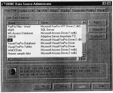
5.3
Data Source Name
31
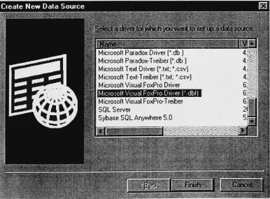
5.4
Visual FoxPro Connections
32
5.6
ActiveX
Data Objects
(ADO)
33
6
Siemens WinCC Features
37
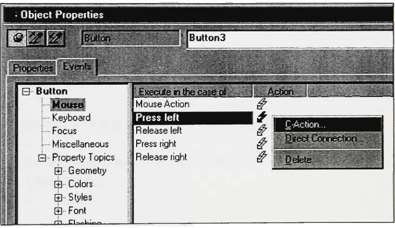
6.1
Functions
andActions
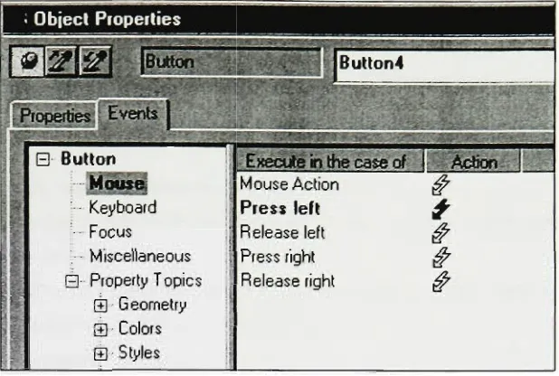
37
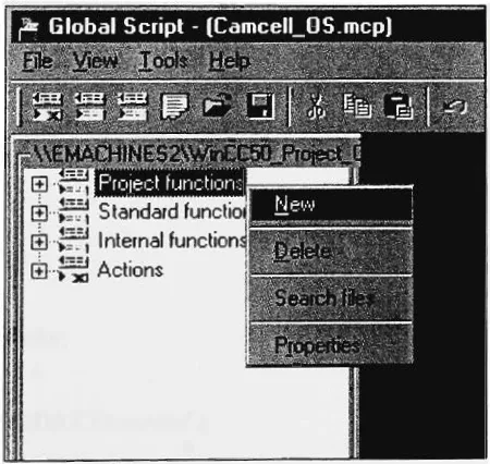
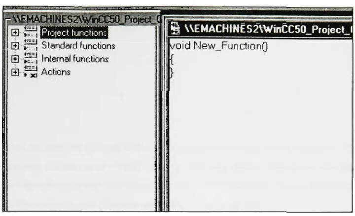
6.2
Global Script Editor
42
6.3
User Archive
43
6.4
Open database
46
7
Description
oftheCAMCELL
47
7.1
Manufacturing
andMaterial
Handling
47
7.2
Product/Process Flow
48
7.3
Computer Hardware Architecture
48
7.4
Software
Architecture andInformation
Flow
50
8
A CIM
database
for
Real-time data
57
8. 1
Data How from
ERPtoMES
57
8.2
Data flow between MES
andControl
layer
58
8.3
Dataflow
from
MES
toERP
67
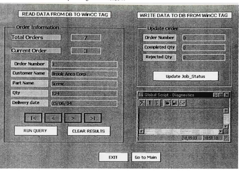
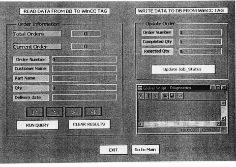
8.4
WinCC Interface
for
Workstations
67
9
VFP
screenfor
Database
74
9.1
Screen for
Shop
Manger
74
10
Conclusions
84
List
ofFigures
Fig
No.
Name
ofFigure
Page
No.
2
Software Systems for
Manufacturing
4
2.1
Integrating
Automation
systems toERP
6
2.2
The Evolution
ofManufacturing
Systems
7
2.3
MES
functional
model8
2.4
Real-Time Enterprise Management
12
3
Structure
Query
Language
andNormalization
14
3.1
The Raw
Database
16
3.2
The
First
Normal Form
17
3.3
The Second Normal Form
17
3.4
The
Third Normal Form
19
4
Client-Server
methodologyfor Data Management
21
4.1
Client/Server-computing
21
4.2
Applicationlogic
components22
4.3
File
server model23
4.4
Database Server
Architecture24
4.5
Three-tier Architecture26
5
Open
Database
Connectivity
29
5.1
ODBC
Architecture30
5.2
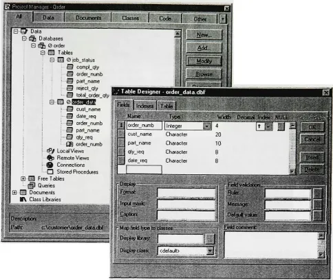
VFP
Connection Designer32
6
Siemens
WinCC
Features
37
6. 1
Actions
&
Functions
37
6.2
Types
ofTriggers
38
6.3
Range
ofFunctions andActions
38
6.4
The
Global Script Editor
43
Fi8
No-
Name
ofFigure
Page No.
6.6
WinCC Open
Database
46
7
Description
ofthe
CAMCELL
47
7.1
CAMCELL Hardware
Architecture
49
7.2
Data Flow
Diagram
I
52
7.3
Data Flow Diagram
II
55
8
A
CIM database
for Real-time
data
57
8
.1
ERP Layer
ofCAMCELL
5 8
8.2
MES Layer
ofCAMCELL
59
8.3
SCREW.SEQ
60
8.4
SEQ
File Format
60
8.5
SEQ
File
Topology
61
8.6
Dataflow between
MES
andcontrollayer
62
8.7
Order_Data WinCC
screen63
8.8
Control Layer
oftheCAMCELL
65
8.9
Read_SEQ
WinCC
screen66
8.10
Lathe
Station Operator Interface
69
8.
1 1
Mill
Station Operator Interface
70
8.12
Vision
Station
Operator
Interface
71
8.13
Shop
Supervisor Interface
72
8.14
Shop
Manger Interface
73
9
VFP
screenfor Database
74
9. 1
Main Menu
screen74
9.2
Authentication
screen75
9.3
Shop
Manager Menu
76
9.4
New Work Orders
(Scheduler/Manager)
78
9.5
Schedule
Analysis for
Planning
(Scheduler/Manager)
79
F'8
No-
Name
ofFigure
Page No.
9.7
Status
Analysis
o,9.8
Daily
report screengj
9.9
Performance
Menu
g2
9.10
Conformance
toSchedule
Appendices
No.
Appendix
A
Read
Data
from
FoxPro
Database
andWrite
toWinCC Tags
B
Write
Data
from
WinCC
tags toFoxPro
database
C
Real Time
Data
capturefrom
WinCC
into
FoxPro Database
D
Write Data
from
.SEQ and/or .SQXfile
toWinCC
tagsE
Handles
for
Runtime Archive Functions
Abstract
The focus of any manufacturing operation is to establish better yields, reduced cycle times, increase
quality, and handle dynamic demand/resource fluctuations. Over the past few years many manufacturing
companies have implemented Enterprise Resource
Planning
(ERP)
systems and they have provedthemselves to besuccessful in achievingthese goals.
However,
real-timedata is requiredinordertoportray an accurate account of theday-to-day
and/orhourly
product manufacturing operations. Retrieval ofthisreal-lime data is a challenging task. A
Manufacturing
Execution System(MES)
is a real-time information system that improves the performance of the shop floor operationsby linking
business planning, orderentry, materialmanagement,purchasingandaccountingto thecontrols onthe
factory
equipment.Siemens'
PC-based automation technology is an emerging technology that appears to provide a robust
architecture for
integrating
all elements of the manufacturing environment. Applications that range fromsimple control todistributedcontrol and full-fledged MEScanbe developed usingSiemens' architecture. The primary focus of this thesis is applied research to facilitate the development of a
Manufacturing
Execution System to control a flexible manufacturing system,CAMCELL,
usingSiemens'
PC-based
automation technology and Microsoft's database technology. CAMCELL contains two CNC machining
centers, assembly robots, and a vision system, all of which are interlinked
by
a materialhandling
system. The software architecture of the CAMCELL is based on NIST's five level hierarchy.Specifically,
itcontains functional modules for order entry, scheduling, and routing. In addition to these functional
modules, there are various support modules. In this study, we have developed software architecture to
achieve vertical integration ofthe process control layer, the MES layerand the ERP layer.
Using
Siemens' WinCC software, real-time process data was collected and integrated into an MES database. The studydemonstrates howorderinformation stored ina high-level databaseisconvertedintouseful information for
the control layer. The study also demonstrates the ability of WinCC and Visual FoxPro to update the
production data into the MES database. Various Operator interface and database screens are proposed for
Section
1.
Introduction
The
key
to any production plant is the ability to capture real-time parameters and influence the businessprocess.
However,
the volume of information and the speed requirements make it impossible for human interference.Nevertheless,
over the past few years, manufacturing companies have implemented largeEnterprise Resource
Planning
(ERP)
systems, which have proven to be very effective. It has been achallenge,
however,
to retrieve critical data from the manufacturing shop floor. This data is required in order to portray an accurate account of theday-to-day
and/orhourly
product manufacturing operations. The solution is aManufacturing
Execution System (MES): a path that connects the shop floor to thetop-flooroperations.1
Several companies that offer control and human/machine interfaces
(HMI)
are providing totalindustry
solutions that may include the following: control hardware and software, advanced control applications, material
handling
equipment, andManufacturing
Execution System(MES)
software. For example, Siemens SIMAT/C IT Production Suite is the collection of components todesign,
manufacture andmaintain
Manufacturing
Execution Systems. SIMATIC IT Framework is a collection ofhighly
integratedcomponents designed to integrate the systems within each
factory,
standardize production across the entire enterprise andkeep
manufacturing processes aligned with supply-chain activity.By linking
andcompletelyintegrating
the worlds of production and management with one standard software, the SIMATIC IT Framework creates effective communications and process synchronization and coordination throughout aplant orseriesof plants.
2Camstar's leading
Manufacturing
Execution Systems(MES)
forglobal enterprises monitor and synchronize manufacturing activities across globally distributed plants, and link them in real time to the enterprise. These systems, based on Camstar's InSiteSuite,
track products and orders on the plantfloor,
collect transactions for reporting to back-office applicationsincluding
ERP and CustomerRelationship
Management (CRM), and electronically dispatch these orders or productrequirements to the shop floor personnel. The InSite trackingframework alsoprovideskey
data services to the shop floor and theyincluding
real-time quality data checks, yield monitoring, automatic system actions, and lot traceabilityfor improved qualityandprocess.3
CIMNETproducesa configurable
Manufacturing
ExecutionSystem
(MES)
called Factelligence, which manages manufacturing shop floor operations, and providesthecritical link to fill the manufacturinggap between Enterprise Resource
Planning
(ERP)
and thefactory
floor. The CIMNET product utilizes the latest Microsoft Web and Oracle databasetechnology
toelectronically manage production schedules, documents, product quality, machine efficiency, material
yields andlabortime.
Since MES projects involve extensive system integration services, manufacturers need to be careful in
selecting a supplier. Companies selecting MES vendors who need to be assured that their prospective partner willbecapableof an ongoingrelationship,areavailable tosolve problems and updatethe system.5
The Siemens' PC-based automation technology is an emerging technology that appears to provide robust
architecture for
integrating
all elements of the manufacturing environment. Applications ranging from simplecontrolto distributedcontrol andfull-fledged MEScanbedevelopedusingSiemens'
The primary focus of this thesis is applied research
leading
to facilitate the development of aManufacturing
Execution System to control a flexible manufacturing system usingSiemens'
PC-based
automation technology and Microsoft's database technology. CAMCELL is used as a test bed. It is a
flexible manufacturing system containing two CNC machining centers, assembly robots, and a vision
system, all of which are interlinked
by
a materialhandling
system. The software architecture of theCAMCELL is based on NIST's five level hierarchy.6
Specifically
itcontains functional modules for orderentry, scheduling androuting. Inaddition to thesefunctional modules, thereare various supportmodules. This study aims to
develop
software architecture and information flow in the CAMCELL to achievevertical integration. The study also aims to evaluate the Siemens' Automation System in terms of its
important features in the context of Systems Integration. Various process control system applications are available that can acquire large quantities ofdata from the manufacturing process into a
database,
thereby providing dataforthe officearea orthird-party
systems. Theseprocess control applicationsarealsocapableofpassing the information in a reverse direction. Data forproduction originating in the enterpriselevel are handed over to the automation level
by
these software's. Process control applications also provide HMIs for the operators toview the work recipes and generatereports formanagement toanalyze the production. This studyaims atstudying theSiemens' Automation Systemthrough theseperspectives.In Section
Two,
the evolution of the manufacturing system and howManufacturing
ResourcePlanning
(MRP)
gave birthtoEnterprise ResourcePlanning
(ERP)
systemswillbediscussed,
including
the functions ofMES in an informationsystem architecture.Thissectionalsodescribethecontrol layerof afactory. In SectionThree,
StructuredQuery
Language,
which is a standard language for many relationaldatabases,
will be discussed. The section will also analyze the normalization concept and three normal forms in a
database.
In Section
Four,
the client/server computing, which is one of the widely used forms of distributed computing, will be discussed. The study will discuss presentationlogic,
processing, and the storagecomponent of client/server architectures. The three types of client/server architecture - File
Server,
Database Server and Three-Tier architecture ~
are alsodescribed. This section contains abriefdescription on requirements forsuccessful implementationofclient/server projects.
Section Five will discuss Microsoft's Open Database
Connectivity
(ODBC)
interface that helps toaccessdata from a variety of database management systems. It describes four components of the ODBC architecture viz., Application, Driver Manager, Driverand the Datasource. The section will also overFile and machine Data Source Name (DSN). The section
briefly
describes Remoteviews in Visual FoxPro that facilitate theexternal data through ODBC.Finally
it,
describes ActiveX DataObjects(ADO)
and the stepsinvolved inconnecting toadatabase throughscripts.
Section Six will discuss one ofthe importantcapabilities ofWinCC, that
is,
capturing real-time data from the field deviceinto aMES database. This section elaborates on UserArchiving
and Global Script editorsdescribes the Open architecture of
WinCC,
which makes it capable of exchanging information with theenterprise and
factory
levelsofthe MES database.Section Seven considers the CAMCELL through four different perspectives viz. the
Manufacturing
andMaterial
Handling,
Product/Processflow,
Computer hardwarehierarchy
and the Software Architecture and Information flow perspective.This sectiondescribes the proposeddatabase architecture of aManufacturing
Execution System forthe CAMCELLmanufacturingcell.Section Eight examines the data flow between
ERP,
MES and the Control layer of a CAMCELL automation system. It describes the actual implementation ofSiemens'
automation and Microsoft's database technology in the CAMCELL. The section probes theestablished the procedure to read and write
to and from WinCC and VFP databases. It also describes the steps involved in capturing real-time data
from CAMCELL into aMES database. Proposed WinCC interface for workstationsare also developed in this section.
Section Nine targets, will discuss the proposed VFP database screens for various users in the system. The
concludingsection summarizesthefindingsofthis applied research study.
References:
'Manufacturing
ExecutionServices, Inc.(2002)
<www.mes-erp.com/MES solution.htm>
2Siemens
AG(2003),
IndustrialSolutionsand Services (I&S). (7July
2003)
<www.is.siemens.de/itps/en/index.htm>
3Camstar
Inc.(2003)
<www.camstar.com/products/insite.asp>
4Cimnetinc
Inc.(2002)
<www.cimnetinc.com/>
intelligent
Manufacturing.(1997)
- LionheartPublishing
IncSection 2.
Software
Systems
for
Manufacturing
2.1 Enterprise Resource
Planning
Since the
Nineties,
ERP systems have gained an explosive popularity among manufacturing enterprisesworldwide. An ERP (Enterprise Resource
Planning)
system isan integrated information processingsystemsupportingvarious businessprocesses,such as
finance,
distribution,
humanresources,andmanufacturing.Traditionally,
companies developed separate computer applications to satisfy the needs of each of theirfunctional segments, such as accounting, purchasing,
inventory
and planning. Such systems grew asinconsistent islands of
information; hence,
theirconsolidation wasnot possible when deemednecessary. Asa result, decision-makers were denied access to timely information for making urgent business decisions.
This gave rise to the development of an integrated system to be known as ERP that would address the
informationrequirementsofcorporateheads.
Material requirementplanning
(MRP)
and manufacturingresourceplanning (MRPII)
did provide a certainlevel ofintegration.
However,
they primarily addressedthe requirements of amanufacturingset-up. On theother
hand,
ERP addressed the information requirements of the entire enterprise.Moreover,
it was notrestricted to the current requirements of an organization but provided an opportunity for continuously
improving
andrefining businessprocesses.ERP vanquishes the old stand-alone computer systems in
finance, HR,
manufacturing and the warehouse,and replaces them with a single unified software program divided into software modules that roughly
approximate the old stand-alone systems. Finance, manufacturing and the warehouse all still gettheirown
software, except now the software is linked together so that someone in finance can look into the
o
warehouse softwaretoseeifan orderhas beenshipped.
Manufacturers who implemented Enterpriseresourceplanningare
finding
ways toextendthe usefulness ofERPas abackboneof
distributing
corporateinformationacrosstheenterprise.For a manufacturing company employing traditional manufacturing facilities and conventional MIS
(Management Information
Systems),
FMS and ERP Systems may bethe two majorareas ofinvestment foracompany tostaycompetitive.
The amount of investment for a typical FMS is about $5-10 million
(US),
and a typical ERP system ishavea suitable
Manufacturing
Execution System(MES)
that can providean adequateinterface between thetwo.7
Over the past few years, many manufacturing companies have implemented ERP (Enterprise Resource
Planning)
systems and have proved themselves successful.However,
it has been challenging to retrievereal-time data from the shop floor. This data is required to
keep
an account ofday-to-day
and/orhourly
productmanufacturingoperations.2.2
Manufacturing
Execution System
MESA international defines MES as "Systems that deliver information enabling the optimization of
production activities from orderlaunch to finished goods.
Using
current and accurate real-time data, MESguides, responds to, and reports on plant activities asthey occur. The resulting rapid response to changing
conditions, coupled with a focus on reducing non-value added activities, drives effective plant operation
and
processes."1
An MES
(Manufacturing
ExecutionSystem)
enables an enterpriseto use standard software across multipleplants to optimize production process and connect the plants into enterprise supply chains. MES provides
an enterprise wide, real time view ofthe complete manufacturingenvironment. Itcloses the gap between theERPandproduction worldsforoptimal
results.10
The classical model of Computer Integrated
Manufacturing (CIM)
is divided into three layers:Planning,
Execution and Control. The
Planning
layer includesERP,
Supply
Chain Management(SCM)
andAdvanced
Planning
andScheduling
(APS)
systems.9
The control layer includes all real time shop floor
control systems such as
PLC,
SCADA,DCS,
CNC/DNCmachines etc. MESoccupies themiddleexecutionlayer and knits the manufacturing processtogetherintoan integrated whole, closing thegap between
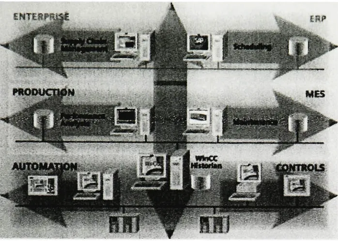
Figure2.1:
Integrating
Automationsystemsto ERP112.2.1
Evolution
ofmanufacturing
systems2The first computerized business systems were used in accounting.
By
the late 1960s or early1970s,
from these accounting systems evolved material requirements planning (MRP), which was intended tohelp
manufacturers betterplan material availability (Figure 2.2).
By
the late 1970s and early 1980s, computers were more powerful and capable ofhandling
more dataand werebeing
usedinteractively
by
more people. MRPevolved into MRP II as shop floor reporting systems, purchasing systems and related functions wereadded.
MRP II didn't address the requirements of
forecasting
and managing demand indistribution,
nordid it do much of ajob in managing activities that tookplacethere. Toaddress the requirements indistributing
andforecasting,
Distribution ResourcePlanning
(DRP)
was developed.Similarly,
MES and qualitymanagement evolved. Though these systems helped the manufacturers to solve business-related problems,
they lacked integrationwith othersystems. In theearly 1990s,the ERP evolved andtook theplace ofMRP II while DRP grew into
Supply
chain management and the shop floor solutions evolved into integrated [image:19.612.134.483.84.333.2]The Evolutionof
Manufacturing
SystemsMES
l-MES
F/S
Aitountinji
: ERP^
\
Nl
^recasting
Supply
|
Chain Mgmt
|
DRPLegend: MES-ManufacturingExecution Systems
FV5 Focused Solutions
ERP>Enterprise Resource Manning
Figure2.2The Evolutionof
Manufacturing
Systems2.2.2
MES in
theinformation
systems architecture:MES is one of several types of major information systemdesigned for manufacturing companies. Eachof
these system categories include various functions and product types. Some of the other software systems
thatinteractwithMES are
briefly
described below2.2.2.1 EnterpriseResource
Planning
(ERP):ERP is a manufacturing information system whose focus goes beyond
inventory
control and distributedmanagement activities. It consist ofthose systems that automate core corporate activities, such as
finance,
manufacturing, marketing, human resource and supply-chain management. It is a customize software
system thathandles themajority of
enterprises'
information system requirements. It iscan be consideredto
be an optimum method of connection between different subsets of manufacturing systems via computer
systems.
2.2.2.2
Supply
Chain Management (SCM):A supplychain is a network offacilitiesand distribution options thatperformthe functionsof procurement
ofmaterials, transformation ofthesematerials intointermediate andfinished products, andthe distribution
of these products to customers.
Supply
chains exist in both service and manufacturing organizations,although the complexity of the chain may vary greatly from
industry
toindustry
and firm to firm.5 Itincludes functions such as
forecasting,
distribution andlogistics,
transportation management, electronicv>;.Vji%iSK
Figure 2.3 MES functionalmodel
2.2.2.3
Supply
andServiceManagement (SSM):This comprises software for sales force automation, product configurations, service quoting, product
returns, and so forth.
2.2.2.4 Productand Process
Engineering
(P&PE):Includes computer aided design and manufacturing (CAD/CAM), process modeling, and product data
management(PDM).
2.2.3
MES
functions:4There are eleven functionsofMES that linkto othersystems in different ways
by
product or needs(figure2.3)
Resourceallocation andscheduling
Operations/Detail scheduling
Dispatching
production unitsDocumentcontrol
Datacollection/Acquisition
Quality
managementProcess management
Maintenancemanagement Product
tracking
andgenealogy Performance analysisEach ofthe functions contributesto collection ofdata in orderto monitor, track, and estimate costs, andto
control products manufactured inreal time.
2.2.3.1. Resource Allocationand Status:
This manages resources
including
machines, tools, labor skills, materials, equipment, and other entitiessuch as documents that must be available in order for work to start. It provides a detailed
history
ofresources and insuresthatequipmentis properly setup for processing and provides status inreal time. The
management of these resources includes reservation and
dispatching
to meet operation-schedulingobjectives.
2.2.3.2. Operations/DetailScheduling:
Provides sequencing based on priorities, attributes, characteristics, and/or recipes associated with specific
production units at an operation. It influences factors such as shape, color sequencing, or other
characteristics that, when scheduled in sequence properly, minimize set-up. It is finite and it recognizes alternative and overlapping/parallel operations in order tocalculate, in
detail,
the exacttime of equipmentloading
adjusted toshift patterns.2.2.3.3.
Dispatching
ProductionUnits:Manages flow of production units in the form of
jobs,
orders,batches, lots,
and work orders. Dispatch information is presented in the sequence in which the work needs to be done and changes in real time asevents occur on the
factory
floor. It has the ability to alter the prescribed schedule on thefactory
floor. Reworkand salvage processes are available, as well asthe ability tocontrol theamountof workinprocessat anypoint withbuffermanagement.
2.2.3.4. Document Control:
Controls records/forms that must be maintained with the production unit,
including
workinstructions,
recipes,
drawings,
standard operationprocedures, partprograms, batchrecords,engineeringchangenotices, shift-to-shift communication, as well as the abilityto edit "asplanned"and"as
built"
information. Itsends
instructions down to the operations,
including
providing datato operators or recipes todevicecontrols. It might also include the control andintegrity
of environmental, health and safety regulations, and ISO2.2.3.5. Data Collection/Acquisition:
Provides an interface link toobtain the inter-operational production and parametricdata from theforms and
records that were attached to the production unit. The data may be collected from the
factory
floor eithermanually orautomatically from equipment inan up-to-the-minute timeframe.
2.2.3.6.LaborManagement:
Provides a status of personnel in an up-to-the-minute time frame. Includes time and attendance reporting
and certification tracking, as well as the ability to track indirect activities such as material operations and
analysisfroma
laboratory
informationmanagement system(LIMS)
could alsobe included.2.2.3.7.
Quality
Management:Provides a real-time analysis of measurements collected from manufacturing to assure proper product
quality control and to
identify
problems requiring attention. It may recommend action to correct theproblem,
including
correlating the symptoms, actions and results to determine the cause. It may includeSPC/SQC tracking and management of off-line inspection operations, and an analysis from a
laboratory
informationmanagementsystem
(LIMS)
could alsobe included.2.2.3.8. Process Management:
Monitors production and either automatically corrects or provides decision support to operators for
correcting and
improving
in-process activities. Such activities may be inter-operational and focusspecifically on machines or equipment
being
monitored and controlled, and/orintra-operational,
which istracking the processfrom one operationtothe next. It may includealarm management tomake sure
factory
personnel are aware of process changes that are outside acceptable tolerances. It provides interfaces
between intelligentequipment and
MES,
possiblythroughDataCollection/Acquisition.2.2.3.9. Maintenance Management:
Tracks and directs the activities to maintain the equipment and tools, and to insure their availability for
manufacturing,
including
scheduling for periodic or preventive maintenance. This also provides the response(alarms)
to immediate problems. It maintains ahistory
of past events to aid indiagnosing
newproblems.
2.2.3.10. Product
Tracking
and Genealogy:Provides visibility for
determining
where work is at all times and its disposition. Status information may include who is working onit,
as well as components, materialsby
supplier,lot,
serial number, currentproduction conditions, and any alarms, rework, or other exceptions related to the product. The on-line
tracking function creates a historical record, as well. This streamlines the process of
tracing
components2.2.3.11. PerformanceAnalysis:
Provides up-to-the-minute reporting of actual manufacturing operations results along with comparisons to
past
history
and expected business results. Performance results include such measurements as resourceutilization, resource availability, product unit cycle time, and conformance to schedule and performance to
standards. It may include SPC/SQC. Performance Analysis draws on information gathered from different
functions that measure operating parameters. These results may be prepared as a periodic report or presented on-line as current evaluation ofperformance.3
2.2.4 MES function in
afactory
Figure 2.4describesthe data flow between ERP
(Business),
MES (Execution),andControls layers.ERP systems work with time spans of
days,
weeks, months, and years. The ERP system notes productusage, customerorders, andmaterialrequirements, andsendsrequeststo theexecution
(MES)
layer.MES makes wise manufacturing decisions for a company. MES develops the work instruction for the
control layer. The MES systems are responsible for carrying out product manufacturingand all operations associated with thecreation ofthoseproducts. Product design detailscanbestored attheMES
layer,
which supplies instructions to the control layer on how tobuild the product. The MES system worksin shorttimespans of one
day,
oneshift,onehour,
minute orsecond.1
Once thecontrol parameterssuch as
instructions,
programs,
documents,
software, and othermanufacturingrequirements for supportsystemsare
transmitted, the control layeris then responsible for carrying outthe
process. Thecontrollayerworksinreal-time (with atimefactoroflx).
Real-Time
Enterprise
Management
(MIES inanBntorprteeDatanow)Order Status WDStatus
QjuaJtyData
Btrfld
Mstoiy
Manufacturing
Execution System
Control system{or IOperation)
ChecksResources
ManuTaetL.ringPlan
WorkOrder*
Trees* WIP DisplaysOperator Instructions
Upeates ERP System
Operation/JobStatus
MacMna/Oparator Status ProcessValues
100x iox IX
Time
FactorFigure2.4Real-Time EnterpriseManagement
2.3 Control Layer
The components of the Control Layer include programmable controllers, computers, robots, DCSs
(Distributed Control
Systems),
sensingdevices,
Computerized NumericControllers,
user/operatorinterfaces,
human-machineinterfaces,
andintelligent input devices.Thecontrol layer focuses on production line and processdecisions. MES transmits
instructions,
programs,documents,
software,and othermanufacturing requirementsforsupportsystems tothecontrollayer,
which,in turn,uses all the
hardware,
software andpeopletocarryouttheprocess.The shop floor (Control
layer)
is a constantly changing environment. A time factor of lx (less than asecond) means there are operations always occurring torefine or correct the process to maintain desired
outputs. The
"Equipment","
People",
and"Devices"
Thus,
MES provides the real-time visibility of all plant data so that scheduling and planning software can optimize production. It providesa meaningfulrelationship between businessdataandfactory
data.References:
'MESA
International-WhitePaper Number3,
Controls Definition & MES toControls Data Flow Possibilities.(February
2000).MESA International-WhitePaper Number
5,
Execution-DrivenManufacturing
Management forCompetitiveAdvantage. (1997).
3MESA
International-White Paper Number4,
MES Software Evaluation / Selection. (1996).4MESA
International-White Paper Number6,
MES Explained: A High Level Vision.(1997, September).Ganeshan,
R. &Harrison,
T.P. An introductiontosupplychain management. (1995,May
22). <http://lcm.csa.iisc.ernet.in/scm/supply_chain_intro.html>Welti ,
N.,
& deSchepper,
A. (1999). Successful sap R/3 implementation: PracticalmanagementofERPprojects.
Addison-Wesley
LongmanPublishing
Co.,
Inc.,Boston,
MA.7Kim,
D. K (1996). G7 advancedmanufacturingsystem project: System integration for FMS. ProjectReport,
TongilHeavy
Industries Co.Ltd., Korea.8Koch,
C. The ABCofERP. (2002,February
7). <www.cio.com/research/erp/edit/erpbasics.html>9Siemens
Automation Drives<www.siemens-industry.co.uk/automation-solutions/industrial.asp>
10Sober
IT.(2001,
March).<www.soberit.hut.fi/T-86/T-86.141/s2001/seminarslides/Automation_ERP.pdf>
"Siemens
Business Integration.(2003)
Section 3.
Structure
Query
Language
andNormalization
3.1 SQL (Structured
Query
Language)
SQL is a simple butpowerful database language that is the standard language for many relational database
systems. Some common relational database management systems that use SQL are
DB2, Oracle,
Sybase,Microsoft
SQL,
Informix etc. Although mostdatabase systems useSQL,
mostofthem also have their ownadditional proprietaryextensions that are most often usedonlyon theirsystem.
However,
thestandard SQLcommands such as
"Select", "Insert", "Update", "Delete", "Create",
and"Drop"
can beused to accomplish almosteverythingthatone needstodo witha
database.1
3.1.1 TypesofSQL
Statements2
Standard SQLstatementscan besubdividedinto 3 distinctgroups
3.1.1.1 DataDefinitionLanguage
(DDL)
Statements:Data Definition Language is a set ofSQL commands used to create modify and delete database structures
(not data). These commands wouldn't normally be used
by
a general user, who should be accessing thedatabase via an application.
They
are normally usedby
the DBA (at least to a limited extent), a databasedesigner or an application developer. These statements are immediate and are not susceptible to
ROLLBACKcommands.
Anybody
using DDL must have the CREATEobject privilege and a Tablespaceareainwhichto create objects.
Createtable:creates an emptytablethat
defining
itsstructure.Drop
table: destroysatableand all thedataitcontains (but onlywithpermission).Altertable:changesthe definitionofthe table(column namesand types,etc.).
3.1.1.2 DataManipulation Language
(DML)
statements:Data Manipulation Language is the areaofSQLthat permitsdatachangesallowsyoutochangedata within
thedatabase. Itconsists ofonlythreecommand statementgroups,theyare
Insert,
DeleteandUpdate.Insert:adds aroworpartof arowtoatable.
Update: modifies the entries foraselectedrow.
3.1.1.3 Data
Query
Language(DQL)
statements:Data
Query
Language is the area ofSQL that allows access to data in the database and ability to imposeordering upon it. Ilconsists ofSelectstatements only.
Select: The SELECT statement is the heart ofSQL. It gets the data out ofthe database for manipulation.
When SELECT is performed against a table or tables, the result is compiled into a further but temporary
table,whichisdisplayed (orreceived
by
the program).3.2
Normalization4Normalization is the process oforganizing data in adatabase.This includescreatingtablesand establishing
relationships between those tables according to rules designed both to protect the data and to make the
databasemore flexible
by
eliminating redundancyandinconsistent dependency.Redundant data wastesdisk space and creates maintenance problems. If data that exists in more than one
place must be changed, the data must be changed in exactly the same way in all locations. A customer
address change is mucheasier to implement ifthat datais stored only inthe Customers table and nowhere
elseinthe database.
There are a few rules for database normalization. Each rule is called a "normal form." Ifthe first rule is
observed, thedatabaseis saidtobe in "firstnormal form."
Ifthe firstthree rules areobserved, the database
is considered to be in "third normal
form."
Although other levels of normalization are possible, third
normalform isconsideredthe highestlevel necessary formost applications.
Inadiscussionofnormalization, the
following
conceptsapply:Entities- Entitiesare real world objects orconcepts
(customer,
department,
product)
Relationships
-Relationship
describes how two or more entities interact (customer hasproperty, departmentproducesproduct,producthasprice)
Tuples- Eachrow, whichis called aTuple. A Tuple is an instanceofanentity orrelationship
orwhateverisrepresented
by
therelation.Attributes - Attributes describe properties of entities and relationships (customer name,
departmentnumber,quantityofproduct sold).Eachcolumn iscalledanAttribute.5
Primary
Key- Eachrowis uniquely identifiedby
means of aprimarykey. Itsvalue shouldbeForeignKey- An attribute inthe
current table thatis the primary
key
in othertable.Composite key- When a
combination of attributes is used as a unique identifier, it is known
as a compositekey.
Entity
Integrity- Theentity
integrity
rule states that for every instance of an entity, thevalueofthe primary
key
mustexist, must be unique, and must not be null. Without entityintegrity,
theprimary
key
could not fulfill itsrole ofuniquelyidentifying
eachinstanceof an entity.Referential Integrity- The referential
integrity
rule states that every foreignkey
value mustmatch a primary
key
value in an associated table. Referentialintegrity
ensures that userscancorrectlynavigate betweenrelatedentities.
3.2.1 The RawDatabase3
A database that is notnormalized may include data that is contained in one or moredifferent tables for
no apparent reason. This could be bad for security reasons, conservation ofdisk space usage, speed of
queries, efficiency ofdatabaseupdates, and, perhaps most
importantly,
dataintegrity. A database beforenormalization is one that has not been broken down
logically
into smaller, more manageable tables.Figure 3.1 illustratesthedatabase usedforthisbookbeforeitwas normalized.
CCfl*rtV_DABASe
*mpw atAji
last rame cua nems
flwt_nam* eu addreu frtdce_rBm cusCdly
addwss eud.state
cly eu*_zkp
nam ns!i phorB
IP cuaUox
phont od_num
pagw fr
portion ora data
ijatojir* pfOdJH
fxrf raw pfoeLde^c
bonus COS
<_te_tat..raJM
Figure3.1 The Raw Database
3.2.2 The Normal Forms
Normalformis awayofmeasuringthe
levels,
ordepth,
towhich adatabase has beennormalized.The
following
arethe threemost common normal forms inthe normalization process:The first normalform
Thesecond normalform
Ofthe three normal
forms,
each subsequent normal form depends on normalization steps taken in theprevious normal form. For example, to normalize a database using the second normal
form,
thedatabase must firstbe in the firstnormal form.
3.2.2.1 TheFirst NormalForm3
The objectiveofthe first normal formis to dividethe base data into logical unitscalled tables. When
each table has been
designed,
a primarykey
is assigned to most or all tables. Figure3.2,
illustrateshowtheraw
database,
showninthepreviousfigure,
has beenredevelopedusing thefirstnormal form.np_id sWSLnsvn* an ptano paper *T..V psy_ntt bonis *t#_t*8t_reiss nvjd JULneme rroddta najne r* prune pager poMon pay/Ble bonis 0ar*_lMLr#s* EA8ASE cusTc*fl_Ta. cuah3 CVtf.W ajst.nam QjH.nan*
eutf Md>f>*t ejei_*jr*M
cuS.cly cud.dty
cust_0ssie aMjAMs
eu*1.> euu^ilp
CUS pi-o-si cjajnont
euA.tM cuKkn
onJ.^risTO Oftl/vm ** <tt omLMM _ <xtiji* prodjd praeLe**: ant PftOOUCTS. T6L ptod.M pwd_*C cod
Figure3.2 The FirstNormal form
Youcan see that toachievethe firstnormal
form,
data had tobe broken into logicalunits, eachhaving
aprimary
key
and ensuring thatthere are no repeated groups in any ofthe tables.Instead of onelargetable, there are now smaller, more manageable tables:
EMPLOYEE_TBL,
CUSTOMER_TBL,
andPRODUCTS_TBL. The primary keys are normally the first columns listed in a table, in this case:
EMPJD,
CUSTJD,
andPRODJD.3.2.2.2TheSecondNormal Form
The objective ofthe second normal form is to take data that is only partly dependent on the primary
key
and enterthatdataintoanothertable. Figure3.3 illustratesthesecond normalform.According
to thefigure,
the second normal form is derived from the first normal formby
furtherEMPLOYEE.TBL lUTtpjtJ Luinam* miiSM nsvn* Ml** o*T Male tOn poaflcr.oosc ptty.n*; bona CUSTOMEB_TBL cu_l cuajKura cua^oty cual.st.i* cjs rt-cuSLphonc ord.run prod_M EW.OYEE.TBL cKy Ml* nc P*9 EMPLOVEE_PV_TBL emp.KJ posJDur pet*on.awe
>TO1Mr* ptty.ndi bona CUSTOMS^TBI cw_id cuti_ramo cu_cflr cu**,Hp CUst_ttt OflOS^3_TH. Ofl)_nim proa W crt.data
FIRSTNORMALFORM SECOND NORMAL FORM
Figure 3.3 Thesecond normalform
EMPLOYEE_TBL is split into two tables called EMPLOYEE_TBL and EMPLOYEEJ>AY_TBL.
Personal employee information is dependent on the primary
key
(EMP_ID),
so that informationremained in the EMPLOYEEJTBL (EMPJD,
LAST_NAME, FIRST_NAME,
MIDDLE_NAME,
ADDRESS, CITY, STATE,
ZIP,
PHONE,
and PAGER). On the otherhand,
the information that isonly partly dependent on the EMPJD (each individual employee) is used to populate
EMPLOYEE_PAY_TBL (EMPJD,
POSITION, POSITION_DESC,
DATE_HIRE, PAY_RATE,
DATE_LAST_RAISE). Notice that both tables containthe columnEMPJD. This is the primary
key
ofeachtableand isused tomatchcorresponding data betweenthe two tables.
CUSTOMER_TBL is splitinto two tablescalled CUSTOMER_TBLand ORDERS_TBL. Whattook
place is similar to what occurred in the EMPLOYEE_TBL. Columns that were partly dependent on
theprimary
key
weredirected to anothertable. The order information fora customer is dependentoneach
CUSTJD,
but does notdirectly
depend on the general customer information in the originaltable.
3.2.2.3 The ThirdNormalForm3
The third normal form's objective is to remove data in a table that is not dependent on the primary
EMPLCVEE^PAY.TBL
mp to
pooiv poslv "
1
wane I C1e_.rwepiyrata bonus
CMB_lBS(_ni
Eh*=lO'iTiE_W_TBl
Posmows.Ta. ecnMkin
<Wk_f*o
pjy_rat Pcrui
pOsttXXI
posstan.aesc
cM*_l_rBa
Figure 3.4 Thethirdnormalform
Another table was created to
display
the use of the third normal form. EMPLOYEEJVWJTBL issplit into two tables, one table containing the actual employee pay information and the other
containing the position
descriptions,
which really do not need to reside in EMPLOYEE_PAY_TBL.ThePOSITION_DESCcolumn istotally independentoftheprimary
key,
EMPJD.3.2.3Benefits ofNormalization3
Normalization provides numerous benefits to a database. Some of the major benefits include the
following:
Greateroverall databaseorganization
Reduction of redundantdata
Data consistency withinthe database
Amuch more flexibledatabase design
Improved database security
Organization is brought about
by
the normalizationprocess, making thejobeasierforeveryone, fromthe user who accesses tables to the database administrator
(DBA)
who is responsible for the overallmanagement of every object in the database. Data redundancy is reduced, which simplifies data
structures and conserves disk space. Because duplicate data is minimized, the possibility of
inconsistent data is greatlyreduced. Forexample, inonetableanindividual'sname could read STEVE
SMITH,
whereas the name ofthe same individual reads STEPHEN R. SMITH in another table. Adatabase that has been normalized and broken into smaller tables provides more
flexibility
as far asmodifying existing structures. It is much easierto modify a small table withlittle datathan to modify
one
big
table thatholds all the vital data in the database.Lastly,
security is also provided inthe sensethat the DBA can grant access to limited tables to certain users.
Security
is easier to control whennormalizationhasoccurred.
3.2.4 Referential
Integrity
Referential
integrity
simply means that the values of one column in a table depend on the values of acolumn inanother table. For
instance,
in orderfor a customertohave a record in the ORDERS_TBL, there mustfirst be a record forthatcustomer in theCUSTOMER_TBL table.Integrity
constraints canalso control values
by
restricting a range of values for a column. Theintegrity
constraint should beincluded in the table'screation. Referential
integrity
is typically controlled through theuse ofprimaryand foreignkeys.
In a table, a foreign
key,
normally a singlefield,
directly
references a primarykey
inanother table toenforce referential integrity. In the preceding paragraph, the CUSTJD in the ORDERS_TBL is a
foreign
key
thatreferencesthe CUSTJDin theCUSTOMER_TBL.3.2.5 Drawbacksof
Normalization3
Although most successful databases are normalizedto some
degree,
thereis one substantial drawbackwith of a normalized database: reduced database performance. The acceptance of reduced
performance requires the knowledge that when a query ortransaction requestis sent to the
database,
there are negative factors
involved,
such as CPU usage, memory usage, and input/output (I/O). Anormalized database requires much more
CPU,
memory, andI/Oto processtransactions anddatabasequeries than does adenormalized database. A normalized database must locate the requested tables
and thenjoin the datafrom the tables toeither getthe requestedinformationortoprocess the desired
data.
Reference:
'Jupitermedia
Corporation,(2003)
<www.SQlcourse.com/intro.html>
2Angell
Developments<www.ilook.fsnet.co.uk/ora sql/sqlmain.htm>
3Plew,
R.R. &Stephens,
R.K.. (2000).Sams TeachYourself
SQL in 24 Hours. SamsMicrosoft
KnowledgeBase Article-209534(2002)
<support.microsoft.com/default.aspx?scid=KB.en-us;q209534>
5Brown,
C.E.DatabaseLearning
Module. (2001).Section 4.
Client-Server
methodology
for Data
Management
4.1
Introduction1Today,
stand-alone computershave beenreplacedby
computersin networks formostprocessing tasks.The use of multiple computers linked
by
a communications network for processing is calleddistributed processing. In contrast with centralized processing, in which all processing is
accomplished
by
one largecentralcomputer, distributedprocessing worksamongPCs, minicomputers,and mainframesthatare linked together.
One widely used form of distributed computing is client/server computing. Client/server systems
operate on networkenvironments,splitting theprocessingof an applicationbetweenafront-endclient
and a back-end processor. Client/server describes the relationship between two computer programs
where one program is where the client makes the request from another program, the server, which
fulfillsthe request.Figure 4.1. Illustratesthe client-servercomputingconcept.
^
CUE**F
InterfaceJ
f^Merfx*
J
fw^
j
'
f
littoi
Figure4.1
Client/Server-computing
The several client/server architectures that have evolved can be distinguished
by
the distribution ofapplication logic components across clients and servers. As illustrated in
Figure2,
the applicationI<
L
Presentation
Logic
Input
Output
Processing
Logic
I/O
Processing
Business
rulesData
Managment
Storage Logic
Data
Storage
andretrieval
n
"-"
Figure 4.2 Application logiccomponents2
The first is the "presentation logic component"
(See Figure
4.2)
.The presentation logic is concernedwith managing the graphical user interface. It isresponsible for
formatting
and presenting data on theusers screen or other output
devices,
and for managing user input from keyboard or other inputdevices.2
The second component is the processing components also know as the Business service layer. It is
responsible for
implementing
businessrules that are specific to a company or procedure and act asabridge between thepresentation layers. It alsohandles data processing
logic,
businessruleslogic,
anddata management logic. Data processing logic includes activities such as data validation and
identification of process errors. Business rules that have not been coded at the DBMS (DataBase Management
System)
level may be coded in the processing component. Data management logic iswheretheparticular recordsthatareneededfora particulartransactionaredetermined.
The third componentis storage; it is responsible foractual retrieval or storage ofdata from or to the physicaldevice.
4.2 File Server
architecturesThe original PC networks were based on a file server, where the data manipulation occurs at the
desktop
where the datawas requested. The clienthandled thepresentationlogic,
processing logicand much of the storage logic.By
contrast File server is a device that manages files operations and isclient, one where most ofthe process occurs on theclient PC ratherthan on a
server.2
Refer to figure
4.3
In these types of systems, clients run the DBMS software. When the user request some
data,
forexample usingthe SQL (Structured
Query
Language),
the DBMS at theclient sidedecideswhichfiles itneeds fromthe servertoprocessit.Thesefiles arethen requested fromthe server.Thus,
there isone database but many concurrent copies of theDBMS,
one on each of the active PCs. All the datamanipulation isperformed attheclient workstation and not on thefileserver.
Therefore,
afilesserver actsonlyas a storagedevice. Theclienthandles alldatamanagementfunctions.In the
1990s,
PC LAN (local area network) computing changed because the capacity of the filesharing was strained as the number ofonline users grew (one LAN can only satisfy about 12 users simultaneously) and graphical user interfaces
(GUIs)
became popular(making
mainframe and terminaldisplays appearout-of-date). PCsare nowbeing
used inclient/server architectures.GteM
Prce*s/*eiSafcle*
Appficagwnprogram
- use*mterfac* - djtobcnc
processing - goiwade quorate Hindismwgrttytwidsapuriy *PutDBMS
2Ei
~T,Cfcm
RH*satedate
Requeststolockdata En&rReorfdate Lock sSitui
;?!)%4*ar*9
'
Ss^r-dbcking
/ActaBib*ahdcfeAtodie* StgnfcomLAHtraffic
Figure 4.3 Fileserver model
Theseare thelimitations whenusing fileservers onLAN :
1)
There is a considerable movement across the network. A full functional copy ofDBMS is required at the client side; even if few records are required the whole file containing them mustbe passed.Thus,
the serverdoes very little work andtheclientisbusy
performing data manipulation. These types ofsystems place considerable burden on the client workstationandcreateahigh networktraffic load.
2)
Since the client workstation does the processing, each end user whose workrequiresheavy
and frequent database access needs a high-performance computer with plenty of memory.amount of data that can reside on the PC while a transaction is
being
processed. The fileserverdoes not need much RAM and need notbeavery powerfulPCsinceit does little work.
3)
TheDBMS copy ineach workstation must manage theshareddatabase integrity. In addition,each application program must recognize, for example, locks and take care to initiate the
proper locks. The developers must understand how their application will interact with the
DBMS's concurrency, recovery and security controls, and sometimes must program such
controlsintotheirapplications.
4.3 Database Server Architecture
Database ServerArchitecture (also known as 'Twotier client/serverarchitecture") was developed in
the 1980s from the file server software architecture design. In this type of architecture, the client
workstation is responsible for managing the user
interface,
including
presentationlogic,
dataprocessing logic and businessrules
logic,
and the database serverisresponsible for database storage,access and
processing.2
With thistypeofsystem,thedatamanagementlogic issplitbetween theclient
and server. The LAN traffic is reduced because the DBMS is placed in the server, and only those
records aretransmitted thatmatchthe requestcriteria. Inresponseto a useraction, theclient sends an
SQLrequestto the server that executes it andreturns or modifies data in the database appropriately.
The Central DBMS function is referred to as aback-end
function,
whereas the application functionsrunningontheclient sideare referred as front-endprograms. Figure 4.4shows typicaldatabaseserver
architecture.
Figure 4.4 Database Server
Architecture2
1)
Withthis type ofarchitecture only thedatabase server requiresprocessingpower adequateto handle thedatabase sincethedatabase is stored onthe server and noton theclient.2)
The databaseserver can be tuned tooptimizedatabase-processing
performance.2
3)
Thenetworktraffic is considerably reducedbecause lessdata istransmitted acrosstheLAN.4)
User authorization,integrity
checking, datadictionary
maintenance and query and updateprocessingare all performedin one
location,
onthe databaseserver. 2LimitationsofDatabase Server Architectureare:
1)
The Clientsideisrather"fat" dueto thebusiness logicthat residesthere.2)
Changes to the business logic at the server also require changes to presentation layer. Thiswill requirethateach clientbe upgraded separately.
3)
Two-tierarchitecture provides limitedflexibility
in moving programfunctionality
from oneservertoanother without manually regeneratingprocedural code.
These drawbacks todatabase server architecturehave ledtothepopularityofthree-tierarchitecture.
4.4 Three-Tier Architecture
Three-tier software architecture emerged in the 1990s to overcome the limitations of the two-tier
architecture (See Figure 4.5). A middle tier is added between the user's system interface client
environment and database management server layer. Often application programs reside on an
additional server, which is referred to as an application server. But the additional server may hold a
local database while another serverholdstheenterprisedatabase.
There are avariety of waysof
implementing
this middle tier, suchastransactionprocessing monitors,mail servers, or application servers. The middle tiercan perform queuing, application execution. For
example, ifthe middletierprovides queuing, theclientcan deliverits requestto the middle layerand disengage because the middletier will access thedata and return the answer to theclient. Inaddition
the middle layer adds scheduling and prioritization for work in
progress.3
In many situations most
business processing occurs on the application server ratherthan on the client workstation ordatabase
Cl*nlLaytW
C*e**
Apfrtcamon
swvef
Figure 4.5 Three-tierArchitecture2
Three-Tier Architecture isalso referred toasn-tier, multi-tier,or enhanced client/serverarchitectures.
Three-Tier Architecturecan provide severalbenefits2:
1)
Scalability: Three-Tier Architectures are more scalable than two-tier architectures. Forexample, the middle tier can be used to reduce the load on a database server
by
using a transaction-processing(TP)
monitor to reduce the number of connections to a server, andadditional application servers can be added to distribute application processing. A TP
monitor is a program that controls data transfer between clients and servers in order to
provide a consistentenvironmentforonlinetransactionsprocessing (OLTP).
2)
Technological flexibility: It is easy to change DBMS engines, though triggers and storedprocedures will need toberewritten with a three-tierarchitecture. The middle tiercan even
bemovedtoadifferentplatform.
3)
Lower long-term cost: Use of off-the-selfcomponents or services in the middle tier canreduce costs, as can substitution of modules within an application rather than an entire
application.
4)
Better match of systems to business needs: Newmodules can be buildto support specificbusinessneeds rather
building
moregeneral,completeapplications.5)
Improve customer service: Multiple interfaces on different clients can access the samebusinessprocess.
6)
Competitiveadvantage:The abilitytoreact to businesschangesquicklyby
changing smallmodulesofcode ratherthanentireapplicationscanbe usedtogain a competitiveadvantage.
7)
Reducerisk:Again,
theabilitytoimplement small modules of codequicklyandtocombinethem with code purchased from vendors limits the risk assumed with a
large-scale
4.5 Client/Server issues
In order to succeed, client/server projects should address a specific business problem with a
well-defined
technology
and cost parameters. Certain areas should be carefully addressed in order toimprove the chancesfor
building
asuccessfulclient/server application:2Accurate business problem analysis: Just as in the case ofothercomputing architectures, it is
critical to
develop
a sound application design and architecture for new client/server systems.Developers,
tendency to pick thetechnology
and then fit the application to itseems to be morepronounced inthe strong push towardclient/server environments thathas occurred inthe last six
years. It is more appropriate to accurately define the scope of the problem, determine the
requirements, and thenusethat informationtoselectthe technology.
Detail architecture analysis: It is also important to specify the details of the client/server
architecture.