-~ ,
APPLIED DA
APPLIED DATA SYSTEMS, INC . .ELECTRONIC INSTRUMENTATION AND CONTROLS
ElECTR )NIC INS
ROBERT KONDNER
ELECTRONIC ENGINEER
981 1 MALLARD DR. SUITE 213
LAUI EL. MD. 20708
VectorScan 512
Programmer's Manual
Version 1.3
APPLIED DATA SYSTEMS, INC.
9811 MALLARD DRIVE, SUITE 213 LAUREl, MARYLAND 20708
elECTRONIC INSTRUMENTATION AND CONTROLS
VectorScan 512
Programmer's Manual
Version 1.3
VectorScan 512 Table of Contents
TABLE OF CONTENTS
1 . INTRODUCTION . . . 2
1 . 1 SCOPE . . . 2
1 . 2 MANUAL OVERV lEW . . . 2
2. OVERVIE\Il . . . 3
3 . INSTALLATION . . . 4
4 . OPERATION . . . 7
4 .1 SETUP . . . 7
4 .2 OPERAT I ONAL MODES . . . 7
4 . 3 CONTROL COMMAND SEQUENCES . . . 8
4 .4 GRAPH I CS COMMANDS . . . 9
4.4.1 INTRODUCTION TO GRAPHICS COMMANDS . . . 9
4.4.2 SET PLOT LEVEL (LEV) . . . 11
4 . 4 . 3 PLOT PO I NT (P) . . . 1 1 4.4.4 DRAW VECTOR (VEC) . . . 12
4 . 4 . 5 DRA\Il ARC (ARC) . . . 1 2 4.4.6 DRAW CIRCLE (CIR) . . . 12
4 . 4 .7 F ILL SCRE EN (F I L) . . . 13
4.4.8 FILL AREA (PFL) . . . 13
4 . 4 . 9 CHANG E LEV E L S (C H G) . . . . 1 4 4.4.10 GRAPHICS CURSOR ON (GCN) . . . 15
4.4.11 GRAPHICIS CURSOR OFF (GCF) . . . 15
4.4.12 GRAPHICIS CURSOR POSITION (GCP) . . . 15
4 . 4 . 1 3 E NTE R TE X-T ( TXT) . . . . 1 5 4.4.14 SCALE CHARACTERS (SCL) . . . 16
4 . 4 . 15 CHARACTER CURSOR POS ITl ON (CRS) . . . 16
4 .4.16 PRINTER SPOOLER MODE (PSM) . . . · . . . 17
4.4.17 PRINT HARD COPY (PHC) . . . 17
4.4.18 DEFINE SCAN LEVELS (DSL) . . . 17
4.4.19 DEFINE COLOR SEQUENCE (DCS) . . . 18
4.4.20 SYNCHRONOUS MODE ON (SON) . . . 18
4.4.21 SYNCHRONOUS MODE OFF (SOF) . . . 18
4.4.22 SET SCREEN BOTTOM (SSB) . . . 19
4.4.23 INTERLACE ON (ION) . . . 19
4 . 4 . 2 4 I NT E R LAC E 0 F F (. I 0 F) . . . . 1 9 4.4.25 SET USER CHARACTER (SUC) . . . 19
4.4.26 DRAW USER CHARACTER (DUC) . . . 19
4.4.27 ENABLE XON/XOFF HANDSHAKE (EXH) . . . 20
4.4.28 DISABLE XON/XOFF HANDSHAKE (DXH) . . . 20
4.4.29 PRINT STRING DIRECT (PSD) . . . 20
4.4.30 LOAD MAP REGISTER (LMR) . . . 21
4.4.31 BINARY POINT PLOT (BPP) . . . 21
4.4.32 BINARY FILL SCREEN (BFS) . . . 21
4.4.33 PRINT HORIZONTAL (PH) . . . 22
4.4.34 PRINT VERTICAL (PH) . . . 22
4 . 4 . 35 DOTTE D LINE ( DOT) . . . 22
4.4.36 AND/XOR MODE (AXM) . . . 23
4 . 4 .37 CHANGE CONTROL CHARACTER (CCC) . . . 23
4.4.38 LOAD VIDEO CONTROLLER (LVC) . . . 23
APPENDIX 1- COMMAND SUMMARy . . . 24
APPENDIX 2- ACCESS TO JUMPERS AND FUSE . . . 25
APPENDIX 3- SERIAL CONFIGURATION JUMPER SETTINGS . . . 26
APPENDIX 4- SUPPORTED GRAPHICS PRINTERS . . . 28
APPENDIX 5- DOWNLOADABLE CHARACTER FORMAT . . . 29
APPENDIX 6- CONTROL COMMANDS (I@I COMMANDS) . . . 32
VectorScan 512 1 Introduction
VectorScan 512 Introduction
SECTION 1 - INTRODUCTION
1.1 SCOPE
This document describes the characteristics, the VectorScan 512.
operation and maintenance procedures for
1.2 MANUAL OVERVIEW
This manual consists of 4 major sections. Section 1 introduces the manual. An overview of the VectorScan is provided in section 2. Section 3 provides information on how the external hardware is connected to the various rear panel connectors. Section 4 describes the details of both the software and hardware interface. Also in section 4 are the detailed descriptions of the VectorScan commands.
Several appendices have been added for a quick and easy reference to VectorScan commands and configuration jumper settings. Other topics such as control commands and programmable shape formats are included.
Additional copies Data Systems Inc.
VectorScan 512 3 Overview
SECTION 2 - OVERVIEW
The VectorScan 512 is a low cost, high resolution color graphics controller which operates under the supervision of a host computer. It is an intelligent, microprocessor based peripheral that accepts high level graphics commands to produce images on an RCB color monitor. The VectorScan connects easily to any computer with an RS232 serial port. A second port is provided so that the VectorScan may be connected "between" a computer and terminal. In this configuration, the RS232 port already available for the user console can be used for graphics. The VectorScan will be dormant until activated by a special
control sequence.
This simple interface allows the VectorScan to be connected to almost any computer. Vith the high level graphic commands and a RS232 interface, the VectorScan is well suited for use over low speed telephone lines with a modem. Since all commands are transfered via the RS232 port in a printable ASCII format, both software and hardware can be transfered from one computer to another. Application programs can be written in any high level language witho~t the use of special machine dependent subroutines.
The display is 512 pixels wide by 480 pixels high and is available in 4, 8, and 16 colors or gray scales. The colors are selectable from a palette of 16 color/intensity combinations via a mapping register. Sixteen gray scales are also selectable using the mapping register. The VectorScan provides both an RCB/sync interface for a color monitor and a composite video/sync interface for a monochrome monitor.
Also standard on the VectorScan is a Centronics parallel interface which may be connected to a low cost dot matrix printer. The VectorScan contains software to drive a numb~r of common printers to provide a hardcopy output of the graphics display. A special printer spooler mode is provided to allow the 64k, 96k, or 128k byte memory to be used as a printer queue.
Commands for drawing points, lines, circles, and arcs are provided as well as screen and area f i l l commands. Text may be displayed in either a horizontal or vertical format using the built in ASCII character set. Text may be positioned anywhere on the screen and scaled in both the x and y dimensions. A downloadable shape table can be used to provide a user programmable character set. Each command is described in detail in section 4, OPERATION, and a concise command summary is contained in Appendix 1.
VectorScan 512 4 Overview
SECTION 3 - INSTALLATION
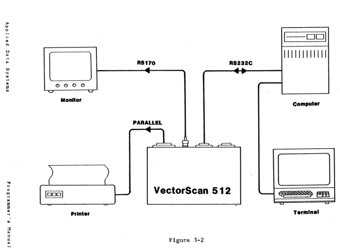
The VectorScan 512 has six connectors located on the rear panel. They are power, terminal, computer, color video, monochrome video, and printer. Figures 3-1 and 3-2 show two
typical configurations of a system incorporating a VectorScan .
./
The VectorScan should be connected to a 110 to 120 VAC 50/60 Hz power source via the equipment cord supplied.
The rear panel connector labeled "COMPUTERII should be connected to a standard RS232 port on a computer or modem. The baud rate, number of stop bits, number of data bits, and parity may be selected via jumpers located under the top panel. Appendix 2 describes how to access these jumpers and appendix 3 describes
the jumper settings.
The rear panel connector labeled "TERMINALII may be connected to a terminal, but this connection is not crucial to the operation of the VectorScan. It is provided so that the VectorScan may be inserted "between" the computer and a terminal, thus allowing the VectorScan to be added to systems without an extra RS232 port. This connection is also useful when using the VectorScan at a remote location via a modem. The baud rate, stop bits and parity for this port are the same as for the "COMPUTER" port described above.
The nine pin "0" connector provides the RCB/sync signals for driving an RGB color monitor. The signals provided are Red, Green, Blue, Intensity, Horizontal sync, Vertical sync, and Ground. All signals are positive TTL levels. Appendix 7 l i s t s
the pinout of this connector.
The BNC video output jack on the rear panel provides a 2.0 volt RS170 composite video signal for operating a monochrome monitor. This should be connected to a standard RS170 monochrome monitor. While the VectorScan will accomodate any standard RS170 monitor, it is recommended that a high persistence phosphor (eg. P 39) be used to reduce the effects of interlace flicker.
>
u
'0
..
-III
a.
t:J lQ
t+
ru
til
'<
tn
t+
II) (!)
(!) .C!> (!)
S
III '-' '-J
Monitor
10001
-Printer
R!l70
RS232C
...
~
'
...
PARALLEL
RS232C
...
.,
...
I
9
r- ""'"' r-' ......
....
VectorS can 512
Flgure 3-1
I
Dol
IIIII1I11 , II
Computer
Termln ••
<:
II)
n
....
0t1
til I') III
~
(II
... N
'-II
...
o
»0 '0 '0 ...
-ro
0.
t j PI
,.,.
fIJ
RS170
R8232C
to ~ ~
...
'< ~
...
tn
,.,.
ro (!) (!) (!)
0
a
tn '-J ' - J
Monitor
PARALLEL
~
~
1
r J
VectorScan 512
10001
..---Printer
Figure 3-2
I
DDI
IIII11111111
Computer
-1;;;.1
Termine.
<
"
n,.,.
0
t'1
(1l
n
PI ::t
(.II
....
N
....
::2
tn
,.,.
PI
...
...
PI
,.,.
....
o
[image:9.804.29.732.53.565.2]VectorScan 512 7 Operation
SECTION 4 - OPERATION
4.1 SET UP
The VectorScan can be connected in either of the two configurations shown in figures 3-1 and 3-2. The configuration depicted in figure 3-1 is for using the VectorScan "between" a terminal and the computer. In that configuration the VectorScan normally passes all data transparently between the computer and terminal. Special control commands can be issued to activate the VectorScan and/or to inhibit data from being passed to the terminal. Hence, in this conf iguration, the VectorScan may be added to a system without the need for an extra serial port or i t may be used to provide graphics at a remote location. In the configuration shown in figure 3-2 the VectorScan is connected to a dedicated port and no terminal need be connected. A terminal can, however, be added in this configuration for debug purposes. <Note that the VectorScan does not respond to input from the terminal port.) If the VectorScan is connected to the printer port of the computer then, when i t is not being used for graphics, it can be used in the spooler mode to speed listings. The special control sequences for activating the VectorScan and inhibiting the terminal are applicable in either configuration. It is important to note that the terminal data input is ORed with the VectorScan serial output to the computer. Hence care should be taken not to use the terminal while the VectorScan is actively producing serial output data. The VectorScan uses two protocols for throttling the computer commands. The XON/XOFF <control Q control S) protocol is available for software handshaking and the DTR (Data Terminal Ready) line can be used to provide a hardware handshake. The DTR handshaking is always enabled. The XON/XOFF software handshaking may be enabled or disabled with VectorScan commands.
4.2 OPERATIONAL MODES
The VectorScan operates in one of several modes depending on the commands it receives. These are the transparent, graphics, hardcopy, and spooler modes. In each of these modes the VectorScan may be operated in half or full duplex and the
terminal port .may be enabled or disabled.
The VectorScan defaults to the transparent mode at power up or can be placed in the transparent mode by an "@O" command sequence. In the transparent mode, the VectorScan examines the data being received via the "COMPUTER" connector and searches for control command sequences ignoring everything else. The VectorScan will remain in the transparent mode until it receives an "@C" command sequence.
~hen the VectorScan the graphics mode.
VectorScan 512 8 Operation
data stream being received via the "COMPUTER" port as graphics commands. This data is also sent to the terminal port unless that port has been inhibited. If the VectorScan is in full duplex while in the graphics mode then it will echo all characters it receives and return error indications for invalid commands. The VectorScan has a 128 character input FIFO to buffer incoming data. If that FIFO becomes full, the VectorScan will throttle the host computer by either forcing low the DTR line on the serial interface (Pin 20 "COMPUTER" connector) or by sending an XOFF (control S), depending on the configuration selected. As the FIFO empties, the VectorScan will again allow serial input by either sending an XON (control Q) or asserting the DTR line. From the graphics mode the VectorScan can be placed in the transparent mode by receiving the command sequence "@D". Any commands in the input FIFO when the "@DI/ is received will be executed. The VectorScan does not place the I/@"
commands in the input FIFO but, instead, interprets them immediatley.
The hardcopy mode is used to copy the image in screen memory to the attached graphics printer. The VectorScan can be placed in the hardcopy mode only from the graphics mode and will return to the graphics mode when the hardcopy is finished. While in the hardcopy mode, the VectorScan's command FIFO can be filled with graphics commands.
The printer spooler mode of the Ve~torScan is used to allow a listing to be queued in screen memory. This mode can only be entered from the graphics mode. While in the spooler mode, the VectorScan uses screen memory as a buffer thus destroying any
image that may have been there.
4.3 CONTROL COMMAND SEQUENCES
The VectorScan accepts commands received over the "COMPUTER" port. These commands fall into two main catagories - operating commands, described in subsequent sections, and control commands which are described here. The format of the control commands is an "@" followed immediatly by the command character. This two character command must be the first sequence of characters on a
lin~ in order for i t to be interpreted as a control command. (Note that a new line is defined by a carriage return followed by any number of line feeds or nulls. This control command syntax was chosen because i t is unlikely to appear in normal text and because some systems will trap nonprinting control codes.) A l i s t of the control command sequences accepted by the VectorScan and their meanings is contained in appendix 6. All the control sequences are passed to the attached terminal unless it has been inhibited. Control sequences are never echoed to the host computer.
The VectorScan may be enabled (graphics mode) or disabled ( t r a. n spa. r en t mod e ) b Y the con t r 0 1 comma n d s II @C " and " @D II
VectorScan 512 9 Operation
disable VectorScan output to the computer when the VectorScan is i n t h e 9 rap h i c s mod e . "'h en the Ve c tor S can r e c e i v e s a n "@F" i t ceases to put data for the computer in i t s output FIFO, however
the current contents of the output FIFO are sent. "'hen the VectorScan output is enabled, via an "@£", the VectorScan will begin putting data in the output buffer to send to the computer. Any commands that have already been received but not yet processed (ie. in the input buffer) will produce output. Note that the XON/XOFF input control will be used by the VectorScan whether or not the VectorScan's output is enabled (if this handshaking protocol has been selected).
The output data to the terminal can be enabled or inhibited by using the II@A" and II@BII commands respectively. The VectorScan defaults to a terminal enabled ("@A II ) condition. Note that the terminal input through the VectorScan to the computer is always enabled.
Finally, the II@R" command has been provided to reset the VectorScan regardless of i t s current state. This command forces the VectorScan to execute its power up procedures which initializes all variables and modes to their defualts. The current command is aborted immediatly (including hardcopy and printer spooling operations) and the unit is placed in i t s
transparent mode. The screen is cleared and the sign on message is displayed. Note that the downloadable user shape table is not affected.
4.4 GRAPHICS COMMANDS
4.4.1
This section describes the graphics VectorScan 512.
INTRODUCTION TO CRAPHICS COMMANDS
commands offered by the
VectorScan 512. 10 Operation
coordinate. The pixel in the lower left corner of screen memory is 0,0 and the pixel located in the upper right corner of screen memory is 511,511. Note that screen memory is 512x512 but that only 512x480 pixels are displayed. A command is provided which specifies which Y coordinate will be on the lowest line of the display. Note that the X,Y coordinate system is referenced to the video memory not the screen display. Hence, if the Y coordinate of the lowest screen line is not 0, then the point 0,0 will not be in the lower left corner of the screen. Care has been taken in the design of the VectorScan to provide a one-to-one aspect ratio on the screen so that no special scaling will be required of the host computer.
If any command is issued which would cause the VectorScan to compute a pixel coordinate outside of the 0 to 511 range available, the VectorScan will plot that pixel modulo 512. This res u Its i n a .. w rap a r 0 un d " e f f e ct. An e x amp l e o f a c 0 mm.a n d t hat
would cause wrap around is drawing a circle with a radius of 1000.
The VectorScan is capable of displaying a pixel in one of sixteen colors/gray scales. The gray scales are numbered in order of increasing intensity, with zero the darkest and fifteen the most intense. Most of the plotting and drawing commands are uni-color. (That is they use only one color when executed>. The plot color may be set or changed at any time and remains in effect until a new plot color is selected.
With the exception of the control command sequences (ie the "@" commands), all VectorScan -commands have the following format. Each command must start on a new line and may be preceded by any number of spaces. The command token is from one to three upper case letters and no imbedded spaces are allowed. The command token terminates when either a character other than an upper case letter or the third upper case letter is received. The command token is then immediatley evaluated to determine if the command is valid. If the command is not valid then the VectorScan will indicate this by responding with a II?" and a bell. (Of course if the VectorScan's output has been disabled by an"@F" comma n d seq u e n c e , the Ve c tor S can wi I I not ret urn the error message.) If the command token is valid then the VectorScan will parse the rest of the line for parameters. If an invalid parameter is received or ~f the wrong number of parameters Is received the VectorScan will issue the error response just described. Any number of spaces (or tabs> between tokens (ie. command tokens and parameters> is allowed. Numeric parameters are specified in decimal and do not require leading zeros. Numbers must be specified as integers and must not include a sign or decimal point. Commands that require the address (x,y coordinate) of a point may use a 11+11 to indicate
that the coordinate of the graphics cursor. (The exceptions to this are the binary mode commands. These commands are used to reduce the number of bytes required to specify a command.>
4.4.2
4.4.3
VectorSc.an 512 1.1 Operation
they should be sent to the VectorScan (ie. as a sequence of upper case letters). The parameters, if any are required, will be shown as lower case letters. The actual parameters sent to the VectorScan should be numbers (or the appropriate ASCII character in the case of binary mode commands)
SET PLOT LEVEL (LEV)
As described above, all uni-color commands (ie. commands requiring only one plot color) will use the level last selected. The color (level) selected using this command determines the value of pixels to be plotted in video memory and is independent of the map register setting. The sixteen levels are numbered from 0 to 15. Another level (16) may be specified which will put the VectorScan in a special highlight mode. In this mode, existing pixel levels are increased by 8 (modulo 16) instead of being written over. This feature allows a drawn shape (eg. circle or line) to be erased by simply re-drawing that same shape. (Any level plus 16 is equal to the original level.) Drawing a shape in this special manner allows that shape to be vis i b 1 e i n a n y b a c k g r 0 un d. ( Not e t hat the f i l l i n g' comma n d s d 0
not use this highlighting feature. The f i l l commands will use the last absolute level specified. See section 4.4.8 for more i n f o.r mao t ion 0 f a r e a f i l l i n g . )
Th e .. LEV II comma n d wi l I s e 1 e c t the p lot I eve I
subsequent uni-color commands. The format of the is
LEV z
to be used for "LEV" command
where z is a number between zero and sixteen, with sixteen used to activate the highlight mode. Note that whenever the LEV command is used any previous AXM commands will over-written. The new AND ma s k wi l I b e z e r 0 , the X OR ma s k wi l i b e set t 0 z. (5 e e
section 4.4.36 for AXM command description.)
PLOT POINT (P)
The liP" memory.
the last command.
command is used to plot a point in the The point will be plotted using the plot
IILEV" command or the mask set specified The format of the plot command is
P
x
ywhere K is the x coordinate of the point and y is the y coordinate
512x512 image level set wi th wi th an AXM
4.4.4
4.4.5
4.4.6
VectorSca.n 512 12 Operation
command plots points relative to 0,0 in image memory (which may not be the lower left corner of the screen display depending on
the currently selected bottom screen coordinate).
DRAW VECTOR (VEC)
The "VEC" command is used to draw a vector (a line), current plot level, between two specified endpoints. The of the vector command is
VEC xl y1
where xl is the y1 is the x2 is the y2 is the
DRAW ARC (ARC)
x2 y2
x coordinate y coordinate x coordinate y coordinate
of of of of
the the the the
first endpoint first endpoint
second endpoint and second endpoint
The "ARC" command is used to draw an arc in level. The forma.t of the "ARC" command is
the current
ARC x y r pl pZ
where
x is the x coordinate of the center of the arc y is the y coordinate of the center of the arc r is the radius of the circle containing the arc pI is the start angle of the arc and
pZ is the end angle of the arc
in the forma t
plot
The start and end angles (pI and p2) may be specified in one degree increments from 0 to 360 degrees. Note that the order of p1 and p2 is important when specifying an arc. If p1 (the start angle) is 45 and pZ (the end angle) is 90 then a 45 degree arc will be drawn. However if pI is 90 and pZ is 45 then a 315
degree arc will be drawn. The arc is drawn counter from the start angle to the end angle.
DRAV CIRCLE (CIR)
clockwise
The "CIR" command is used to draw a circle in the current plot level. The circle command is identical to an "ARC" command with a start angle of 0 and an end angle 360 degrees. The format of
the circle command is
VectorScan 512 13 Operation
where x is the x coordinate of the c i r c l e ' s center y is the y coordinate of the c i r c l e ' s center and
r is the c i r c l e ' s radius
4.4.7 FILL SCREEN (FIL)
4.4.8
The "FIL" command f i l l s the entire display memory with the
current plot level. The command may be used to clear the screen
memory or set it to any given level. The format of the f i l l
command is
FIL
Note that the f i l l command accepts no parameters. Also note
that the special highlight mode does not apply to this command.
The "FIL" command will use the last absolute plot level
specified.
FILL AREA (PFL)
The "PFL" command is used to f i l l an area of display memory.
The area is defined by a boundary in display memory. The
boundary and the f i l l level are both specified by the current
plot level or AND/XOR mask.
PFL x y (amask)
where x is the x coordinate of a point inside the boundary and
y is the y coordinate of the point inside the boundary
(amask) is an optional AND mask for selecting which bits in a pixel are to be tested as a boundary condition.
The area f i l l command will f i l l very complex regions including
regions with holes and barriers. To understand what will be
filled when the command is invoked i t is helpful to imagine
filling that area with water. That is, if water were poured
into the area at the point specified in the f i l l command, the
region filled by the water is the same region that the "PFL"
comma n d w 0 u I d f i l l . Th e f i l l I eve 1 wi 1 1 II I e a k 0 u t II 0 f sm a I I
holes in the boundary and "flow around" obstacles within the
area. A very intelligent and efficient filling algorithm has
been employed in the VectorScan to allow filling of extremely
complex shapes, however there is a limit to the complexity of
the shape which can be filled. This is not a limit in the class
of shapes which can be filled (eg. simple polygon, star shaped,
a nul u s e t c . ), rat her i t i s lim i t t 0 the numb e r 0 f i r reg u 1 a r i tie s
t hat ma y be i n t h e b 0 r d e r (e g. the numb e r 0 f c u s PS, 0 b s t a c I e s
etc.). If the point specified in the f i l l command lies outside a boundary then all points outside the boundary will be filled.
The third optional parameter amask can be used to allow more
4.4.9
VectorScan 512 14 Operation
amask is not specified it will default to 15. (All bits are checked). Whenever a particular bit plane is not being checked for a boundary condition, then that bit plane can be either forced to zero, forced to one, complemented, or not affected. Selection of the above operation for each bit plane is done with bit settings in the AND and XOR masks. (See section 4.4.36 for
AXM command description.) The bits in each pixel corresponding to bits in amask that are set to one, are compared to the corresponding bits in the XOR mask to test for the boundary. For pixels inside the boundary, those bits are set to the corresponding XOR mask bit values.
AND mask bit XOR mask bit PFL bit operation
o
o
1
1
o
1
o
1
No operation Complement Force to Zero Force to One
Note that the above table applies only to bits not being checked for a boundary condition. The bits being checked are set
to the target values.
CHANGE LEVELS (CHG)
The "CHGII command is used to change the level of all pixels in
display memory. For each of the sixteen levels a new target level is specified. The target levels need not be. unique but if more than one source level is mapped into the same target level then the distinction between the pixels of those source levels wi I I b e l 0 st. For e x amp 1 e i f bot h I e vel. son e an d two are
changed to level three then there will be no way to determine which of the new level three pixels were previously level one and which were level two. The format of the change command is
CHG 10 11 12 13 14 15 16 17 18
19m~0
111 112 113 114 115where 10 specifies the level to replace the level 0 pixels
1 1 specifies the level to replace the level 1 pixels
12 specifies the level to replace the level 2 pixels
13 specifies the level to replace the level 3 pixels.
14 specifies the level to replace the level 4 pixels
15 specifies the level to replace the level 5 pixels
16 specifies the level to replace the level 6 pixels
17 specifies the level to replace the level 7 pixels
18 specifies the level to replace the level 8 pixels
19 specifies the level to replace the level 9 pixels
110 specifies the level to replace the level 10 pixels
111 specifies the level to replace the level 1 1 pixels
112 specifies the level to replace the level 12 pixels
113 specifies the level to replace the level 13 pixels
114 specifies the level to replace the level 14 pixels
115 specifies the level to replace the level 15 pixels
VectorScan 512 15 Operation
must be specified even if some of the levels will not be c han g e d . The" C H G .. c 0 mm and act u a I y c han g e s t he val u e s 0 f the
pixels in display memory. This is different than the load map register (LMR) command which affects the mapping of pixel levels in video memory to levels in the displayed image.
4 . 4 . 10 GRAPHICS CURSOR ON (GCN)
The "CCN" command is used to display the graphics cursor. The graphics cursor is a 5 pixel by 5 pixel blinking IIcrosshair" constructed as follows. The center of the cross hair is the pixel location specified by the graphics cursor positioning command ("GCP"). Eight is added to the value of all pixels comprising the crosshair. These pixels are the two pixels above the center, the two pixels below the center, the two pixels to the right of the center, and the two pixels to the left of the center pixel. (Note that the "wra.p aroundl l feature also appl ies
to the cursor.) Because eight is added (modulo sixteen) to each pixel in the crosshair, the cursor can be seen in any background. The cursor is non-destructive. When the cursor is turned off or moved the pixels forming the crosshair are restored. Also, when any command is issued that plots pixels, the cursor is turned off while the command is executed and then turned on again. This ensures that displaying the cursor will not interfere with any of the other VectorScan functions.
4.4.11 GRAPHICS CURSOR OFF (CCF)
This command disables the graphics cursor which is described in
4 .4. 10.
GCF
4 . 4 . 12 GRAPHICS CURSOR POSITION (CCP)
This command is used to position the graphics cursor in display memory. The graphics cursor position will be up-dated whether or not the cursor is currently enabled. (See section 4.4.10 for a description of the graphics cursor.)
GCP x Y
4.4.13 ENTER TEXT (TXT)
VectorScan 512 16 Operation
The format of this command is as follows:
TXT d{STRING)d
Once the TXT command is detected, the VectorScan uses the first character, other than a space (20 Hex), tab (09 Hex), or Null (00 Hex), as a delimiter. In the above example the delimiting c h a r act e r i s " d". As e a c h c h a rae t e r i n t h e s t r i n g i s d r awn, the cursor position is adjusted so that subsequent characters are properly positioned. When the delimiting character is detected the TXT command terminates and other VectorScan commands can commence. As an example,
TXT $This is a test.$
will display the message "This is a test. 1I on the video monitor.
Note that the ASCII character 11$" is used as the delimiting character.
4 .4 .14 SCALE CHARACTERS (SCL)
This command is used to vary the size of characters that are drawn with TXT or DUC (user character> commands. Characters can be scaled in both the X and Y dimensions independently. Characters that are to large for the current cursor position will be wrapped around on both horizontal and vertical axis.
The built in character set used with the TXT command provides a 5 X 7 dot character. Replication of this basic dot pattern is used to accomplish the required amount of character scaling. When a downloaded character is drawn, the end points of the stored vectors are multiplied by the X and Y scale factors. (See appendix 5.>
4 .4.15 CHARACTER CURSOR POSITION (CRS)
This c.ommand is used to set the starting location for the drawing of ASCII characters. The x-y coordinates define the upper left hand corner of the character. The character cursor is not visible. Each time a character is drawn, the character cursor is updated to the next character position which depends on the scale currently in effect. When a carriage return (ASCII code 13 decimal or 00 hexadecimal) is received in the text mode, the x coordinate of the cursor is set to O. A line feed (ASCII code 10 dec.imal or OA hexa~ecimal) received in the text mode causes the cursor to be moved down 1 character line which depends on the scale currently in effect. The format of this command is
VectorScan 512 17 Operation
4.4.16 PRINTER SPOOLER MODE (PSM)
The PSM command is used to place the VectorScan into a mode in which serial data is buffered in screen memory and transfered to the printer port. As the data is buffered in screen memory any existing graphic image will be erased. As in the TXT command the first character other than a SPACE, TAB or NULL is not printed. This first character is used for detecting the end of the string or file that is being sent to the printer.
PSM d(Text string or file to be sent to the printer.>d
The string can contain any ASCII characters including control or escape sequences. Care must be taken to choose a delimiting character (shown as lid" in the example) that will never appear in the file being sent to the printer. Any such occurence would cause the premature termination of the PSM command.
4 . 4 . 17 PRINT HARD COPY (PHC)
This command is used to send a copy of the video image graphics printer. In order to allow color mixing and striking to generate hard copy gray levels, multiple print scans are allowed. The number of head scans and a printer identifier are specified as follows.
PHC type scans
to a over head type
Both IItype" and "scans" are integer numbers that define the type of printer being used and the number of scans to be processed. The mapping of VectorScan levels into over strikes or colors is defined in the Define Scan Levels command (DSL). See appendix 4 for printer type numbers. The number of allowed scans is 1 through 4.
4 . 4 .18 DEFINE SCAN LEVELS (DSL)
This command is used to define which pixel level or levels will cause the printer to print a dot. In this manner various pixel levels can be combined into a single hardcopy image. By specifing the same level to be printed in separate scans, that level will cause oversrikes resulting in darker pixels on the hardcopy. This mechanism can be used to generate gray scales on the printer or (in the case of the color printers) to map the levels into colors.
Since there can be up to four level specifications, each scan to be used for that scan.
DSL scant 10 11 12 13
separate scans with different is defined along with the levels
VectorScan 512 18 Operation
In this command " s c a n i " i s a integer between 1 and 4 that identifies which scan is being specified. The varibles 10 through 115 are optional. Each variable is an integer between 0 and 15 and, if included, will cause pixels of that value to print during the scan specified in "scani".
DSC 2 1 3
This command defines scan 2 to print whenever pixels of levels
1 or 3 are detected.
4 . 4 . 19 DEFINE COLOR SEQUENCE (DCS)
The DCS command in only applicable to hardcopy using a color printer. In order to mix ribbon colors the DCS command can be used to define which colors are printed on each scan. By specifing which pixel level will cause the printer to print (the DSL command), and which ribbon color is used for each scan, pixel levels can be mapped into any individual or combination of colors.
DCS cl c2 c3 c4
In the above example cl through c4 are digits that define which colors are to be used for scans 1 through 4 respectivly. Consult the printer manual to determine which color corresponds
toe.;~ c h numb e r .
DCS 2 1 1 4
The above example would cause color 2 to be printed in scan I,
color 1 would be printed on scans 2 and 3, and color 4 will print on scan 4.
4.4.20 SYNCHRONOUS MODE ON (SON)
This command will cause all further video memory accesses to be synchronized with the retrace of the video monitor. Since video data is blanked during transfers to and from video memory, use of this command will eliminate the "snow" from the video image as the VectorScan executes drawing commands.
SON
4.4.21 SYNCHRONOUS MODE OFF (SOF)
VectorScan 512 19 Operation
SOF
4 .. 4 .22 SET SCREEN BOTTOM (SSB)
This command allows the user to specify which horizontal line is displayed at the bottom of the video screen. In this manner the image can be made to scroll vertically. The bottom line must be an even numbered Y coordinate. If an odd number is specified, then the next lowest even number will be used.
SSB Y
4.4.23 INTERLACE ON (ION)
This command allows the user to control whether or not the video disply is interlaced. The interlaced mode provides 480 displayed lines, and non-interlaced allows 240 lines. In either mode there are 512 lines in video memory. When using a short persistence phosphor (P 31 or P 4) in the interlaced mode, horizontal lines will flicker.
4.4.24 INTERLACE OFF ( I OF)
This command allows the user to operate the video monitor in a non-interlaced mode. This mode allows 240 displayed lines.
4.4.25 SET USER CHARACTER (SUC)
This command allows the user to specify their own set of special characters or shapes. Characters and shapes are stored as a series of bytes that are encoded to draw a set of vectors. This byte format is shown in appendix 5. The standard VectorScan has 1024 bytes of memory available for use in the shape table. Another 2048 bytes can be added to this with the addition of another 2048x8 RAM. This option can be installed by the factory.
SUC s t a r t l byte1 byte2 by t e 3 . . . by t eN
I n t h e abo v e seq u e n c e S U C i nit i ate s the comma n d i s to. r t 4* positions the shape array (by teO through by teN) within the shape
table. The first byte of the table is numbered O.
4.4.26 DRAW USER CHARACTER (DUC)
This command is used to specified with a SUC command.
VectorScan 512 20 Operation
point specified. The character scale currently in effect will be used to scale the vectors which define the shape.
DUC s t a r t l x y
DUC defines the command, start# points to a set of bytes 'that define the shape to be drawn, x and y define where the shape is
to be drawn. See appendix 5 for user shape byte formats.
4.4.27 ENABLE XON/XOFF HANDSHAKE (EXH)
As described earlier, the VectorScan provides two methods for throttling the computer output. One method is the RS232 Data Terminal Ready (DTR) signal which is a hardware handshaking mechanism. The other method is the XON/XOFF software handshaking protocol. This protocol uses an XOFF (control S) to suspend output from the computer and uses XON (control Q) to resume
output. The II EXH" command is used to enable the XON/XOFF
handshaking. The XON/XOFF is enabled on power up and need not be specified unless the "DXH" command (4.4.28) has been issued. The format of this command is
EXH
4.4.28 DISABLE XON/XOFF HANDSHAKE (DXH)
The "DXH" command is used handshaking protocol (see
format of this command is
DXH
4.4.29 PRINT STRING DIRECT (PSD)
to disable the XON/XOFF software
II EX Hili n sec t ion 4. 4 . 2 7 abo v e ). Th e
The "PSD" command is used to send data to the attached printer. It differs from the Printer Spooler Mode command (PSM) in that it does not buffer the data in image memory. This command is useful for sending short strings to the printer when there is valuable data in the display memory. The format of this command is
PSD d(string}d
The (string) to be printed may contain any characters. The first non-blank character after the !lPSD" (d in this case) is used as the delimiter for the string. When the delimiter is again encountered, the command terminates and characters are no
VectorScan 512 21 Operation
4.4.30 LOAD MAP REGISTER (LMR)
The "LMR" command is used to load a value into the color/gray scale mapping register. Pixel levels in video memory are mapped through (looked up in) a mapping register to produce the desired output color or gray scale on the screen display. The "LMRII command accepts the source and output levels as parameters and loads the map register accordingly. The map register is loaded during vertical retrace so that a "split screen" condition will be avoided. The format of the load map register command is
LMR s 0
The parameter s specifies the source level from the video memory and the parameter 0 specifies the output value to be sent
to the screen. Appendix 8 described how the output numbers relate to colors and gray scales.
4.4.31 BINARY PLOT POINT (BPP)
The IIBPP" command allows plotting points in the current plot level. This command uses a special binary encoding of the pixel coordinates. Exactly three bytes are required to specify a point and they are defined as follows. Each byte contains six bits of the pixel coordinate. The byte is encoded as the 6 bit number + 33 (21 hex or ASCII"!"). The first byte contains the low 6 bits of the X coordinate. Byte 2 has the three high X bits and the 3 high Y bits. The 3 Y bits are in bits 0, 1 and 2, with the X bits in bits 3, 4 and 5. (Bit 0 being the least significant.) Byte 3 contains the low 6 Y coordinate bits. The nBPp" command will continue accepting (and plotting) pixel coordinates until a carriage return (13) is sent. A carriage return sent at any time during the "BPP" command will terminate the command even if it is sent before a complete coordinate has been specified (that point will not be plotted). Any tabs or spaces that occur are ignored. (Note that binary encoding format is such that only printing ASCII characters are used.)
BPP xzyxzyxzy
4.4.32 BINARY FILL SCREEN CBFS)
Th e " B F S " comma n d i s use d t 0 f i l l i ma g e me mo r y wit h s p e c i fie d data. The "BFS" command sets pixels to the levels specified sta.rting from the point given in the command and moving in increasing X then increasing Y. Each level is specified using one byte with the binary format described for the nBPP" command. Th a t i s , the I eve 1 (b e t wee n 0 and 1 5) i s a d d e d t 0 3 3 (2 0 hex 0 r
VectorScan 512 22
BFS x Y 11111111111111111111 . . .
The parameters, x and y, specify where while the parameters 1 specify the pixel
4.4.33 PRINT HORIZONTAL (PH)
Operation
the f i l l is to levels to plot.
start
The "PH" command will cause all further TXT commands to place text on the screen in a horizontal manner. This is the default mode whenever the VectorScan is powered on.
4.4.34 PRINT VERTICAL (PV)
The "PV" command will cause all further TXT commands to place text on the screen in a vertical direction. This mode is useful in placing labels on a vertical axis. This command will also rotate shapes that that are drawn from the programable shape table.
4.4.35 DOTTED LINE (DOT)
The "DOT" command is used to draw lines and user shapes in a dotted line format. Two parameters are passed to determine the
length of a dash (drawn section of lin~) and the space between successive dash space pairs. A dash is one or more consecutive pixels that together form a segment of a dotted line.
DOT on length
Parameter "on" determines how many pixels will be set to the
curr~nt level creating a dashed section of the line. Parameter
"length" determines the length of the dash and spaced sequence of the line. The length of the space sequence is "length" minus lion". The range of both "on" and "length" is 0 through 255.
For
example-DOT 2 6
VectorScan 512 23 Operat ion
4.4.36 AND XOR MODE (AXM)
The "AXM" command is used to spec.ify a logical AND mask and a logical XOR mask that allow the user to operate the VectorScan in a bitplane mode. In this mode up to four independent images can be drawn in video memory. With use of the LMR command any single plane, or combination of planes, can be displayed in any color (including black) or combinations of colors. The format for the "AXM II command is
AXM ama.sk xma sic
Pa.ra.meter "a.masktl sets the logica.l AND mask, IIxmask" sets the logic.al XOR mask. The ra.nge for both lIamask" and \lxmask" is 0 through 15. The bitplane mode is termina.ted by the first LEV command. Operations performed using the AXM mode allow graphics planes to be set, cleared, complemented or left undisturbed.
The values accessing the four below to serve as exa.mples.
AXM 14 1 set bit P I a ne 0
AXM 13 2 set bit plane 1
AXM 11 3 set b i t plane 2
AXM 7 8 set bit plane 3 AXM 14 0 reset bit plane AXM 13 0 reset bit plane AXM 1 1 0 reset bit plane AXM 7 0 reset bit plane
4.4.37 CHANGE CONTROL CHARACTER (CCC)
single bit planes are listed
0 1
2 3
This command allows the user to change the control escape c h a. r act e r ("@ " ) t 0 any 0 the r c h a r act e r. Th i s i s use f u I i f the
host system also uses II@II a.s an escape or control cha.racter.
CCCnewchar
4.4.38 LOAD VIDEO CONTROLLER (LVC)
This command gives the user acc.ess to the 6845 CRT controller registers. The command is not normally used and the user should c.onsult the data sheets and the fac.tory before using i t .
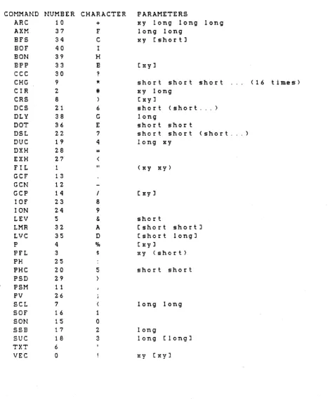
VectorScan 512 24 Appendix 1
APPENDIX 1 - COMMAND SUMMARY
COMMAND ARC AXM BFB BPP
cec
CHGerR
CRSDes
DOT DSL DUC DXH EXH FIL GCF GeN GCP IOF ION LEV LMR LVC P PH PV PFL PHC PSD PSMseL
SOF SON SSBsue
TXT VECx y r al a2 amask xmask
x y 1 1 I 1
xzy xzy xzy. newchar
10 11 12 13
x y r x y
cl c2 c3 c4 on length
s# 10 11 12 13 start# x y
x y
1
s 0
reg# value
x
yx y (amask) type scans d(string>d d(string>d
x y
start
start# <data> d(string>d xl yl x2 y2
FUNCTION
Draw arc AND/XOR mode
Binary f i l l screen Binary point plot
Change Control Character Change levels
Draw circle
Post ion text cursor Define color sequence Dotted line
Define scan levels Draw user character Disable XON/XOFF Enable XON/XOFF Fill screen
Graphics cursor off Graphics cursor on
Position graphics cursor Interlace off
Interlace on Set plot level Load map register Load Video Controller Plot point
Print Horizontal Print Vertical Polygon f i l l Print hard copy Print string direct Printer spooler mode Scale character
Synchronous mode off Synchronous mode on Set screen bottom Set user character Enter text
Draw vector
SECTION 4.4.5 4.4.36 4.4.32 4.4.31 4.4.37 4.4.9 4.4.6 4 .4. 15 4 . 4 . 19 4.4.35 4 .4.18 4.4.26 4.4.28 4.4.27 4.4.7
4 .4. 11
4 .4. 10 4 . 4 . 12 4.4.24 4.4.23 4.4.2 4.4.30 4.4.38 4.4.3 4.4.33 4.4.34 4.4.8 4 .4. 17 4.4.29 4 . 4 .16
4 . 4 . 14
VectorScan 512 25 Appendix 2
APPENDIX 2 - ACCESS TO COMMUNICATION JUMPERS
REMOVE POVER CORD
To access the communication control jumpers:
1.
*****************
REMOVE THE POVER CORD!!!******************
2. Remove all other cables from the VectorScan 3. Remove four corner screws.
4. Slide rear panel and circuit board away from the chassis.
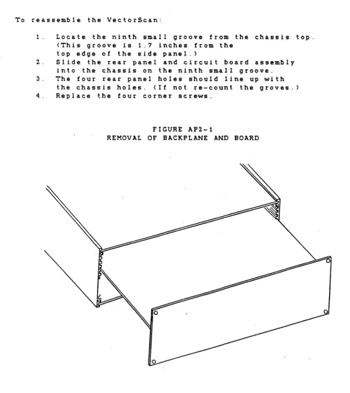
To reassemble the VectorScan:
1. Locate the ninth small groove from the chassis top. (This groove is 1.7 inches from the
top edge of the side panel.>
2. Slide the rear panel and circuit board assembly into the chassis on the ninth small groove. 3. The four rear panel holes should line up with
the chassis holes. (If not re-count the groves. 4. Replace the four corner screws.
FIGURE AP2-1
[image:28.613.46.551.193.760.2]VectorScan 512 26 Appendix 3
APPENDIX 3 - SERIAL CONFIGURATION JUMPERS
The serial channel confiuration may be selected via jumpers located on the VectorScan printed circuit card. To gain access to these, refer to the procedures outlined in appendix 2. Two sets of jumpers are provided one for setting the baud rate and the other for determining the data format. The set of B jumper posts nearest the left side of the circuit board (when veiwed from the back) are for selecting the baud rate. Only one jumper should be installed here. The remaining set of 4 jumper posts, located directly behind the
VectorScan 512 27 Appendix 3
VectorScan circuit board (Top veiw)
Baud rate jumpers - - - + } :
Data format jumpers
---+--}:
I I I I I I I I I I I I I I I I I I I I I I I I I I I I I I I I I I I I I I I I I I I I I I I I
Rear panel ---}
--++++++-++++++-+++++++++-+++--Baud rate jumper selection. JUMPER BAUD RATE
)I( )I( 19200 (Jumper close to MC6850 UART) )I( )I( 9600
)I( )I( 4800 )I( )I( 2400 )I( )I( 1200 )I( )I( 600 )I( )I( 300
)I( )I( 150 (Jumper ~lose to backpanel)
Data format jumper selec.tion
---)1(
)I( (Jumper close to 74LS32)---)1(
)I(---)1(
)I()I( )I( (Jumper close to backpanel)
JUMPER IN/OUT DATA BITS PARITY STOP BITS
I I I 8 ODD 1
I I 0 7 ODD 1
I 0 I 8 EVEN 1
I 0 0 7 EVEN 1
0 I I 8 NONE 1
0 I 0 7 ODD 2
0 0 I 8 NONE 2
VectorScan 512 28
APPENDIX 4 - SUPPORTED GRAPHICS PRINTERS
Printer Type PHC Varable
OKIDATA 83 and 84 1
OKIDATA 82 2
PRISM 80/132 COLOR 3
EPSON MX-80
EPSON MX-100 5
PRISM 132 EXPANDED MODE 6
If your printer is not included in the l i s t of supported printers, then check to see if its graphics structure is the same as one of the printers in the l i s t . If not then please contact Applied Data Systems. Support for printers not contained in the l i s t may have been provided after the printing of this manual.
VectorScan 512 29 Appendix 5
APPENDIX 5 - DOWNLOADABLE CHARACTER FORMAT
A downloadable user shape facility is provided by the
VectorScan. The built in character set includes the printable
ASCII characters which are formed in an 8x8 dot matrix. Sinc.e the
primary application of this device is graphics (not text) the
downloadable characters (shapes) are not specified in a dot
matrix format. Instead, they are specified as a sequence of
vectors. Each vector is specified by either one or two bytes as
described later. The first endpoint of each vector in the shape
is defined as the second endpoint of the last vector plotted for
that shape. The second endpoint of each vector is specified by a
byte (or two bytes) in the shape table and is relative to the
f i r s t endpoint. The very f i r s t vector of a shape uses the
position specified by the Draw User Character ("DUC") command for
i t s first endpoint. Hence the shapes may be placed anywhere in
the display memory. Figure AP5-1 illustrates the above
description. A flag assoc.iated with each byte (or byte pair) in
the shape table specifies whether the vector should be drawn or
the endpoint just updated. This allows disconnected shapes to be
specified. If the vector is drawn, the current plot level will
be used including the highlight mode, if selected. The x-y
character scale ("SCLtI) in effect at the time the shape is drawn
will be used to scale the shape.
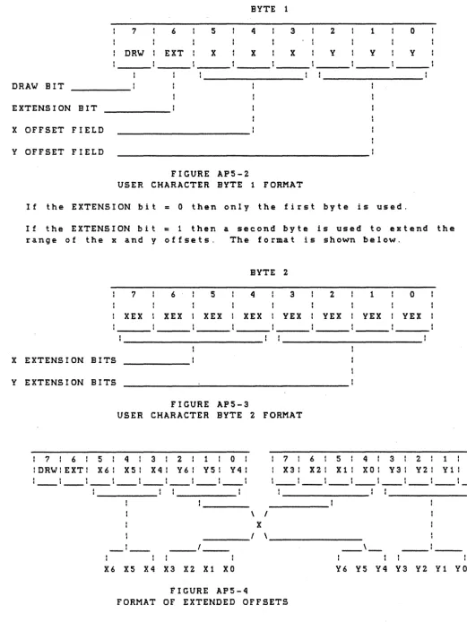
The format of the byte or byte pair whic.h specifies a vector is
shown in figures AP5-2 and AP5-3. First the single byte format
will be described then the two byte format. In the single byte
format, the high order bit (bit 7) is used to specify whether the v e c. tor w i l l bed r awn 0 r not. I f b i t 7 i s " 1" (i e the val u e 0 f the
byte is greater than 127) then the vector will be drawn. The next
bit (bit 6) is the byte extension bit and specifies whether the
two byte format is being used or not. For the one byte format,
bit 6 is "0". Bits 3,4, and 5 specify the x offset of the
vector's second enpoint and bits 0,1, and 2 specify the y o f f s e t . Both the x and y offsets (in the single byte format) range from -4 to 3 and are represented as 3 bit 2's complement numbers.
The two byte vector specification form&t is used to extend the
range of the endpoint offset. Bit 7 of the f i r s t byte indicates
whether or not the vector should be drawn just as in the one byte
forma t . Bit 6, the ext ens ion bit, wi l I b e a II 1" in the two by t e
format to indicate that another byte will follow. Bits 3,4, and 5
represent the three high order bits of the x offset and bits
4,5,6 and 7 of the second byte represent the four low order bits
of the x offset. Similarly, bits 0,1, and 2 represent the three
high bits of the y offset while bits 0,1,2, and 3 are the four
low bits of the y offset. This format is shown in figure AP5-4.
The x and y offsets, using this format, range from -64 to 63 and
are represented as 7 bit 2's complement numbers.
The number of vectors whic.h specify each shape is variable. A
shape terminates when the next byte in the shape table is zero.
This would correspond to not moving the endpoint and not drawing
[image:32.615.61.537.93.362.2]VectorScan 512 30 Appendix 5
length zero.
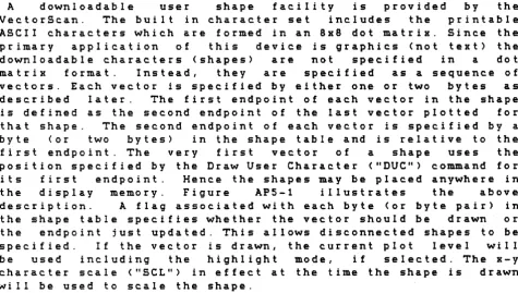
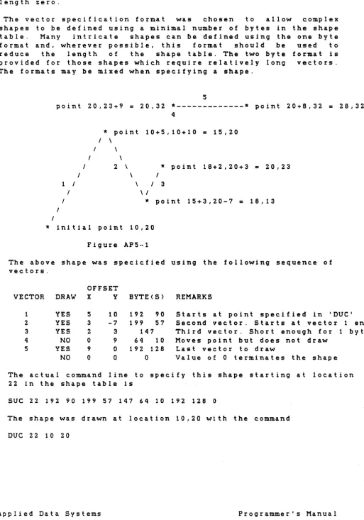
[image:33.615.61.574.60.792.2]The vector specification format was chosen to allow complex shapes to be defined using a minimal number of bytes in the shape table. Many intricate shapes can be defined using the one byte format and, wherever possible, this format should be used to reduce the length of the shape table. The two byte format is provided for those shapes which require relatively long vectors. The formats may be mixed when specifying a shape.
5
point 20,23+9
=
20,32*---*
point 20+8,32=
28,324
I I
1 I I I
/
I
I
*
point 10+5,10+10=
15,20/ \
I \
\
2 \
\
\
*
point 18+2,20+3=
20,23I I 3
\ /
*
point 15+3,20-7=
18,13*
initial point 10,20Figure AP5··1
The above shape was specicfied using the following sequence of vectors.
OFFSET
VECTOR DRAW X Y BYTE(S) REMARKS
1 YES 5 10 192 90 Starts at point specified in 'DUC' 2 YES 3 -7 199 57 Second vector. Starts at vector 1 end 3 YES 2 3 147 Third vector. Short enough for 1 byte
4 NO 0 <} 64 10 Moves point but does not draw
5 YES 9 0 192 128 Last vector to draw
NO 0 0 0 Value of 0 terminates the shape The actual command line to specify this shape starting at location 22 in the shape table is
sue
22 192 90 199 57 147 64 10 192 1280
The shape was drawn at location 10,20 with the command
VectorScan S12 31 Appendix S
BYTE 1
7 6 S 4 3 2 1
o
DRW EXT X X X Y Y Y
DRAW BIT
EXTENSION BIT
X OFFSET FIELD
Y OFFSET FIELD
FIGURE APS-2
USER CHARACTER BYTE 1 FORMAT
If the EXTENSION bit = 0 then only the first byte is used.
If the EXTENSION bit
=
1 then a second byte is used to extend the range of the x and y offsets. The format is shown below.BYTE 2
7 6 S 4 3 2 1
o
XEX XEX XEX XEX VEX VEX VEX VEX
X EXTENSION BITS
Y EXTENSION BITS
FIGURE APS-3
USER CHARACTER BYTE 2 FORMAT
: 7 : 6 : S : 4 : 3 : 2 : 1 : 0 :
lDRW1EXT: X6: XS: X4: Y6: Y51 Y4:
: 7 : 6 : S : 4 : 3 : 2 : 1 : 0 :
: X3: X2: Xl: XO: Y3: Y2: Yl: YO:
\ I
X
---,
,---,
X6 XS X4 X3 X2 Xl XO
FIGURE APS-4
FORMAT OF EXTENDED OFFSETS
[image:34.617.54.576.51.746.2]VectorScan 512 32 Appendix 6
APPENDIX 6 - CONTROL COMMAND SUMMARY
@A TERMINAL ENABLE
This command enables the serial data stream from the computer through the VectorScan to the terminal. This is a power on default mode. If the data stream is already enabled it will remain enabled.
@B TERMINAL DISABLE
This command will inhibit the data stream from the computer through the VectorScan to the terminal. In this manner graphic drawing command can be prevented from being displayed on the user terminal.
@C VECTORSCAN ENABLE
This command will cause the VectorScan to evalualte the incoming data as graphics commands. Data will be scanned until an @D command is recieved.
@D VECTORSCAN DISABLE
This command will inhibit graphics command execution."@" commands will continue to be decoded and processed. This is a power on default mode.
@E ECHO ENABLE
This command will echo all characters back to the computer connector. When echo is enabled, errors in graphic commands will result in question marks being sent to the computer port. This mode is very useful since it allows the VectorScan to be used with a simple RS-232 terminal. (Note that the terminal must be connected to the computer connector through a DCE-DTE swap cable.)
@F ECHO DISABLE
VectorScan 512 33 Appendix 6
@R RESET THE VECTORSCAN
[image:36.615.62.567.100.767.2]1 2
\
\ 20
\
VectorScan 34 Appendix 7
APPENDIX 7- CONNECTOR PINOUTS
This appendix lists the pinouts of the four "0" connectors on the VectorScan. The four connectors are labeled "TERMINAL" I "COMPUTER" I "PRINTER" I and "COLOR VIDEO". The
pin numbering for the three types of connectors is shown below.
9 pin "0" connec.tor pin numbering
5 4 3 2 1
\ I
\ 9 8 7 6 1
\ I
25 pin "0" COMPUTER connector pin numbering
1 2 3 4 5 6 7 8 9 10 11 12 13
\ 1
\ 14 15 16 17 18 19 20 21 22 23 24 25 I
\ I
25 pin "Oil TERMINAL connector pin numbering
13 12 1 1 10 9 8 7 6 5 4 3 2 1 \
\ 25 24 23 22 21 10 19 18 1 7 16 15 14 1
\ I
37 pin liD" connector pin numbering
3 4 5 6 7 8 9 10 1 1 12 13 14 15 16 17
21 22 23 24 25 26 27 28 29 30 31 32 33 34 35
18 19
1
VectorScan 35 Appendix 7
Color video output connecto"r pinouts
PIN SIGNAL 1 GROUND 2 GROUND 3 RED (OUT) 4 GREEN (OUT) 5 BLUE (OUT)
PIN SIGNAL
6 INTENSITY (OUT) 7 NOT CONNECTED
8 HO,R I ZONTAL SYNC (OUT) 9 VERTICAL SYNC (OUT)
PIN SIGNAL
Printer output connector pinouts
PIN SIGNAL 1 {DATA STROBE (OUT)
2 DATA BIT 1 (LSB) (OUT) 3 DATA BIT 2 (OUT)
4 DATA BIT 3 (OUT) 5 DATA BIT 4 (OUT) 6 DATA BIT 5 (OUT) 7 DATA BIT 6 (OUT) 8 DATA BIT 7 (OUT)
9 DATA BIT 8 (MSB) (OUT) 10 {ACKNOWLEDGE (IN)
11 BUSY (IN) 12 NOT USED 13 NOT USED
14 SIGNAL GROUND 15 NOT USED
16 NOT USED
17 CHASSIS GROUND 18 NOT USED
19 NOT USED
20 SIGNAL GROUND 21 SIGNAL GROUND 22 SIGNAL GROUND 23 SIGNAL GROUND 24 SIGNAL GROUND 25 SIGNAL GROUND 26 SIGNAL GROUND 27 SIGNAL GROUND 28 SIGNAL GROUND 29 SIGNAL GROUND 30 SIGNAL GROUND 31 NOT USED
32 NOT USED
33 SIGNAL GROUND 34 NOT USED
35 NOT USED 36 NOT USED 37 NOT USED
Computer connector pinouts
PIN SIGNAL
1 PROTECTIVE GROUND 2 TRANSMIT DATA (OUT) 3 RECEIVE DATA (IN)
4 CONNECTED TO TERMINAL PIN 4 5 CONNECTED TO TERMINAL PIN 5 6 CONNECTED TO TERMINAL PIN 6 7 SIGNAL GROUND
8 CONNECTED TO TERMINAL PIN 8 9 CONNECTED TO TERMINAL PIN 9 10 CONNECTED TO TERMINAL PIN 10 11 CONNECTED TO TERMINAL PIN 11 12 CONNECTED TO TERMINAL PIN 12 13 CONNECTED TO TERMINAL PIN 13
PIN SIGNAL
VectorScan 36 Appendix 7
Terminal connector pinouts
PIN SIGNAL PIN SIGNAL
1 PROTECTIVE GROUND 14 CONNECTED TO COMPUTER PIN 1 4 2 TERMINAL TRANSMIT DATA ( IN) 15 CONNECTED TO COMPUTER PIN 15
3 TERMINAL RECEIVE DATA (OUT) 16 CONNECTED TO COMPUTER PIN 16 4 CONNECTED TO COMPUTER PIN 4 17 CONNECTED TO COMPUTER PIN 17 5 CONNECTED TO COMPUTER PIN 5 18 CONNECTED TO COMPUTER PIN 18 6 CONNECTED TO COMPUTER PIN 6 19 CONNECTED TO COMPUTER PIN 19
7 SIGNAL GROUND 20 DATA TERMINAL READY ( IN)