Ergonomics Analysis
Thesis submitted in accordance with the requirements of
the University of Liverpool for the degree of Doctor in Philosophy
by
Ziyun Ding
In manufacturing industry, although automation techniques have been employed widely, many tasks still require the flexibility and intelligence of human operators, especially in the product assembly process. Insufficient industrial ergonomics in the assembly process will cause the health problems and quality and productivity losses, ultimately increase costs of the final product. The purpose of this thesis is to integrate ergonomic considerations into the manual assembly process modelling and simulation in order to provide product/process design changes before their physical prototyping.
In this research, a state-of-the-art commercial software tool - DELMIA - is adopted for the ergonomics simulation and analysis. Associated with its capabilities for the ergonomics solution, a series of human related issues in the manual assembly process is simulated and studied in order to demonstrate the benefits of a virtual assembly approach to the product deign, workplace deign, time and energy saving.
Due to the poor repeatability and reproducibility of digital human postures in DELMIA manipulation, a posture prediction method is developed aiming at a practical and precise ergonomics analysis. A 10-degrees-of-freedom, 4-control-points digital human model concerned with assembly features and human diversity is established. The multi-objective optimisation method is applied to assembly posture prediction in which optimisation objectives (i.e. joint discomfort and metabolic energy expenditure) and constraints corresponding to manual assembly tasks are proposed and formulated. Following the verification of the posture prediction method, a series of posture strategies under different assembly conditions are investigated towards more comfortable and energy-efficient assembly postures.
Thus far, the consideration on assembly operators in assembly sequencing is insufficient though it plays a key role in the integrative product and process design. In this research, the use of new ergonomic constraints into assembly sequencing optimisation is proposed. Feasible assembly sequences are generated and evaluated based on the product geometry, assembly workstation layout, operator characteristics and working posture. A new Liverpool Assembly Sequence Planning System (LASP) is developed to achieve the integration by applying two evaluation criteria, i.e. visibility criterion, accessibility criterion or both. With LASP, possible design faults with respect to restricted visibility and obstructed accessibility is obtainable during the early design stage. Meanwhile,
First, I would like to express my deepest gratitude and admiration to my supervisor, Professor Bernard Hon for giving me the opportunity to undertake my PhD in the University of Liverpool and allowing me the space and freedom to explore new knowledge. I am grateful for his substantial amount of effort and guidance over the past four years. I would also like to express my sincerely gratitude to Dr. Tim Short for his continuous encouragements and invaluable feedbacks.
I feel honoured to have had a learning and working experience in the Virtual Engineering Centre in the Daresbury Laboratory, Warrington. Many thanks to Dr. Antony Robotham for his support, allowing me to utilise a series of VR facilities in the VEC to accomplish my research. I am especially grateful to Dr. Fei Shao, for his generous sharing of knowledge and experience, assisting me to carry out experiments and realising my initial idea.
I would like to acknowledge the Chinese scholarship Council (CSC) of China, for the financial support that made this thesis possible.
Finally, a special thanks to my parents who have been an incredible source of support. I can never express how lucky I feel to be their daughter so I can pursue my dream so determinedly. Also, many thanks to my husband Dr. Zhangming Wu for his understanding and support mentally and academically.
Abstract i
Acknowledgements iii
List of Figures vii
List of Tables xi
Abbreviations xiii
Notations xiv
1 Introduction 1
1.1 Aim and Objectives . . . 4
1.2 Research Overview . . . 5
1.3 Structure of Thesis . . . 6
2 Literature Review 8 2.1 Introduction . . . 8
2.2 Ergonomic Simulation of Assembly Process . . . 10
2.2.1 Manual Assembly . . . 10
2.2.2 Ergonomic Consideration . . . 11
2.2.3 Ergonomics Simulation in the Virtual Environment . . . 12
2.3 Human Posture Modelling in Manual Tasks . . . 16
2.3.1 Digital Human Modelling . . . 16
2.3.2 Human Posture Prediction . . . 18
2.3.3 Human Performance Measures . . . 20
2.3.4 Human Task Evaluation . . . 25
2.4 Virtual Assembly Process Planning . . . 27
2.4.1 Assembly Sequence Planning . . . 27
2.4.2 Assembly Sequence Planning System . . . 27
2.4.3 Assembly Sequence Planning Criteria . . . 31
3 Manual Assembly Process Simulation 33 3.1 Introduction . . . 33
3.4 Virtual Assembly Environment . . . 37
3.5 Ergonomics Analysis . . . 40
3.5.1 Posture Analysis . . . 40
3.5.2 Cycle Time Analysis . . . 40
3.5.3 Energy Expenditure Analysis . . . 42
3.5.4 Reach Analysis . . . 42
3.5.5 Vision Analysis . . . 43
3.5.6 Clearance Analysis . . . 44
3.6 Case Study: A Comparison Study of Product Assemblability . . . . 45
3.6.1 Method and Materials . . . 46
3.6.2 Development of Virtual Assembly Environment . . . 46
3.6.3 Results . . . 48
3.6.4 Discussion . . . 53
3.7 Case Study: Ergonomic Design of Manual Assembly Workplace . . 56
3.7.1 General Workplace Design Procedure . . . 57
3.7.2 Method and Materials . . . 57
3.7.3 Results . . . 62
3.7.4 Discussions . . . 65
3.8 Conclusions . . . 69
4 Posture Analysis of Manual Assembly 71 4.1 Introduction . . . 71
4.2 Digital Human Modelling . . . 72
4.2.1 Model Simplifications . . . 72
4.2.2 A 10-DOF, 4-Control-Points Human Model . . . 73
4.2.3 Human Diversity . . . 81
4.3 Multi-Objective Optimisation Method for Posture Prediction . . . . 83
4.3.1 Overview of Multi-Objective Optimisation . . . 83
4.3.2 Optimisation Objectives . . . 85
4.3.3 Optimisation Algorithm . . . 93
4.3.4 Model Verification . . . 96
4.4 Task-Based Posture Analysis . . . 105
4.5 Results . . . 107
4.5.1 Optimum Posture Analysis . . . 107
4.5.2 Effect of Object Height . . . 108
4.5.3 Effect of Distance to Object . . . 108
4.5.4 Effect of Object Weight . . . 109
4.6 Conclusions . . . 111
5 Ergonomic Evaluation of Assembly Sequence 113 5.1 Introduction . . . 113
5.2 Type of Assembly Sequences . . . 114
5.2.3 Linearity . . . 115
5.3 Assembly Planning Description . . . 116
5.3.1 Local Motion . . . 116
5.3.2 Global Motion . . . 116
5.3.3 Sweeping . . . 117
5.4 Representations of Assembly Sequences . . . 117
5.4.1 State Graphs . . . 118
5.4.2 AND/OR Graphs . . . 119
5.5 Assumptions . . . 120
5.6 Generation of all Feasible Assembly Sequences . . . 121
5.7 Criteria of Manual Assembly Sequence Evaluation . . . 123
5.7.1 Visibility . . . 123
5.7.2 Accessibility . . . 135
5.7.3 Combination of Visibility and Accessibility . . . 142
5.8 A Manual Assembly Sequence Planning System . . . 142
5.8.1 System Description . . . 142
5.8.2 System Input . . . 144
5.8.3 Case Study . . . 145
5.8.4 Discussion . . . 151
5.9 Conclusions . . . 152
6 Conclusions and Future Research 154 6.1 Conclusions . . . 154
6.2 Future Research . . . 157
Appendix A Anatomical and Anthropometric Terminology 160 A.1 Anatomical Position . . . 160
A.2 Reference Planes . . . 161
A.3 Anatomical Relationship . . . 161
A.4 Joint Movements . . . 163
Appendix B MATLAB Optimization Routines 166 B.1 Constraints . . . 166
B.2 Multi-Objective . . . 169
B.3 SQP Algorithm . . . 172
Appendix C Optimum Assembly Postures 174
1.1 Market values of enterprises [2]. . . 1
1.2 Consequences of the poor product/process design from the ergonomic viewpoint. . . 3
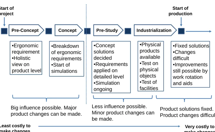
1.3 Description of ergonomic influence during the product development process [8]. . . 3
1.4 The thesis structure. . . 6
2.1 The literature review structure. . . 9
2.2 Reasons for reduction of automation [1]. . . 11
2.3 Examples of commercial digital human models. . . 17
2.4 The lower arm posture score calculation [59]. . . 23
2.5 Constraints for lifting tasks [78]. . . 26
2.6 An example of the liaison graph [10]. (Part A is a screw that fastens part B to part C) . . . 28
3.1 The interface for creating standard manikins. . . 35
3.2 Anthropometry tools in MHM. . . 36
3.3 An example of the Gantt chart in the human task simulation. . . 37
3.4 The angles editing panel [99]. . . 38
3.5 A PPR environment in DELMIA. . . 39
3.6 Steps of the assembly process simulation. . . 39
3.7 Colours representing intermediate scores [99]. . . 41
3.8 An example of RULA analysis. . . 41
3.9 An ideal reach envelope [99]. . . 43
3.10 A 90% reach envelope [99]. . . 44
3.11 A binocular vision window of a manikin [102]. . . 44
3.12 A head clearance analysis [102]. . . 45
3.13 Formula student car – ULM005. . . 46
3.14 The simulation flow chart of the FS car assembly process. . . 47
3.15 The virtual assembly environment of the FS car. . . 48
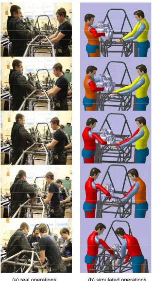
3.16 Operations in the engine assembly process. . . 49
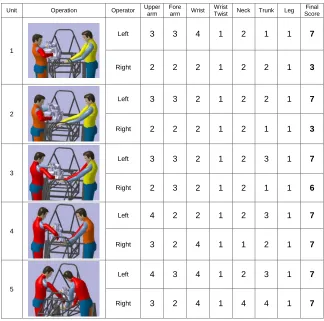
3.17 RULA scores of operations in the engine assembly process. . . 50
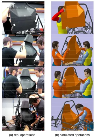
3.18 Operations in the firewall assembly process. . . 52
3.19 RULA scores of operations in the firewall assembly process. . . 53
3.20 Task of the plenum assembly. . . 54
3.21 Task of the bodywork assembly. . . 55
3.22 The blower model for manual assembly [114]. . . 58
3.25 The alternative workplace layout designs. . . 61
3.26 The alternative part location designs. . . 62
3.27 The simulation flow chart of workplace design. . . 63
3.28 Simulation results. . . 64
3.29 ANOM diagram of process cycle time. . . 64
3.30 ANOM diagram of energy expenditure. . . 64
3.31 The optimum workplace design. . . 66
3.32 Reach analysis in the assembly process simulation. . . 66
3.33 Unacceptable postures in level 1 of work bench height. . . 67
3.34 Unacceptable postures in level 3 of work bench height. . . 68
4.1 A 10-DOF human model. . . 73
4.2 Parameters for the D-H method. . . 75
4.3 4 control points in the human model. . . 77
4.4 The position of assembly object. . . 77
4.5 The locations of centres of mass in the body segments in the sagittal plane [128]. . . 82
4.6 The neutral position of the digital human. . . 87
4.7 Hip discomfort measure. . . 87
4.8 Knee discomfort measure. . . 88
4.9 Static force modelling on the sagittal plane. . . 90
4.10 The procedure for posture prediction via the SQP method. . . 95
4.11 Illustration of locations of subjects and objects in the experiment. . . . 97
4.12 The stereo vision system. . . 98
4.13 A suit configuration tool. . . 98
4.14 10 props for tracking objects. . . 99
4.15 The location of ten props. . . 99
4.16 A schematic plot of the experiment procedure. . . 100
4.17 Qualitative comparative results for target 1. . . 101
4.18 Qualitative comparative results for target 2. . . 101
4.19 Qualitative comparative results for target 3. . . 102
4.20 Qualitative comparative results for target 4. . . 102
4.21 Regression plot of joint rotation variables . . . 103
4.22 The range of mean differences from q5 to q10. . . 105
4.23 Illustration of the visual demands. . . 106
4.24 Optimum hip displacement for different operators. . . 108
4.27 The effect of object weight. . . 110
5.1 An example of no monotone binary assembly sequence [148]. . . 115
5.2 An example of no linear assembly sequence [148]. . . 116
5.3 An example of sweeping [88]. . . 117
5.4 A simple product and its liaison diagram [10]. . . 119
5.5 The liaison sequence diagram for the example product [10]. . . 119
5.6 An example of the AND/OR graph [10]. . . 120
5.7 The procedure for generating feasible assembly/disassembly sequences. 121 5.8 Properties of digital operator for the visibility evaluation. . . 124
5.9 Minimum entities required in a viewing system. . . 125
5.10 The determination of a view coordinate system in the assembly process.126 5.11 A comparison between the parallel projection and the perspective projection. . . 127
5.12 Deriving a perspective transformation. . . 127
5.13 A product for the visibility evaluation. . . 129
5.14 Weiler-Atherton clipping. . . 133
5.15 Back-face elimination. . . 134
5.16 The flowchart for the visible area determination. . . 135
5.17 The procedure of assembly sequence selection based on the visibility criterion. . . 136
5.18 An example of hand manipulation space. . . 136
5.19 The flowchart to calculate the amount of approach directions. . . 138
5.20 An illustration of the approach direction. . . 140
5.21 Three types of hand grasp. . . 141
5.22 An example of the accessibility criterion application. . . 141
5.23 The framework of LASP system. . . 142
5.24 A typical interface of LASP. . . 143
5.25 The CAD model of air conditioner [158]. . . 145
5.26 The disassembly environment of the air conditioner. . . 146
5.27 AND/OR graph of air conditioner assembly. . . 147
5.28 AND/OR graph of air condition assembly with the visibility criterion. 148 5.29 AND/OR graph of air condition assembly with the accessibility criterion. . . 149
5.30 AND/OR graph of air condition assembly with the visibility and accessibility criteria. . . 150
A.3 Terms of relationship. . . 162
A.4 Extension and flexion of (a) the wrist; (b) the elbow; (c) the shoulder. 163 A.5 Abduction and adduction of (a) the wrist; (b) the shoulder. . . 164
A.6 The elbow rotation. . . 164
A.7 (a) Pronation and (b) supination of the shoulder. . . 165
C.1 Optimum assembly postures for 5th percentile operators. . . 174
C.2 Optimum assembly postures for 25th percentile operators. . . 175
C.3 Optimum assembly postures for 50th percentile operators. . . 175
C.4 Optimum assembly postures for 75th percentile operators. . . 176
C.5 Optimum assembly postures for 95th percentile operators. . . 176
2.1 A brief history of ergonomics [15] . . . 12
2.2 DELMIA vs. Jack. . . 13
2.3 OWAS coding system [19] . . . 21
2.4 PLIBEL questions relating to the low extremity [60] . . . 22
2.5 Stress rating response and their explanations in postural checklist [61] 23 2.6 A summary of literature on the development of assembly planning systems . . . 30
3.1 GARG equations . . . 42
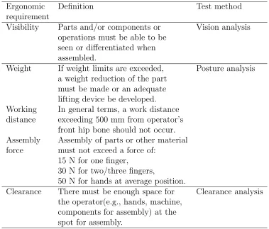
3.2 Common ergonomic requirements in automatic industry [103] . . . 47
3.3 Weights of the assembly part or component . . . 58
3.4 The assembly process of the blower . . . 59
3.5 Design factors and their levels . . . 60
3.6 Factor levels for each simulation . . . 63
3.7 Range analysis of process cycle time (s) . . . 65
3.8 Range analysis of energy expenditure (kcal) . . . 65
3.9 Optimum factor values . . . 65
3.10 Walking distance of workplace layout . . . 69
4.1 List of body dimensions and their definitions . . . 74
4.2 10 degrees of freedom and their descriptions . . . 74
4.3 D-H parameters table between the foot and the hip . . . 78
4.4 D-H parameters table between the shoulder and the hand . . . 79
4.5 Anthropometric data for British male, aged 19 to 65 years. (all dimensions in millimetres, except for body weight, given in kilograms) 81 4.6 Masses of body segments as a percentage of the whole body mass [130] 82 4.7 Parameters in the joint discomfort model . . . 86
4.8 Joint weights for discomfort . . . 86
4.9 Joint neutral position and movement ranges (degree) . . . 86
4.10 Joint torque limit [137] . . . 89
4.11 Calculating formulae of θj(j = 1,2, ...,6) . . . 91
4.12 Subject summary statistics . . . 96
4.13 Target Objects in the experiment . . . 97
4.14 Wilcoxon Signed-Rank tests of joint variables . . . 104
5.1 Anthropometric variables . . . 123
5.2 Optimum assembly sequences of air conditioner . . . 151
ANOM Analysis of Means BMR Basal Metabolic Rate DFA Design for Assembly DHM Digital Human Modelling DOF Degree of Freedom
FS Formula Student
LASP Liverpool Assembly Sequence Planning MAA Human Activity Analysis
MHB Human Builder
MHM Human Measurements Editor MHP Human Posture Analysis MHT Human Task Simulation MOO Multi-Objective Optimisation MTM Methods Time Measurement
NIOSH National Institute for Occupational Safety and Health OSHA Occupational Safety and Health Administration OWAS Ovako Working Posture Analysis System
PLM Product Lifecycle Management PPR Product, Process and Resource RTI Real-Time Interaction
RULA Rapid Upper Limb Assessment SQP Sequential Quadratic Programming WMSD Work-related Musculoskeletal Disorder VR Virtual Reality
t Cycle time
th Handling time
ti Insertion time
E Energy expenditure
BW Body weight
S Gender
F Lifting frequency
L Load weight
s Sample standard deviation
xp pth percentile value of the variable x
zp Standard normal vale correspoing to the pth percetile value of x
qi Current position of joint i
qiU Upper limit of joint i qiL Lower limit of joint i qiN Neutral position of joint i QUi Penalty term of upper limits
QLi Penalty term of lower limits
γi Weighting value of joint i
˙
E Muscle energy expenditure rate ˙
EW Muscle mechanical power
˙
EM Muscle maintenance heat rate
˙
ES Muscle shortening heat rate
˙
EB Basal metabolic rate
τi Joint torque
˙
qi Joint velocity
ξi Coefficient of the maintenance heat rate
LH Magnitude of the workload held on the hands
f(q) A vector of objective functions
fi(q) The ith objective function
h(q) Equality constraints
wi Weight of the ith objective function
Introduction
The human element is the most valuable resource a company has in building up core competence and business excellence [1]. Skilled operators are essential for efficient innovative technological and logistical processes. As a so-called process owner, operators take responsibilities to optimise productivity and quality and minimise production costs. The fact is described by the changing value components to a company as shown in Figure 1.1 [2]. Nowadays, 70% of a company’s market value is made up of the value of intellectual property (IP), which is represented by its employees. Despite the significance of the human element, countless organisations in a variety of industries are facing the same problem: the human element is not being considered early or thoroughly enough in the design, assembly and maintenance stage of products. More importantly, this is having a devastating impact on cost, time to market, quality and safety.
80% Book Value
20% IP
Market Value 1978
30% BV
70% IP
[image:17.596.224.413.533.636.2]Market Value today
Figure 1.1: Market values of enterprises [2].
In manufacturing industry, although automation techniques have been employed widely, many tasks are still accomplished manually especially in the product assembly process. Assembly is the most relevant area of human involvements for several major reasons. For instance, market factor and
competition increase the number of product variants and lead to a decrease in batch size. Human operators are capable of mastering different variants in assembly to save expensive investments in automation and to increase the flexibility and reconfigurability of production systems. Deficient industrial ergonomics is a major reason for sick leave and work injuries in manufacturing industry [3–5]. Replacement of staff and rehabilitation consume considerable resources in manufacturing companies and cost a huge amount of money for companies and societies. According to the US Occupational Safety and Health Administration (OSHA), work-related musculoskeletal disorders (WMSDs) account for more than US$15-$20 billion in workers’ compensation costs; the total costs, direct and indirect, may be close to US$60 billion each year. High staff turnover and sick leave cause production disturbances and inefficiencies and result in productivity losses. Moreover, several studies have identified a relationship between ergonomically problematic tasks and quality deficiencies to the extent that around 30-50% of all quality flaws are related to or directly due to ergonomics problems [6]. Investigations from manufacturing companies further reveal a correlation that 60-70% of WMSDs are caused by the product design and 30-40% by the assembly process [7]. Product design-related issues could be, for example, hand access problems due to bad clearances, or high assembly force due to poor fittings. Assembly process-related issues include poor workplace design (e.g., bad visibility, awkward workplace layouts and unsuitable working heights); poor work method design (e.g., ineffective motions and hazardous working postures); and poor assembly process planning. The relationship between the poor product/process design and its negative effect on health, productivity, quality and cost is summarised in Figure 1.2.
Product & Process Impact on Health, Productivity, Quality and Cost
Poor product design (60-70%)
Poor process design: workplace design work method design
process planning (30 -40%) Poor ergonomics & assemblability Health effects: Musculoskeletal disorders Sick leave Rehabilitation Staff turnover Productivity losses:
From minor production disturbances to standstill
Quality losses:
Repair and scrap Brand image reduction
Increased costs Increased costs
[image:19.596.115.516.89.346.2]Increased total cost of the final product Increased costs
Figure 1.2: Consequences of the poor product/process design from the
ergonomic viewpoint.
Pre-Concept Concept Pre-Study Industrialization
•Ergonomic requirement •Holistic view on product level •Breakdown of ergonomic requirements •Start of simulations •Concept solutions decided •Requirements applied on detailed level •Simulation ongoing •Physical products available •Test on physical objects •Test of facilities •Fixed solutions •Changes difficult •Improvements still possible by work rotation and aids Start of project Start of production
Least costly to
make changes make changes Very costly to
Big influence possible. Major product changes can be made.
Less influence possible. Minor product changes can be made.
Product solutions fixed. Product changes difficult.
Figure 1.3: Description of ergonomic influence during the product
[image:19.596.133.497.460.683.2]In recent years, the advance of a series of powerful computer simulation tools has made it possible to be executed on modern desktop computers instead of expensive workstations and mainframes, thus facilitating the simulation applications in manufacturing industry. New computer simulation technologies encompass all aspects of product development (including manufacture, maintenance, product life cycle, ergonomics, etc.) with the greatest potential impact during the early stages of product design. They empower manufacturing industry with a faster and more powerful decision making process. Four immediate benefit of the computer simulation are given as follows [9]:
1. While in the design stage, designers may virtually eliminate the time and costs of expensive tooling rework or design changes.
2. Simulation also eliminates costly and time-consuming physical mockups.
3. Manufacturing engineers reduce time-to-market by visualising and validating processes digitally before committing resources and purchasing or modifying equipments and tooling after simulation is validated. Engineers may use the product and process models for training, maintenance, and documentation.
4. Ergonomics, anthropometry and physiology issues can be analysed and addressed while the system is still in the design stage.
Ergonomics simulation is used to perform ergonomics analysis for product/process validation. The main purpose of an ergonomics simulation is to apply biomechanical models and data to assess the acceptability of physical workload. The design of product and process may be changed in order to improve ergonomic conditions in manual assembly and to promote overall productivity performances.
1.1
Aim and Objectives
The aim of this thesis is to integrate ergonomic considerations into assembly process modelling and simulation in order to provide product/process design changes before their physical prototyping.
The primary research objectives of this thesis are as follows:
• to develop an assembly posture prediction method for the practical and precise ergonomics analysis in the assembly process;
• to propose assembly posture strategies in terms of task constraints, human diversity and human performances;
• to propose new ergonomic constraints for manual assembly sequence evaluation;
• to develop an assembly sequence planning system integrated with ergonomic constraints.
1.2
Research Overview
The research in this thesis involves multidisciplinary knowledge comprising different expertise for the ergonomics simulation and analysis; human posture modelling and prediction; computer aided assembly process planning. The main research deliverable in the thesis is to apply and develop novel computer modelling and simulation technologies towards the complete and correct ergonomics analysis in the manual assembly process.
First, a state-of-the-art commercial software tool is adopted for the ergonomics simulation and analysis. Associated with its capabilities in the ergonomics solution, a series of human related issues in the manual assembly process is simulated and studied in order to demonstrate the benefits of a virtual assembly approach to the product deign, workplace deign, time and energy saving.
used to conduct a more accurate posture analysis and investigate posture strategies under different assembly conditions.
In the manual assembly process, the choice of assembly sequences is important due to its significant influence on the product quality, assembly efficiency and operator performances. A well-designed assembly sequence, for example, will be easy for operators to perform and conversely, a poorly designed assembly sequence which includes awkward manoeuvres and whose execution will injure or fatigue operators gives rise to product quality losses. Therefore, the advantages of incorporating assembly operators in a proper assembly sequencing are very exciting. Consideration of high-level ergonomic issues at the product design stage eliminates possible design faults which lead to poor assembly postures, limited visibility and hand accessibility of assembly objects. More importantly, operator’s health and safety can be improved, facilitating the improvement of product quality and productivity, reducing product cost and time to market in the long term.
1.3
Structure of Thesis
The remainder of the thesis consists of five chapters, including one chapter of literature review, three chapters of original research work, and one chapter of conclusions. Figure 1.4 shows the thesis structure.
Chapter 2 Literature Review
Chapter 3 Manual Assembly Process Simulation
Chapter 4 Posture Analysis of
Manual Assembly
Chapter 5 Ergonomic Evaluation of
Assembly Sequence
Chapter 6 Conclusion and Future Research
Figure 1.4: The thesis structure.
disadvantages of previous research are reviewed and discussed.
Chapter 3 proposes a virtual assembly approach for the product assemblability analysis and the workplace design. First, a visual assembly environment is created where the ergonomics simulation and analysis is carried out utilising the commercial software tool – DELMIA. By studying two cases in the virtual environment, the influence of a series of product/process related factors and their combination to human performances in manual assembly tasks is investigated. Finally, the behaviour of DELMIA in the ergonomics simulation and analysis is evaluated.
Chapter 4 presents an optimisation-based posture prediction method in order to simulate and analyse manual assembly tasks with higher actuality and accuracy. At first, a 10-degrees-of-freedom (DOF), 4-control-points digital human model taking assembly features and human diversity into account is proposed. Next, the multi-objective optimisation method is applied to predict assembly postures and its efficiency and accuracy can be verified via experimental data. Finally, by incorporating specific constraints identified by the assembly task, posture strategies under different assembly conditions are investigated.
Chapter 5 proposes an integration of new ergonomic constraints in the objective evaluation of assembly sequencing for manual assembly tasks. Firstly, feasible assembly sequences are generated and evaluated based on the product geometry, assembly workstation layout, operator characteristics and posture. Subsequently, a new Liverpool Assembly Sequence Planning System (LASP) is developed to achieve this integration by applying two different evaluation criteria, i.e. visibility criterion, accessibility criterion or both.
Literature Review
2.1
Introduction
Research presented in this thesis mainly consists of three parts: simulation of manual assembly process, assembly posture prediction and analysis, and ergonomics evaluation of assembly sequences. The reviewed work thus covers a wide range of areas. In this chapter, the literature related to these areas would be reviewed respectively.
In Section 2.2, the characteristics of manual assembly in manufacturing industry are summarised. Latterly, the definition of ergonomics as well as its developments and applications in manufacturing industry are introduced. Finally, a review on traditional and advanced ergonomics simulation technologies is given. The review of Section 2.2 leads to the research work of manual assembly process simulation in Chapter 3.
Human posture modelling is crucial to the realistic and accurate ergonomics simulation and analysis. In Section 2.3.1, a review on digital human modelling tools is carried out, including academic modelling tools and commercial modelling tools, which points at one limitation of them, i.e. the incapability in predicting complex human postures. In Section 2.3.2, general approaches to solve the posture prediction problem are presented. Human performance measures are often taken as the objective functions of an optimisation-based posture prediction problem and those relating to this investigation are introduced and discussed in Section 2.3.3. Postures should satisfy certain constraints which are proposed by different manual tasks, therefore in Section 2.3.4 a review is given on task-based posture prediction and analysis. The review of Section 2.3 is the
basis of the original research work in Chapter 4.
In Section 2.4, the definition and significance of assembly planning and assembly sequence planning are identified first. General approaches to generate assembly sequences and their applications in some typical assembly sequencing systems are presented later. Finally, evaluation criteria for assembly sequence optimisation are described. The literature review of the current assembly sequencing systems exposed their common limitation, i.e. considerations on human operators (including their anthropometry characteristics and working postures) are deficient. This finding will be taken into account in Chapter 5.
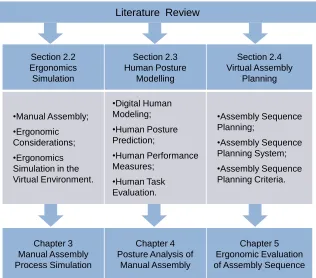
Figure 2.1 illustrates the structure of the literature review and the correspondence of each section to the original research in the thesis.
Literature Review
Section 2.2 Ergonomics Simulation Section 2.3 Human Posture Modelling Section 2.4 Virtual Assembly Planning •Manual Assembly; •Ergonomic Considerations; •Ergonomics Simulation in the Virtual Environment. •Digital Human Modeling; •Human Posture Prediction; •Human Performance Measures; •Human Task Evaluation. •Assembly Sequence Planning; •Assembly Sequence Planning System; •Assembly Sequence Planning Criteria. Chapter 3 Manual Assembly Process Simulation Chapter 4 Posture Analysis of
Manual Assembly
[image:25.596.158.474.346.624.2]Chapter 5 Ergonomic Evaluation of Assembly Sequence
2.2
Ergonomic Simulation of Assembly Process
2.2.1
Manual Assembly
Assembly is the capstone process in manufacturing which brings together all the upstream processes of design, engineering, manufacturing, and logistics to create an object for desired functions [10]. Until very recently, assembly was accomplished exclusively manually. Automatic assembly systems were designed to perform high volume assembly of simple items in the twentieth century. In the 1970s, interest in robot assembly arose. High hopes were placed on robots combined with vision systems, force and touch sensors, powerful computers and artificial intelligence. Many original equipment manufacturers were even dreaming about a completely robotised assembly system. Through the years, this ideology crashed because of a lot of obstacles and imperfections, such as the technical complexity, high cost of machines and maintenance [11].
14% 25%
39% 41%
57% 65%
0% 10% 20% 30% 40% 50% 60% 70%
shorter product life cycles lower production costs higher product flexibility lower investments higher flexibility of capacity decreasing lot sizes
Figure 2.2: Reasons for reduction of automation [1].
2.2.2
Ergonomic Consideration
Ergonomics can be defined as “ the branch of science that is concerned with the achievement of optimal relationships between workers and their work environment [14]”. It deals with assessments of the human’s capabilities and limitations (biomechanics and anthropometry), work and environmental stress (work physiology and industrial psychology), static and dynamic forces on the human body structure (biomechanics), design simulation and training, and design of workplace and tools (anthropometry and engineering). Therefore, ergonomics draws heavily from many areas of sciences and engineering.
The term ergonomics has its root in Ramazzini’s study of the ill-effects of poor postures and poorly designed tools on the health of workers in the early 1900s. Table 2.1 shows a brief history of ergonomics [15]. The goal of ergonomics is to fit work to individuals, as opposed to fitting individuals to the work. Given a body of scientific knowledge, it aims at developing efficient adaptions of work methods to the individual’s physiological and psychological characteristics. Therefore, the mission of an ergonomist is to identify and alleviate those work stresses which adversely affect the health, safety and efficiency of human operators.
In manufacturing industry, ergonomists use ergonomics principles for the following considerations [14]:
• Design, modification, replacement and maintenance of equipments for enhanced productivity and quality;
Table 2.1: A brief history of ergonomics [15]
Year Ergonomics Social background
1900s Time and motion study Growth of industry 1930s Powered conveyor line Mass production
1940s Human factors World War II
1960s Anthropometry Growth of the consumer market
Biomechanics Space development
1970s Occupational safety and health Occupational safety and health act Labor Unions
1980s Human-computer interaction Computer
LAN (Local Area Network) 1990s Computer-oriented work Personal computing
Internet
2000s - Information revolution
Globalisation industry Knowledge society
• Design and modification of work methods, including automation and task allocation between human operators and machines;
• Controlling physical factors (e.g., temperature, illumination, noise) in workplace for the best productivity and safety of operators.
2.2.3
Ergonomics Simulation in the Virtual Environment
applied.
With the development of computer science, a serious of commercial software tools are available for ergonomics simulation and analysis, furthering a faster and more efficient product/process design. Those tools replace the human operator with an anthropometric articulated representation of a human being, call “manikin” [16]. This technology poses an opportunity to integrate ergonomic considerations into early design stages. Two of the main software tools, DELMIA from Dassault Systemes and Jack from Siemens Tecnomatix have been benchmarked. Table 2.2 shows a comparison between them focusing on features such as the data exchange capability, ergonomic analysis capability and typical applications.
Besides, virtual reality (VR), as an extension of simulation technologies allowing designers to immerse in a simulated environment and perform operations through various input/output devices, has been applied in ergonomics research.
Table 2.2: DELMIA vs. Jack.
Main properties Software
DELMIA Jack
Data Direct CAD interface: Direct CAD interface:
exchange CATIA Unigraphics NX
capability neutral formats: neutral formats:
IGES,DXF, IGES,DXF
STEP,STL STEP,STL
Ergonomic Carry analysis; Fatigue analysis; analysis Lift/lower analysis; Low back analysis; capability Push/pull analysis; Manual material
Reach envelop analysis; handling analysis; Metabolic energy Metabolic energy
expenditure; expenditure; Biomenchanical analysis; NIOSH lifting analysis;
Vision analysis; Static strength prediction; Predetermined time Predetermined time
standards; standards;
Rapid upper limb Rapid upper limb assessment(RULA) assessment(RULA);
Jayaram et al. defines the key elements of VR as “ a) immersion in a 3D environment through stereoscopic viewing, b) a sense of presence in the environment through tracking and representing the user in the environment, c) presentation of information of the sense other than vision, and d) realistic behaviour of all objects in the virtual environment [23].” In a VR system, the ability to visualise realistic behaviour of CAD models and represent complex human interactions facilitates designers to identify assembly-related problems in the conceptual product design state, such as awkward reach angles, insufficient clearance for tooling, and excessive part orientation during assembly, etc. It also supports designers to analyse tooling and fixture requirements for assembly. In addition to visualisation, designers can touch and feel complex CAD models of parts and interact with them using natural and intuitive human motions with the assistance of haptic technology. With the force feedback device, collision and contact forces calculated in real-time can be transmitted to the user by robotic devices, making it possible for him to feel the simulated physical contacts that occur during assembly. These capabilities make VR tool ideal for ergonomics simulations which require frequent and intuitive manual interaction such as assembly method planning.
Rajan et al. developed a Virtual Reality-based environment JIGPRO for the analysis of product assembly and jig design [24]. 3D CAD models of assembly product, jig and a virtual hand were imported into JIGPRO for assembly process simulation and accessibility analysis. The main purpose was to analyse accessibility during assembly and to reduce the risk of musculoskeletal injuries.
Chryssolouris et al. developed an experimental virtual environment for the verification of manual assembly processes [25]. An immersive virtual environment with a CyberGlove was used to study four alternative layouts for assembling a boat propeller. The influence of a number of process parameters and their combinations on the lift capacity, energy expenditure and process cycle time were also quantified.
assembly operations in the production system.
Jayaram et al. presented an integration of virtual environments and quantitative ergonomic analysis tool (Jack) into the real-time occupational ergonomic research [27]. This research allowed different postures and assembly processes to be examined in a more rigorous manner in order to identify problems in the assembly environment. In addition, the integrated technology presented in the research embedded complex ergonomics evaluation capabilities into commercial ergonomics systems and immersive VR applications.
Dukic et al. presented a case study of the manual assembly process of the XC90 car model at the Volvo Car Corporation for ergonomics evaluation in a pre-production phase [28]. The case study stressed the need to improve the ergonomics software tool in order to support users’ interpretations to simulation results.
Cimino et al. proposed a methodology for the ergonomic effective design of workstation in industrial plants [29]. The actual workstations which manufacture high-pressure hydraulic hoses with alternative configurations were investigated and compared via the ergonomics analysis utilising software tool eM-workplace. The new workstation layout was characterised by ergonomic improvements in terms of energy expenditure and process time saving.
Of the above literature on the subject, the research interests in ergonomics simulations are mainly concentrated on:
1. Simulation of manual tasks and prediction of human related issues during the product life cycle such as workstation layout, tooling design, virtual training, maintenance and serviceability in order to provide suggestions and improvements for the product and process design before their physical mockups or prototypes exist;
2. Development of advanced technologies, for example, visualisation systems, human modelling systems and accurate ergonomics analysis functionalities, in order to better integrate and reinforce ergonomic considerations in the immersive or non-immersive environment.
of various sensations (visual, haptic, auditory, etc). Additionally, in order to gain the integration of CAD systems and VR environments, a time-consuming data exchange procedure is compulsory. Therefore, its application in ergonomics research is still limited, especially for those small and medium enterprises even though they have the same risk of ergonomic problems.
2.3
Human Posture Modelling in Manual Tasks
2.3.1
Digital Human Modelling
Digital human modelling (DHM) is defined as “ 2D or 3D graphical computer representation of the human body based on anthropometric measurements, link and joint structure, and movement characteristics [30]”. Digital human modelling includes the appearance, or skin, and the built-in characteristics, such as the skeleton system, body dimensions, vision, ranges of motion, biomechanics model, discomfort prediction model, and so on.
Research on digital human modelling spans at least two decades. Cyberman
To date, several companies have developed relatively advanced digital human models on the market, as shown in Figure 2.3. For example, DELMIA’s manikin (Figure 2.2(a)) and Jack (Figure 2.2(b)) from Siemens Tecnomatix as mentioned in Section 2.2.3. In DELMIA, the manikin structure consists of 99 independent segments which contribute to 148 degrees of freedom. The manikin is created by selection of gender and the percentile standard (e.g., male, 50th percentile) or editing of more than 100 editable anthropometric variables. Forward kinematics and inverse kinematics are provided at the same time so users can control manikin’s movements manually. Jack is also a scalable human model with flexible segments (77 segments in total) which can be articulated through inverse kinematics and forward kinematics. Besides, digital human models offered by Ramsis (Figure 2.2(c)) and Sammie System (Figure 2.2(d)) are all manipulated by software users to execute the ergonomics simulation and analysis. Ramsis developed in collaboration with German automotive industry is used extensively for designing automobile interiors and airplane cockpits. Sammie System’s manikin structure is made up of 18 joints and 21 rigid links which provide a preliminary evaluation about fit, reach, vision and posture.
(a) DELMIA (b) Jack
(c) Ramsis (d) Sammie System
The review of existing digital human modelling tools has revealed one limitation, i.e. the difficulty to predict complex human postures and movements in a timely and realistic manner. Research on human posture prediction using modern digital human modelling tools incorporating empirically validated, perceptual-motor and biomechanical models are under investigation. A general practical problem they face is that users were incapable of specifying how a manikin of certain demographic and anthropometric characteristics should be positioned in the virtual environment, especially when dynamic activities or motions are involved.
2.3.2
Human Posture Prediction
Human posture prediction typically involves finding a set of joint rotations and translations that results in an end-effector reaching a given target point in Cartesian space. Before a review of this problem is given, it is necessary to briefly describe the basic computational procedures used in human posture modelling, which are forward kinematics and inverse kinematics. Forward kinematics refers to the procedure of computing joint and end-effector (e.g., fingertip) coordinates from known joint or segmental angles. Inverse kinematics is the procedure of determining the joint or segmental angle from known joint coordinates, or most often end-effector coordinates. In biomechanical models of human posture, normally the number of joint angles (i.e. degrees of freedom) is greater than the dimension of end-effector position. Therefore, kinematic redundancy in inverse kinematics occurs, which gives rise to a very fundamental problem in the modelling of human posture – the so-called Bernstein’s problem.
Another approach for solving posture prediction problem is based on optimisation where various performance measures served as objective functions or cost functions are formulated to mathematically represent an optimal strategy in determining joint motions. It hypothesises that human performances govern human posture; thus the process of human posture simulation can be formulated as an optimisation problem that minimises human performance measures given at different constraints and hand loads, corresponding to a number of manual tasks. Zhao and Badler used constrained, gradient-based optimisation to minimise an objective function formed by weighted sum of components which model various factors, such as the position of the fingers (end-effector) or the orientation of the hands [44]. Limits on the joint angles were incorporated as constraints. Riffard and Chedmail used an unconstrained global optimisation approach in order to determine the optimum placement of the torso and the optimum posture of a 7 degree-of-freedoms arm [45]. Equations for target contact, collision avoidance, vision, body-orientation and torque were combined in a weighted sum to form the objective function. In addition, coupling between particular joint angles and variable joint limits was modelled. The final unconstrained problem was solved using simulated annealing, nonetheless the solution process was relatively slow. Yu used the same fundamental approach but took joint displacement and potential energy as objective functions for a 3 degree-of-freedoms arm [46]. The problem was solved using a genetic algorithm, which is also a relatively slow global optimisation technique. Mi extended the work of Yu to a 15 degree-of-freedoms arm [47]. A real-time optimisation algorithm was developed which combines predetermined genetic algorithm results with an unconstrained gradient-based algorithm.
consideration of physical fatigue and joint discomfort concurrently [53]. These studies adopted a weighted sum method to convert the multiple objectives into a single objective to achieve the Pareto optimal sets of the optimisation problem and then investigated the effect of various weighting factors to Pareto optimal set in order to obtain the insight of the most desirable manner to combine multiple objectives.
The accuracy of optimisation-based posture prediction is heavily dependent on the objective function. Hence there is a potential development not only within the optimisation algorithm but also within the human performance measures. In addition, inverse kinematics algorithm is not necessarily correct for perdition of posture because its theoretical foundation may violate task constraints. Therefore, the development and integration of task constraints modelled from specific task contexts into posture prediction is essential when posture-prediction approach continues to advance.
2.3.3
Human Performance Measures
Currently, there exist over 500 distinct human performance measures for evaluations of human functionalities and capacities associated with different domains, such as posture, strength, energy, fatigue, and so on [54]. In this section, posture evaluation methods and energy evaluation methods which will be used in the later investigation are reviewed separately.
a. Posture Evaluation Methods
Posture analysis is one of the most important aspects in human performance evaluations. Govindaraju mentioned that when the human body was exposed to discomfort, its natural reactions would slow down in order to minimise the accumulation of discomfort, and avoid or reduce the manifestation of pain [55]. Psychologically, when the operator starts to feel fatigue, his motivation to keep performing at optimal levels is significantly reduced. As a result of the reduced performance, human errors could increase, which in turn increases the risk of accidents and loss of quality. The analysis of posture is therefore necessary.
three-dimensional coordinate system are defined and recorded on a Posturegram card. By creating a standard base posture, it was the first method describing the posture deviation from a start position.
The Ovako Working Posture Analysing System (OWAS) is another practical method for unsuitable working postures identification and evaluation [19, 57]. In OWAS, a coding system as shown in Table 2.3 is established to evaluate each posture corresponding to the discomfort or risk it caused. Each posture is described with a 4 digit code. After that, action categories are given a rank from 1-4 with 4 being the highest risk to the musculoskeletal discomfort. Subjective evaluations of each posture’s code are categorised into one of the 4 action categories. Applied initially for a company in Finland steel industry, it has now been integrated into a substantial of ergonomics software tools for manual task investigation.
Table 2.3: OWAS coding system [19]
Body region Posture or weight Risk rank
Back
Straight 1
Bent 2
Twisted 3
Bent and twisted 4
Upper Extremity
Both below shoulder height 1 One above shoulder height 2 Both above shoulder height 3
Lower Extremity
Sitting 1
Both legs straight (Standing) 2 one leg straight (Standing) 3 Both legs bent (full squat) 4
one leg bent 5
Kneeling 6
Walking 7
Force or load effort
≤10 kg 1
≤20 kg 2
>20 kg 3
well.
Rapid Entire Body Assessment (REBA) method is developed as a practitioner field tool, which is specifically sensitive to the type of unpredictable working postures found in health care and other service industries [59]. By coding and ranking over 600 postural examples collecting from hospital industries, a final REBA score (1-15) is established with accompanying risk and action levels.
Besides these methods, some checklist tools are developed to assess postural risks rapidly, e.g. PLIBEL and Postural Checklist [60, 61]. PLIBEL (method for the identification of musculoskeletal stress factors which may have injurious effect), designed and tested in Sweden, is developed to determine tasks’ contribution to WMSDs and now has been used in a variation of environments from manufacturing industries to service industries. It includes a list of seventeen total “yes/no” questions which relate to individual body regions to identify whether they cause WMSDs. Table 2.4 gives some questions relating to the low extremity in the PLIBEL. Postural Checklist was originally developed for management of automotive manufacturing. Postures in checklist are grouped according to different body segments. Qualitative stress rating responses for each of the body segments can be given as zero, check or star. A total risk score for a task was quantified by adding the total number of checks with the total number of stars, as shown in Table 2.5.
Table 2.4: PLIBEL questions relating to the low extremity [60]
Question number Related question for feet, knee and hip body regions 1 Is the walking surface uneven, sloping
or slippery?
2 Is the space too limited for work movements or work materials?
3 Are tools and equipment unsuitably designed for the worker or the task?
6 (If the work is performed whilst standing): Is there no possibility to sit and rest? 7 Is fatiguing foot-pedal work performed? 8 Is fatiguing leg work performed?
Table 2.5: Stress rating response and their explanations in postural checklist
[61]
Stress rating response Explanation
Zero Using the posture for the indicated duration presented the insignificant risk of injury or illness. Check Moderate exposure to postural stress was presented
indicating a potential risk of injury to some workers Star Substantial exposure to postural stress was presented
indicating significant risk of injury
flexible range of joint movement was typically divided into several sections and each section was simply assigned by a score. Furthermore, the posture score had a consistent increment of ‘1’ according to the joint section or the number of checks. The score ‘1’ is given to the working posture where the risk factors present are minimal and the higher scores are allocated to more extreme postures indicating an increasing presence of risk factors. For example, a calculation of lower arms score using the RULA method is shown in Figure 2.4 [59]. It is observed that only two scores (1 and 2) are used to describe the posture discomfort resulting from the lower arm movements. Though the method is easy and rapid used by the analyst, limited scores can not represent differences existing among considerable joint movements sufficiently and accurately. Also, due to the physical properties of joints, their influence on the discomfort score can not be identical. Therefore, a more detailed analysis should be conducted in order to better investigate the exclusive contribution of joint posture to the discomfort and risk.
Figure 2.4: The lower arm posture score calculation [59].
b. Energy Evaluation Methods
should not become physiological strained. Therefore, a predictive method for assessing metabolic rate of work has appealed to practitioner as an invaluable tool due to its major advantage on the job design.
Traditionally, many researchers had used the measurement of oxygen utilisation rate to predict the metabolic energy expenditure [62, 63]. However, due to interference of measuring equipments with the normal work methods, its results may be not valid.
A table look-up approach can provide a rough approximation of the metabolic energy expenditure of average operator in performing manual activities. A large number of tables, in which occupational task and grouped together according to their metabolic demands, can be found in the literature [64, 65].
Garg proposed a metabolic rates prediction approach for manual materials handling tasks [66]. The average rate of a handling task can be estimated by summing up the basic energy require to maintain a body posture and the net energy cost for lifting, carrying and walking.
Burford developed a systematic workload estimation (SWE) method for assessment of the metabolic cost of work performed in underground mines [67]. In SWE, the analyst conducts estimation of metabolic rate by coding tasks according to schema and then the codes are converted into their caloric values.
2.3.4
Human Task Evaluation
The under-constrained nature of posture prediction is driven by tasks being performed. Although a large number of posture prediction methods have been proposed, most of them focused on relatively narrow range of tasks, such as walking, stair climbing, object lifting and transferring.
Within these tasks, the research on manual lifting are especially prevalent due to it is distinctly associated with either causing or aggravating musculoskeletal disorders in a large number of workers. The NIOSH Lifting Guide is the first comprehensive approach to evaluate the adverse effects of manual lifting in industry [71]. This Guide that was issued focuses on those tasks and material container characteristics that best define a hazardous lifting act. These factors were defined and given a variable designation, as follows:
1. Weight of object lifted;
2. Location of object centre of mass (or hand grip centre) measured horizontally from a point on the floor midway between the ankles;
3. Location of object centre of mass (or hand grip centre) measured at beginning (origin) of lift;
4. Vertical travel distance of hands from origin to destination (release) of object;
5. Frequency of lifting (in lifts per minute) averaged over period of lifting;
6. Duration of the period during which lifting takes place (less than one hour or on an eight-hour basis).
optimal trajectories of human lifting movements based on optimal control [76]. The optimal motion was generated to minimise the loading of specific joints such as an ankle or a knee during the lifting motion. Xiang et al. developed an optimisation-based predictive dynamics formulation to predict nature lifting motion [77]. The results had demonstration the ability of the formulation to choose a realistic human lifting strategy with different objective functions and constraints.
The general constraints with respect to lifting tasks proposed and formulated in the above literature include: joint rotation limits, joint toque limits, foot locations, object’s weight, horizontal or vertical travel distance of the object, which are illustrated in Figure 2.5 [78].
d1 is initial distance from the foot location to the centre of the object;
d2 is final distance from the foot location to the centre of the object;
h1 is initial height from the floor;
h2 is final height from the floor;
W is the weight of the object.
W
Figure 2.5: Constraints for lifting tasks [78].
2.4
Virtual Assembly Process Planning
2.4.1
Assembly Sequence Planning
“Assembly planning”, generally speaking, refers to the planning of any or all aspects of the assembly process by engineers and/or an automated system [79]. It is usually a hierarchical process, beginning with a broad picture of the overall assembly plan and gradually including more and more details. Clearly, the more complete and realistic the assembly plan is, the more easily the designer will be able to anticipate difficulties in assembling a product and then further improve the development of the product and of the assembly process.
Assembly sequence planning, or assembly sequencing, is one of the most fundamental aspects of assembly planning. It attempts to identify and represent the constraints on assembly plans which emerge strictly from the geometry and structure of the product itself. The result is a ordering on assembly operations that brings two or more subassemblies together for a larger subassembly. Any sequencing of the operation obeys the pre-defined constraints is called an assembly sequence. An assembly plan can be established from an assembly sequence by adding details and taking account of new constraints.
The generation of assembly sequences contains two main phases. In the first phase, all infeasible (i.e. impossible) sequences are eliminated. These are the sequences which are not complete or exclude some parts of the assembly. Once it is completed, the second phase requires engineers reveal the good sequence(s) out of the remaining sequences utilising the assembly criteria. A review of the methods for accomplishing these two phases is given in the next two sections.
2.4.2
Assembly Sequence Planning System
Bourjault developed the first system for generating assembly sequences of a product [10]. His method starts with a liaison graph, which is a graph of connection between parts as shown in Figure 2.6. An assembly sequence corresponds to a particular order in which the liaisons can be established. Geometric reasoning is supplied by users, who answer YES/NO questions about whether certain liaisons can be established before or after others. From answers of these questions, all feasible assembly sequences of the product are generated.
A
B
C Threaded
Hole
Face-Face and Peg-Hole
Face-Face
A
B
C
Figure 2.6: An example of the liaison graph [10]. (Part A is a screw that
fastens part B to part C)
De Fazio and Whitney extended Bourjault’s method by using specific questions to determine liaison precedence, such as “what liaisons must be done prior to doing liaison i” and “what liaisons must be left to be done after doing liaison i” [80]. This method significantly reduced the question count for determining all possible assembly sequences. Baldwin later developed simple geometric checks to answer these questions automatically, further reducing the amount of questions in the previous techniques [81]. However, an engineer is still required as a final judge of the assembly operations.
The problem of automatically generating assembly sequences is an extraordinarily difficult one, recently shown to be NP-complete in both two dimensional and three dimensional cases [82]. One common thread that appears in the assembly sequencing literature is the strategy of “assembly by disassembly”, in which an assembly sequence is generated by starting with the completed product and working backwards through disassembly steps. Assuming that the parts are rigid and non-tolerance, the disassembly sequence can then be reversed to produce a valid plan of assembly sequencing.
called BRAEN (B-rep Assembly Engine) which took boundary representation (B-rep) models of components to derive a sequence of translational subassembly operation which would disassemble the product. The stability of subassembly under gravity was also considered to construct valid assembly sequences of the product. Later, he further extended his system to perform disassembly not only along translational trajectories in the major axes but also along specified rotational trajectories [85].
Another simplification used to avoid the NP-completeness in more general cases is to insert only one part at a time. Wolter and Dutta presented a system to automatically generate disassembly sequences for a given product by using the notation of a “ disassembly tree (DT)”, in which only one part is removed at a time via single-step translations [86, 87]. Geometrical, logical and dimensional consideration was investigated for computing disassembly sequences in the system.
Using the similar approaches described by Wolter, Hoffman, and Homen de Mello, Romney developed a system called STAAT (the Stanford Assembly Analysis Tool) which was capable of computing a sequence of steps necessary to disassemble a given product; these steps could be reversed to produce the assembly sequences [88]. STAAT is a stand-alone system whose input is a geometric description of the product and only able to handle single step translations. The feasibility of the disassembly trajectories is determined by sweeping or projecting the parts in the pre-proposed directions.
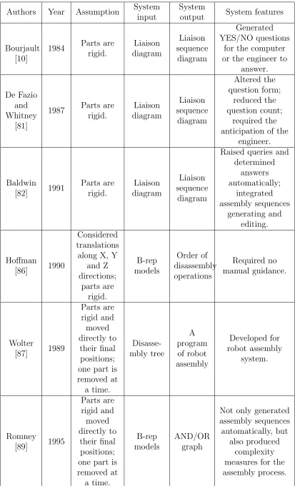
A summary of the above literature on the development of assembly planning systems is shown in Table 2.6.
Table 2.6: A summary of literature on the development of assembly planning
systems
Authors Year Assumption System input
System
output System features
Bourjault [10]
1984 Parts are rigid. Liaison diagram Liaison sequence diagram Generated YES/NO questions
for the computer or the engineer to
answer.
De Fazio and Whitney
[81]
1987 Parts are rigid. Liaison diagram Liaison sequence diagram Altered the question form; reduced the question count; required the anticipation of the
engineer. Baldwin [82] 1991 Parts are rigid. Liaison diagram Liaison sequence diagram
Raised queries and determined answers automatically; integrated assembly sequences generating and editing. Hoffman [86] 1990 Considered translations along X, Y
and Z directions; parts are rigid. B-rep models Order of disassembly operations Required no manual guidance. Wolter [87] 1989 Parts are rigid and moved directly to their final positions; one part is removed at a time. Disasse-mbly tree A program of robot assembly Developed for robot assembly system. Romney [89] 1995 Parts are rigid and moved directly to their final positions; one part is removed at a time. B-rep models AND/OR graph
Not only generated assembly sequences automatically, but
2.4.3
Assembly Sequence Planning Criteria
Once all feasible sequences are available, the second phase of assembly sequence planning entails the generation and application of criteria to reveal good sequence(s). The process of selecting an optimum sequence from the feasible sequences is called sequence editing as well.
Wolter proposed a list of criteria should be considered in evaluating an assembly plan, composed of directionality, fixture complexity, manipulability, locality and tool changes [86]. Homen de Mello and Sanderson introduced two criteria to select assembly plans: the first one is to maximise the number of different assembly sequences encompassed by the assembly plan; the second is to maximise the amount of parallelism or simultaneity that is possible in the execution of the assembly tasks [89]. Baldwin reported an integration of sequence generation and evolution containing two classes of sequence editing facilities [81]. One is editing states and moves which allowed deletion of assembly states which have multiple subassemblies, deletion of moves where a particular set of simultaneous mates is mode. This can quickly reduce the original large set of sequences to a reasonable few. And the other is editing all individual assembly sequences based on fixturing, refixturing, orientation, and reorientation issues.
Feasible assembly sequences can also be compared and selected based on time and cost. Kanai et al. developed a Computer Aided Assembly Sequence Planning and Evaluation system (ASPEN) which chooses an optimum sequence with the least operating time [90]. MTM (Methods Time Measurement) and DFA (Boothrouyd’s Design for Assembly) are used to evaluate the differences of operating time among feasible sequences explicitly. Lambert presented a dynamic programming algorithm for determining the optimum disassembly sequences of complex products with the objective of maximising the revenue [91]. Johnson and Wang introduced a procedure which integrates economical factors into the scheduling of disassembly operations aiming at improving the efficiency of the disassembly planning process and generating an optimum disassembly sequence with maximum profits [92]. Three criteria are established which are material compatibility, clustering for disposal and concurrent disassembly operations.
assembly sequence for a mechanical product [93]. Candidate sequences are selected one at a time by the SA algorithm and their costs are estimated by designing a minimum unit cost concept assembly system. Dini et al. described a method based on genetic algorithms for the generation and the evaluation of assembly sequences [94]. Optimum assembly sequences were obtained using an appropriate fitness function which takes into account simultaneously the geometrical constraints, the minimisation of tool changes and object orientation, and the possibility of grouping similar assembly operations. Tseng et al. applied the memetic algorithm which is an extension of the traditional genetic algorithm for sequences optimisation, whose optimisation function is determined by the similarity of the engineering data of the connectors since the arrangement of similar connector can reduce the changes of assembly tools and direction, thus reducing assembly time accordingly [95].
Manual Assembly Process
Simulation
3.1
Introduction
The importance of ergonomic considerations in the early phase of product and production system design is clearly evident, however, its implementation remains a great challenge [98]. In order to assist engineers when considering ergonomics, a number of commercial ergonomics simulation software tools have been incorporated with the basic ergonomics analysis functionalities for evaluating human factors in the design of product and process. DELMIA is one example, which allows a systematic analysis on products, processes, as well as operators in the development of products and production systems.
This chapter describes the implementation of ergonomics simulation and analysis for manual assembly in DELMIA. A brief introduction of DELMIA is presented in Section 3.2 first. Its functionalities in the ergonomics simulation and analysis are described separately in Sections 3.3, 3.4 and 3.5. Finally, the manual assembly process is simulated. General ergonomic issues identified in the process are analysed by means of two case studies: one is the manual assembly of a formula student car presented in Section 3.6, and the other is an aluminium blower assembly presented in Section 3.7.
3.2
Simulation Tool: DELMIA
DELMIA, stands for Digital Enterprise Lean Manufacturing Interactive Application, is a leading software tool for digital manufacturing solutions, which
![Figure 1.1: Market values of enterprises [2].](https://thumb-us.123doks.com/thumbv2/123dok_us/8069953.226794/17.596.224.413.533.636/figure-market-values-of-enterprises.webp)
![Figure 3.10: A 90% reach envelope [99].](https://thumb-us.123doks.com/thumbv2/123dok_us/8069953.226794/60.596.171.460.338.561/figure-a-reach-envelope.webp)
![Figure 3.12: A head clearance analysis [102].](https://thumb-us.123doks.com/thumbv2/123dok_us/8069953.226794/61.596.185.447.124.334/figure-a-head-clearance-analysis.webp)