link level library (3l) Interface
Spedfication
For 3Corn Network Adapter Products
Copyright © 3Com Corporation, 1987, 1988, 1989. All riglm,~.wt
3165 Kifer Road
Santa Clara, California 95052-8145 Printed in the U.S.A.
Copyright Statement
No part of this manual may be reproduced in any form or by any means or used to make
any
derivative (such as translation, transfonnation or adaption) without permission from 3C<ml Corporation, by the United States Copyright Act of 1976, as amended.Disclaimer
3Com makes no warranty of any kind with regard to this material, including, but not limited to, the implied warranties of merchantability and fitness for a particular purpose. 3Com shall not be liable for errors contained herein or for incidental or consequential damages in connection with the furnishing, performance, or use of this material.
Contents
Chapter 1: Introduction
Chapter 2: Architecture
Synchronous vs. Asynchronous Operation 2-2
Chapter 3: Interface Routine Specifications
Listing by Category 3-1 Initialization Routines 3-1 Control Routines· 3-1
Receive Packet Routines 3-2 Transmit Packet Routines 3-2 Routine Descriptions 3-3
InitAdapters - Initialize Network Adapters 3-3 InitParameters - Initialize Parameters 3-4 ResetAdapter - Reset Adapter 3-5
WhoAml - Who Am I Hardware Self Identification/Status Report 3-6 RdRxFilter - Read Receive Filter 3-8
WrRxFilter - Write Receive Filter 3-9
ExitRcvlnt - Protocol Time Critical Receive Processing 3-10 GetRxData - Get Received Data 3-11
RxProcess - Post the Received Packet for Protocol Side 3-12 SetLookAhead - Set Packet Header Length 3-14
PutTxData - Put Transmission Data 3-15 TxProcess - Transmit Complete Processor 3-17
Chapter 4: Error Handling
Error Handling Notes 4-1
Completion Code Assignment 4-2
Appendix A: Hardware Implementation Specifics
EtherLink (3C501) A-1 Package Contents A-1 Transmission Capabilities A-1 Initialization Parameters A-1 WhoAml Statistics A-2 Other A-2
EtherLink II (3CS03) A-2 Package Contents A-2 Transmission Capabilities A-2 Initialization Parameters A-3 WhoAml Statistics A-3 EtherLinklMC (3CS23) A-4 Package Contents A-4 Transmission Capabilities A-4 Initialization Parameters A-4 WhoAml Statistics A-4 Other A-4
Tokenlink (3C603) A-S Package Contents A-5 Transmission Capabilities A-5 Initialization Parameters A-5 WhoAml Statistics A-5 Other A-5
3Station (3C1100) A-6 Package Contents A-6 Transmission Capabilities A-6 Initialization Parameters A-6 WhoAml Statistics A-6 Other A-6
Appendix B: Implementation Syntax
a,nd
Naming
Appendix C: Example
Figures
2-1. Transmit Processing 2-3 2-2. Receive Processing 2-4
Link Level Library:
1
Introduction1-1
Chapter 1:
Introduction
This document describes the 3eom Link Level Library (3L) Interface. It is intended to assist engineers developing or modifying network software to run on 3eom network adapters that have a 3L implementation available.
3L consists of a set of generic routines that provide the protocols with a flexible means of
transmitting and receiving packets over the network, while at the same time isolating the protocols from the specific network adapter hardware in use. Each 3L implementation for 3Com' s various adapters interface to any protocols that network 3L to "talk" to the network. 3L implementations allow both Ethernet and token ring physical layers to support the same network operating system.
Chapter 2 describes the concepts and facilities of 3L, and outlines the architecture by identifying general usage of interface routines.
Chapter 3 specifies each routine that is to reside on either side of the 3L interface. For each routine, the input parameters, output parameters, and function are defined, and special notes regarding usage are included, as appropriate.
Chapter 4 describes the error handling conventions to be used by all routines defined in the specification.
Appendix A describes the specific issues for the several 3eom 3L implementations. The appendix has a single section for each 3eom network adapter for which the interface has been implemented.
Appendix B discusses the specifics of linking the routines using the Microsoft OBJ format conventions.
Link Level Library:
2
Architecture2-1
Chapter 2: Architecture
The following specification is technical in nature, and is intended for experienced 8086 programmers with specific understanding of the architecture of 808x-based and 80x86-based microcomputers, and of programming interrupt driven device drivers. An assembler should be used that generates object modules that are MicrosoftlIntel compatible.
The 3L routines are intended to allow protocols to communicate with one or more network adapters. The routines are designed to be directly linked to protocol software. These routines provide four areas of service for the protocols running "above" the 3L-based driver. These are:
• Network adapter initialization
• Delivery of received packets to higher level protocols
• Transmission of packets onto the network
• Control functions
The 3L interface is specified in a manner so as to support the range of network hardware interface architectures in use and under development today. In particular this architecture allows for the synchronous/asynchronous operation of the transmission process. Each implementation of 3L supports one or both of these approaches. Protocol software interfacing to 3L routines may select either one, if both approaches are implemented. Protocol software may determine which
transmission approach is available through the WhoAmI function call at initialization time. Availability and selections will be based on the following:
• Network controller hardware design
• Specific 3L implementation design
• Performance requirements
2
Link Level Library: Architecture2-2
Synchronous vs. Asynchronous Operation
To provide the most flexibility and perfonnance, the 3L interface presented to the protocols appears to be asynchronous. "Appears to be" is appropriate because a specific 3L implementati<tft mayor may not implement an asynchronous interface. Asynchronous drivers will either start the requested operation, or queue up the operation for starting later, as appropriate for the current state of the driver. In either case, an asynchronous driver will return immediately to the routine requesting the operation. At a later time, the asynchronous driver interrupts and informs the requesting routine that the operation previously requested has been completed. This method allows the 3L routines and the protocols to continue simultaneously, improving overall performance. To ease implementation, a synchronous hardware driver may be used in place of a true asynchronous hardware driver. Synchronous 3L routines start the requested operation, wait for it to complete, and infonn the requesting routine that the operation has completed before returning to the protocols. The net result is that the synchronous driver appears to be a very fast asynchronous driver to the routine requesting the service, since the requested operation is completed before the called routine returns. Truly asynchronous operation of receive and transmit functions mayor may not be able to be provided in a given 3L implementation for a specific network hardware interface. Also, protocols linking to and using the 3L implementation mayor may not choose to implement the logic required to use this asynchronous operation capability. Two design features are provided for protocol developers wanting to use this capability. These are the Request Identifier and the NO-WAIT mode post routine use.
Since the interface may support asynchronous operations, a Request Identifier (I-byte long) is
provided by the 3L routines to keep track of which request is being referred to in a given routine call. A unique request identifier is generated by the 3L routines at the beginning of each transmit or
receive function sequence. The protocols must keep this identifier and pass it to the 3L routines on · any subsequent routine call during the processing of that particular transmit or receive packeL
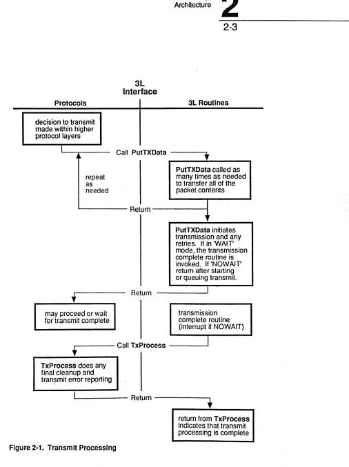
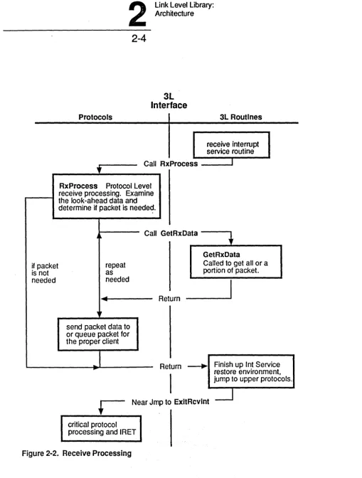
Most of the routines defined in this document comprise the 3L. There are two additional routines defined, RxProcess and TxProcess, which may be provided by the protocols. Of these,RxProcess is required and TxProcess provides a capability of executing transmit operations in a no-wait mode. This two-way interface greatly simplifies the interaction of the 3L routines and the protocol routines.
Protocols
decision to transmit made within higher protocol layers
repeat as needed
link Level library:
2
Architecture3L
Interface
Call PutTX Data
2-3
3L Routines
"
PutTXData called as many times as needed to transfer all of the packet contents
L . . -_ _ _ _ _ Return
may proceed or wait for transmit complete
Return
~Ir
PutTXData initiates transmission and any retries. If in 'WAIT' mode I the transmission
complete routine is invoked. If 'NOWAIT' return after starting or queuing transmit.
transmission complete routine (interrupt if NOWAIT)
,r---
Call TxProcess _ _ _---.JI
TxProcess does anyfinal cleanup and transmit error reporting
[image:8.612.71.577.59.736.2]L . . -_ _ _ _ _ Return - - - ,
Figure 2-1. Transmit Processing
if packet is not needed
2
Link Level Library: Architecture2-4
3L Interface
Protocols 3L Routines
receive interrupt service routine Call RxProcess I
RxProcess Protocol Level receive processing. Examine the look-ahead data and determine if packet is needed.
Call GetRxData - - - - .
repeat as needed
send packet data to or queue packet for the proper client
...
Return
GetRxData
Called to get all or a portion of packet.
Return ~ Finish up Int Service restore environment, jump to upper protocols.
Near Jmp to ExltRcvlnt
[image:9.626.42.552.46.719.2]critical protocol processing and IRET
Link Level Library:
3
Interface Routine Specifications3-1
Chapter 3: Interface Routine
Specifications
This chapter contains two sections. The first section consists of a list of the interface routines by category. The second section contains detailed descriptions of the routines.
Listing by Category
Initialization Routines
Routine Name Locus
. InitAdapters 3L
InitParameters 3L
ResetAda pter 3L
WhoAmI 3L
Control Routines
Routine Name Locus
RdRxFiIter 3L
WrRxFilter 3L
Descri ption
Initializes the adapter hardware into a fully configured, but not yet enabled, state.
Sets up data structures for the 3L code with configuration infonnation connecting the adapter with the host computer.
Resets an adapter to its configured, but not yet enabled, state.
Returns identification and current status infonnation about the adapter and the 3L software to the upper protocols.
Descri ption .
Infonns upper protocols of the types of packets.
3
Link Level Library:Interface Routine Specifications
3-2
Receive Packet Routines
Routine Name Locus Description
ExitRcvlnt protocol Accomplishes final protocol side time-critical processing and performs the IRET that exits the interrupt context
NOTE: ExitRcvlnt is defined as a near label, rather than as a PROe.
GetRxData 3L Allows data from the received packet to be read by the
protocols. Also allows buffers to be released for use in storing packets upon reception.
RxProcess protocol Posts the receipt of the packet or accomplishes the receive processing at the protocol level itself.
SetLookAhead 3L Specifies an initial portion of all packet headers that are to be presented to the protocol side when the call to RxProcess is made from the 3L receive handler.
Transmit Packet Routines
Routine Name Locus Description
PutTxData 3L Transfers data to be transmitted from the protocol.
Link Level Library:
3
Interface Routine Specifications .3-3
Routine Descriptions
Note Regarding General Use of Registers
In the following routine descriptions, registers DI, SI, BP, and DS are presumed to be preserved by each function, unless otherwise noted. Contents of other registers are not guaranteed, except as specifically noted. Many routines require DL=O. This was intended as the adapter number but only one adapter (adapter 0) is supported in this version. Each routine specified here is to be coded as a near procedure (PROC NEAR routine name).
InitAdapters - Initialize Network Adapters
Procedure type: Near.
Locus: Hardware.
Call with: DI = Offset address of the RxProcess routine within CS.
Return with: AX = Completion code.
CX
=
Number of adapters of this type found.This function initializes the adapter hardware, runs any diagnostics on the adapter hardware, initializes any interrupt vector(s) to be used by the adapter(s), sets up any DMA channel(s) to be used by the adapter(s), reads the network address of the board, writes the network address to the controller (as appropriate), initializes the transmit data counter to zero, and initializes the receive packet filter to no packets.
3
Link Level Library:Interface Routine Specifications
3-4
InitParameters - Initialize Parameters
Procedure type:
Locus:
Call with:
Return with:
Near.
Hardware.
ES:BX= Address of the DOS device driver INIT call request header.
AX
=
Completion code. ES:BX=
Unchanged.This is the lowest level init function and should be called first during initialization. This function sets up internal data structures that are needed to interact with the adapter. This involves defining values specific to this board and this host computer environment, and may include intetrupt
channel(s) to use, DMA channel(s), DMA modes for input and for output, type of host, 110 memory addresses, etc. Also, various special hardware mode condition variables may be set.
Link Level Library:
3
Interface Routine Specifications3-5
ResetAdapter - Reset Adapter
Procedure type: Near.
Locus: Hardware.
Call with: DL=O
Return with: AX
=
Completion code.3
Link Level Library:Interface Routine Specifications
3-6
WhoAml - Who Am I Hardware Self
Identification/Statu.s~eportProcedure type: Near.
Locus: Hardware.
Call with: DL=Q
Return with: AX
=
Completion code.ES:DI
=
Pointer to N byte structure holding the interesting infonnation.Offset
[ptr
+
0][ptr + 6] [ptr + 7] [ptr
+
8][ptr + 9] [ptr
+
10][ptr+ 11] [ptr
+
12] [ptr+
13] [ptr + 14][ptr + 16]
Descri ption • Size
Adapter Network Address/ Extended Structure Indicator. Software major version number. Software minor version number. Software sub version.
Software type d or s (development or ship). Adapter type.
Bits 0-5: adapter type ID (0 - 63)
1
=
EtherLink (IEl)2
=
EtherLink (IEI, IE2, or IE4) 3=
EtherLink Plus4
=
EtherLink/MC 5=
TokenLink Plus 6=
EtherLink II7
=
TokenLink 8=
Reserved9 = Reserved
10
=
IBM Token Ring 11=
3Station, 3Station/2E12 -63
=
reservedBit 6: hardware interface code location
o
= host processor based1 = adapter processor based
Bit 7: network type - not used in extended structure form
o
=
Ethernet 1=
Token Ring Initial status of hardware. ReservedNumber of transmit buffers. Size of transmit buffers.
Number of transmissions since reset.
6 bytes I byte BCD 1 byte BCD
1 byte ASCII char 1 byte ASCII char
1 byte
Offset
[ptr
+
20] [ptr+
24] [ptr+
28] [ptr+
32] [ptr+
36] [ptr+
40] [ptr+
44][ptr
+
45][ptr
+
46]Link Level Library:
3
Interface Routine Specifications3-7
Description
N umber of transmit errors since reset. Number of transmit timeouts since reset. Number of receptions since reset.
N umber of broadcasts received since reset. Number of receive errors since reset. Number of retries since reset.
Data transfer mode control.
Bit 0
=
0 gather pieces must start on bytes.Bit 0
=
1 gather pieces must start on word address. Bit 1=
0 gather piece length is any number of bytes. Bit 1=
1 gather piece length is even number of bytes. WAIT/ NOWAIT transmission capability.o
=
only WAIT option is available in calls to PutTxData. 1=
both WAIT and NOWAIT options are available. Start of hardware specific data.Size
2 words 2 words 2 words 2 words 2 words 2 words 1 byte
This function returns infonnation about the current state of the hardware and software for a specific adapter.
The routine returns an address of a data structure that may be shared by the hardware and the protocols. Several statistics may be maintained from within the hardware portion and the protocol side may at any time read and/or reset these data items. For perfonnance reasons, these statistics may be maintained only by versions of hardware side implementations that have been created for this purpose. (The fastest driver may not take time to count up things such as received packets.)
Note that two types of structures are defined. The standard structure contains 46 bytes of
infonnation and may be followed by hardware specific data. This structure is used for Ethernet and token ring networks. The extended structure allows for other network types. It is indicated by the Adapter Network Address field ([ptr + 0], 6 bytes in length) having all bits set: address
=
255-255-255-255-255-255. In this case, location [ptr + 46] contains the 2-byte offset of an extension to this structure, allowing for network addresses of lengths other than 6, and network types other thanEtherne~ and token ring.
3
Link Level Library:Interface Routine Specifications
3-8
RdRxFilter - Read Receive Filter
Procedure type:
Locus:
Call with:
Return with:
See related routines:
Near.
Hardware.
DL=O
AX = Completion code.
BX
=
Filter setting. WrRxFilter.This function retrieves the current filter setting from the LAN hardware controller for the specified adapter.
Note Regarding Packet Filter Settings:
The receive filter setting referred to in this routine is used to set the receive mode of the network adapter. There are four basic parts to the filter setting, each one represented by one bit in the filter setting word. Combinations of settings 1, 2, and 4, may be used as appropriate.
Receive no packets (receiver disabled). Receive packets for the adapter address. Receive multicast or group packets. Receive broadcast packets.
Receive all packets.
*
OOOOh OOOlh 0002h 0004h 0008h
*
Promiscuous mode: all physically addressed packets are received.Link Level Library:
3
Interface Routine SpecificationsWrRxFilter - Write Receive Filter
Procedure type:
Locus:
Call with:
Return with:
See related routines:
Near.
Hardware.
AX = Filter setting.
DL=O
AX = Completion code.
RdRxFilter.
3-9
This function sets a new filter setting and enables or disables the adapter. It is the responsibility of the protocol software to keep track of the old filter (if it is needed later) by using RdRxFilter. If the filter setting is zero, no packets are to be received, and this function call will disable packet reception on the adapter. If the filter setting is a valid non-zero value, the receiver will be enabled, and the filter setting will be provided to hardware to accomplish the filtering, or will filter in software, per specific hardware capabilities.
Note Regarding Packet Filter Settings:
The receive filter setting referred to in this routine is used to set the receive mode of the network adapter. There are four basic parts to the filter setting, each one represented by one bit in the filter setting word. Combinations of the first three settings may be used as appropriate. (See Rd Rx Filter.)
Receive no packets (receiver disabled). Receive packets for the adapter address. Receive multicast or group packets. Receive broadcast packets.
Receive all packets.
*
OOOOh
OOOlh
0002h
0004h
0008h
*
Promiscuous mode: all physically addressed packets are received.Specific handling of these settings may vary somewhat from implementation to implementation, i.e., not all settings may be available on any particular network adapter controller. Token ring
3
Link Level Library:Interface Routine Specifications
3-10
ExitRcvlnt - Protocol Time Critical Receive Processing
Label type:
Locus:
Jump to with:
Return:
Near.
Protocol.
Machine context exactly as established at the time the receive intm-upt from the adapter occurred. (In other words, all registers, excepting CS, IP, and Flags, contain the values of the interrupted process. CS, IP, and
rae
Flags register contents are on the interrupted process stack as in standard 80x86 interrupt context.)Return is made to the interrupted process directly via an IRET. Daes not return to the 3L routine that jumped to this label.
This label is reached via ajump made by the interrupt service routine (which exists in the 3L code). The hardware side has restored the context in which the interrupt was received, and is ready for return to it. The jump to the protocol side is made to allow the protocols to accomplish any additional time-critical processing prior to returning to the interrupted process.
Example Usage:
In the 3Com XNS environment, ExitRcvInt performs certain critical functions that would otherwise be done the next time the XNS process manager got control. In this case, the process manager gets control via the next timer tick, and this interface allows the initiation of its tasks immediately upon completion of the link layer receive functions, avoiding a potential average latency of 5et percent of the timer tick period.
Link Level Library:
3
Interface Routine Specifications3-11
GetRxData - Get Received Data
Procedure type:
Locus:
Call with:
Near.
Hardware.
CX
=
Count of bytes to transfer or size of buffer to release. DL=
Adapter number and flags.Bit 0, 1 = 0
Bit 6 (Buffer Release)
=
1 if buffer may be released.= 0 to retain the packet in the hardware buffer.
Bit 7
=
0 DH=
Request identifierES :DI
=
Address of buffer to place packet data.Return with:
AX = Completion code.
ex
=
Actual count of bytes transferred. ES:DI=
Preserved.See related routine: RxProcess.
This function obtains the requested amount of data from the packet indicated by the request
identifier and also serves the function of releasing buffers for use by the hardware in storing packets received from the network medium. The Request Identifier is supplied when Rx Process is called.
ES:DI contains an address to which data is to be copied, with the amount to be copied specified in CX. The first call to GetRxData for a packet will obtain data from the start of the packet.
Subsequent calls to GetRxData will return data that immediately follows the portion of the packet that was previously obtained. The buffer release bit operates independent of any request to copy data, and CX may be 0, indicating release only.
Buffer Release
3
link Level library:Interface Routine Specifications
3-12
RxProcess - Post the Received Packet for Protocol Side
Procedure type:
Locus:
Call with:
Near.
Protocol.
AX AH AH AL
ex
DL
DH ES:DI
=
=
=
=
=
=
=
Receive status.
o
success. 1 failureReserved for future use expanding receive status.
Size of received packet.
o
Request identifier.
Address of virtual packet header (see below).
Return with: DS, SI, DI destroyed.
See related routines: SetLookAhead GetRxData.
This is a protocol-level receive packet processing routine. The routine is called by a hardware side receive routine, which is either an interrupt handler responding to a packet received interrupt or a subroutine of a polling control module which has noted a received packet. The basic receive packet processing sequence is outlined in the introduction section to this document. The main task for RxProcess is to obtain information about what to do with the packet, and what additional processing by protocol software is required to either complete that processing, or to enqueue the task for
protocol software to complete it when it is no longer in the system interrupt context. The Request Identifier that is provided is used in subsequent calls to GetRxData.
Note Regarding Time Within Interrupt Context:
It is anticipated that overall system performance will be best enhanced by remaining in the interrupt context for a minimum period of time and, as such, protocols will generally attempt minimum functions in this routine to get the packet and set it up for later processing. When the processing of the received packet is finished, RxProcess simply returns to the receive interrupt service routine that called it.
Note Regarding Buffer Usage:
Link Level Library:
3
Interface Routine Specifications3-13
Note Regarding Virtual Header:
ES:DI points to a copy of packet header data. This structure provides protocol software a "look ahead" at bytes from among the first 64 bytes of the received packet. It is provided to allow RXProcess greater intelligence in the selection of a buffer into which GetRxData will copy the packet data. The contents of the virtual header are defined by one or more calls to SetLookAhead prior to the receipt of the packet in question. Each such call specifies the number of bytes from among the first 64 in each packet header which RxProcess will have available for use in its initial processing. The virtual header itself contains a copy of the beginning of the packet, of a length equal to the largest number ever requested in a call to SetLookAhead, up to a maximum of 64 bytes.
Example Usage:
3
Link Level Library:Interface Routine Specifications
3-14
SetLookAhead - Set Packet Header Length
Procedure type: Near.
Locus: Hardware.
Call with: CX
=
Number of bytes in list.DL=O
Return with: AX
=
Completion code.See related routine: RxProcess.
This function allows protocol software to specify the number of bytes within received packet headers that will be provided by the hardware side receive routine (either interrupt handler or subroutine of polling control module) for inspection by the protocol side RxProcess routine. This is information which the protocol routine RxProcess may use to "look ahead" into the packet to determine where to route the packet among its own clients. Use of this mechanism (to specify "look ahead" data that is provided to RxProcess in the form of the "virtual header") is to allow a performance gain in
RxProcess. RxProcess is able to use look ahead data to determine which client the packet is intended for, and can make its calls to GetRxData using addresses of protocol buffers most
appropriate for the particular packet. An example is the MINDSIXNS protocol using the packet type and IDP socket number to determine which client's buffer to have the packet transferred into,
Link Level Library:
3
Interface Routine Specifications3-15
PutTxData - Put Transmission Data
Procedure type: Near.
Locus: Hardware.
Call with: BX
=
Total length of packet (first call only). CX=
Count of bytes to transfer.DL
=
Flags: Bit 0-1=
0Bit 4 NOW AIT transmit:
= 1 to start transmission after this data transfer and return to caller as soon as transmit is initiated.
= 0 to just transfer data. Bit 5 WAIT transmit
=
1 to start transmit after this data transfer and await transmit completion before returning.= 0 to just transfer data. Bit 6 First data transfer call
= 1 if first data transfer call for this packet.
= 0 if subsequent data transfer call for this packet. Bit 7
=
0DH = Request identifier (unused if first data transfer). DS:SI
=
Address of data to transmit.DI
=
Address of TxProcess post routine (fust call only).Return with: AX
=
Completion code.DH
=
Request identifier (if first call).See related routine: TxProcess.
This function transfers a block of data that is to be transmitted. This function uses the transmit packet data counter to determine how far into the transmit packet to place the new data and adjusts the transmit packet data counter appropriately to account for the data just transferred. This ensures that subsequent calls to PutTxData will continue building the packet to transmit where the previous call left off. The transmit packet data counter is reset only when a packet transmit is started.
TxProcess Address
3
Link Level Library:Interface Routine Specifications
3-16
W AITINOW AIT
link Level library:
3
Interface Routine Specifications3-17
TxProcess - Transmit Complete Processor
Procedure type:
Locus:
Call with:
Near.
Protocol.
AX
=
Transmit status: AH = 0 success. AH=
1 failure. AL=
Reserved.DL=O
DH = Request identifier.
Return with: AX, BX,
ex,
DX, ES destroyed. BP, SI, DI, DS preserved.See related routine: PutTxData.
This function is a completion processing routine existing on the protocol side of the interface. It is called when hardware has completed a transmission initiated by a call to PutTxData. The address of this routine was passed by the protocol side when the call to PutTxData was made. Thus, several distinct TxProcess routines may exist in the protocol software for different control requests or for other distinct purposes. The hardware side may queue transmission requests, distinguishing them via request identifiers.
Link Level Library:
4
Error Handling4-1
Chapter
4:
Error Handling
Error Handling Notes
A. All of the hardware dependent routines defined here return a completion or error code in register AX upon exiting. The value of this return code signifies that either the routine completed its appointed duties successfully, or that a problem of some sort was encountered.
The method used here to assign completion codes provides a simple means of checking for and processing errors on three different levels of detail:
• The code may be checked simply for successful or unsuccessful completion of the request.
• The code may be checked to detennine the general type of error encountered, such as a bad parameter or transmission failure.
• The code may be checked to detennine the specific error encountered, such as an expired retry counter.
B. The method used to provide this flexibility in error handling is simple. The total range of completion codes is first split into several subranges. Each subrange is then associated with a specific category of error. Finally, individual codes within each subrange or category of codes are assigned to specific error conditions, as required.
c.
By using this method, and by choosing an error subrange size of 256, the three types of error checking discussed above may be implemented by the following methods:• The simple success/failure test is done by testing AX for a zero or nonzero value.
• The general error category test is done by testing the value in AH. Since an error subrange size of 256 was chosen, each subrange will provide a unique value in AH. For example, an incorrect parameter passed to a routine would return a completion code in the lOOh-IFFh range, giving a value ofOIh in register AH.
4
Link Level Library: Error Handling4-2
• Since the completion code is returned in a 16-bit register, the total number of completion codes is rather large (65000+), allowing a generous initial allocation of completion code subranges. The allocation of completion codes and categories is defined in the
"Completion Code Assignment" section of this document.
D. For consistency and convenience, the first completion code in each range is defined as a general failure of the given category. In this way, a routine need not allocate specific completion codes for generic errors.
Completion Code Assignment
•
The allocation of completion code ranges to error categories follows:
Code range Error category
0 No error
OlOOh-OIFFh Parameter errors
0200h-02FFh Miscellaneous host errors 0300h-03FFh Adapter initialization errors 0400h-04FFh Adapter transmission errors OSOOh-OSFFh Adapter receive errors 0600h-06FFh Miscellaneous adapter errors 0700h-07FFh Reserved
0800h-08FFh Reserved
Specific completion code definitions follow:
No error encountered
No error. Request completed successfully.
Parameter errors
OIOOh OIOlh Ol02h
General parameter error Reserved
Invalid data transfer method
Miscellaneous host errors
Link Level Library:
4
Error HandlingAdapter initialization errors
0300h
0301h
0302h
0303h
0304h
0305h
0306h
0307h
0308h
General adapter initialization error Problem while locating adapters Unable to initialize adapter Adapter diagnostic failure
Unable to read network address from adapter Unable to write network address to adapter Invalid network address
Invalid receive filter setting
Unable to read receive fliter setting
Adapter transmission errors
0400h
0401h
0402h
0403h
0404h
0405h
General adapter transmission error All transmit buffers in use, try again later Maximum packet length exceeded
Unable to load packet data to adapter Unable to start transmission
Transmission retry count exceeded
Adapter receive errors
0500h
0502h
0503h
0504h
0505h
0506h
0507h
0508h
General adapter receive error Receive interrupts already enabled Unable to disable receive interrupts Receive interrupts already disabled End of packet data reached
Unable to read packet information Unable to read packet data
Unable to reann adapter for reception
Miscellaneous adapter errors
0600h
0601h
0603h
0604h
0605h
0606h
General adapter error Shared buffers not available Command rejected
Command timed out with no response Unable to initiate data transfer
Unable to complete data transfer
Link Level Library:
A
Hardware ImplementationSpecifics
A-1
Appendix A: Hardware Implementation
Specifics
EtherLink (3C501)
Package Contents
The package for this adapter consists of the source code and a "lib'd" version of the 3L library. The source files are:
501 CfRL.ASM 501DATA.ASM 501INIT.ASM 501INTR.ASM 501RECV.ASM 501UTIL.ASM 501XMIT.ASM 501VER.ASM
- RdRxFilter and WrRxFilter - Data declarations
- ResetAdapter, WhoAmI, InitAdapters and InitParameters - Interrupt service routine
- GetRxData
- Various hardware utility routines PutTxData
- Version string data declaration
Transmission Capabilities
Only WAIT mode transmits are supported.
Initialization Parameters
InitParameters interprets the DOS device driver INIT request header pointed to by ES:BX. At offset 18 from the start of this structure is a pointer to an ASCII string which is the parameter list after the 'device=' statement in the CONFIG.SYS file. The parameter list must have the following format:
where:
<filename> <i>
<bbb> <d> <t>
A
A-2
Link Level Library:
Hardware Implementation Specifics
is the name of the device driver file is the interrupt level
is the
I/O
base address (in hex) is the DMA channelis the DMA transfer mode: t
=
1 DMA single byte mode t=
2 Programmed I/O loopt
=
3 DMA block or demand mode as supported by the adapter t = 4 ProgrammedI/O
"rep"All of the parameters are position dependent.
WhoAml Statistics
No statistics in the WhoAmI data structure are maintained.
Other
The only valid RxFilter settings are:
o
Receive no packets5 Receive station address and broadcast packets
7 Receive station address, multicast and broadcast packets 8 Receive all packets (promiscious mode)
EtherLink II (3C503)
Package Contents
The package for this adapter consists'of the source code and a "lib'd" version of the 3L library. The source files are:
EHWINIT.ASM EHWRECV.ASM EHWXFER.ASM EHWRTN.ASM EHWDATA.ASM EHWXMIT.ASM TIMER.ASM
- InitParameters
- GetRxData and the interrupt service routine - SetLookAhead
- ResetAdapter, RdRxFilter,WrRxFilter, WhoAmI, and InitAdapters - Data declarations
- PutTxData
- Optional timer routines
Transmission Capabilities
Link Level Library:
A
Hardware ImplementationSpecifics
A-3
Initialization Parameters
InitParameters interprets the DOS device driver INIT request header pointed to by ES:BX. At offset 18 from the start of this structure is a pointer to an ASCn string which contains the driver name, optionally followed by one or more of the following parameters:
Use interrupt level 'x'
lI:x
/A:xxx Use 'xxx' for the I/O base address of the adapter, where 'xxx' is a three-digit hex number.
/D:x {f:x
/M:x
Use DMA channel 'x' Use transceiver 'x':
x
=
1 BNC/Onboard x = 2 DIX/Extemal Use data transfer mode 'x':x = 1 DMA single byte mode x = 2 Programmed I/O loop
x
=
3 DMA block or demand mode as supported by the adapter x = 4 Programmed I/O "rep" (default for 286-based machines)WhoAml Statistics
Four of the statistics counters in the WhoAmI data structure are implemented. The other statistics counters have not been implen1ented for performance reasons and will remain at zero. The counters which are kept are:
[ptr+ 16] Number of transmissions [ptr+24] Number of transmit timeouts [ptr+28] Number of receptions
[ptr+ 36] N umber of receive errors
These statistics are not cleared during a reset. The hardware specific portion of the WhoAmI structure is defined as follows:
[ptr+46] N umber of jams
[ptr+50] Number of receive overflows
[ptr+54] Number of short packet~ (runts) received
2 words 2 words 2 words
A
A-4
Link Level Library:
Hardware Implementation Specifics
EtherLinklMC (3C523)
Package Contents
The package for this adapter consists of the source code and a "lib' d" version of the 3L library. The source files are:
523CfRL.ASM 523UTIL.ASM 523DATA.ASM 523INIT.ASM 523INTR.ASM 523RECV.ASM 523XMIT.ASM
- RdRxFilter and WrRxFilter
- Various hardware dependent routines - Data declarations
- ResetAdapter, WhoAmI, InitAdapters and InitParameters - Interrupt service routine
- GetRxData and SetLookAhead - PutTxData
Transmission Capabilities
Only WAIT mode transmits are supported.
Initialization Parameters
There are no initialization parameters.
WhoAml Statistics
Statistics are kept in the WhoAmI data structure if the DEV compiler flag is turned on.
Other
The only valid RxFiIter settings are:
o
Receive no packets1 Receive station address packets
3 Receive station address and multicast packets 5 Receive station address and broadcast packets
Link Level Library:
A
Hardware ImplementationSpecifics
TokenLink (3C603)
Package Contents
A-5
The package for this adapter consists of the source code and a "lib' d" version of the 3L library. The source files are:
TOKENS.ASM TIMER.ASM
- All 3L source code
- Optional timer interface routines
Transmission Capabilities
Both WAIT and NOWAIT transmissions are supported. If more than eight NOWAIT transmits are queued up, awaiting transmission, PutTxData will return an error indicating that no more buffers are available.
Initialization Parameters
InitParameters interprets the DOS device driver INIT request header pointed to by ES:BX. At offset 18 from the start of this structure is a pointer to an ASCII string which may be composed of the following position dependent parameters:
<filename>.sys <i> <bbb> <d> <w>
where:
<filename> .sys <i>
<bbb> <d> <w>
is the name of the device driver. This must end with the letters uSYS".
is the interrupt level '
is the I/O base address is the DMA channel
is the number of wait states
WhoAml Statistics
The WhoAmI data structure is only partially implemented. The network address, transmit counts and receive counts are the only fields that are maintained in the entire structure.
Other
The only valid RxFilter settings are:
o
No packet are receivedA
A-6
Link Level Library:
Hardware Implementation Specifics
3Station (3C11 00)
Package Contents
The package for this adapter consists of the source code and a "lib'd" version of the 3L library. The source files are:
110OCTRL.ASM ll00DATA.ASM ll00INIT.ASM ll00INTR.ASM ll00RECV.ASM ll00UTIL.ASM ll00VER.ASM ll00XMIT.ASM
- RdRxFilter, WrRxFilter and SetControl - Data and structure declarations
- InitAdapter, ResetAdapter, WhoAmI and InitParameters - Receive interrupt service routine
- GetRxData and SetLookAhead - Utility routine used by other modules - Version number string
- PutTxData
Transmission Capabilities
Only WAIT mode transmits are supported. If NOW AIT request are made to PutTxData, they will be handled as WAIT mode transmits. Due to the nature of the hardware, when the receiver is enabled/disabled the transmission is also enabled/disabled.
Initialization Parameters
InitParameters receives in ES:BX the address of the DOS device driver INIT call request header, but does not use any run-time parameters. The routine does verify that the code is running on a 3Station. It also checks the hardware version number of the machine. The hardware version number is used to differentiate between the 3Station version released in April 1987 and future vensions. There are hardware bugs in the 3Station version released in April which should not be present in future versions of the 3Station. The variable "lite_flag" is set to 1 to allow the "xfer" routine (see 1100util.asm) to take advantage of the improved performance possible due to the hardware fixes.
WhoAml Statistics
No statistics are maintained in the WhoAmI data structure.
Other
Link Level Library:
B
Implementation Syntaxand Naming
8-1
Appendix B: Implementation Syntax
and
Naming
3Com currently implements both hardware and protocol side routines in 8086/80286 assembler source compatible with the Microsoft macro assembler, version 4.0. Hardware and protocol routines are maintained in separate modules, and linked with Microsoft's LINK, version 3.05.
Define each hardware side procedure as a public near procedure in source files where procedure code is included, and declare each as external near procedures in your source files where calls are made.
Implementation as a configurable DOS device driver allows specification of an end address for the code to DOS at the time configuration initialization completes. In the current MINDS
implementations, this driver is run at configuration initialization time, and then cut off by specifying a code end address to DOS which is just prior to this "use one time and throwaway" type code. In this MINDS implementation, the module ethdr.obj must be linked first (as it contains the DOS device driver header). Three SEGMENTS are defined to the linker, and are all grouped together so that all data and entry points are relative to the same start location for the driver.
The statements to declare statement in a module are:
;align all 3 segments
CODE GROUP RCODE, DATA, ICODE ;specify default label
;and variable registers
ASSUME cs:CODE,ds:CODE,ss:NOTHING, es:NOTHING
RCODE SEGMENT WORD PUBLIC ;DOS device driver header structure
;all executable code which is to be retained after configuration initialization time RCODEENDS
DATA SEGMENT WORD PUBLIC
;define data items which are to be retained DATA ENDS
ICODE SEGMENT WORD PUBLIC
near label CUTOFFPOINT: ;address to pass DOS for throwaway after init
;all executable code which is top be discarded after configuration initialization time ;all data items which are to be inserted
Link Level Library:
C
Interfacing to a 3L CompliantDriver Example
C-1
Appendix C: Interfacing to a 3L Compliant
Driver Example
This chapter contains listings providing example use of the 3L Interface. These listings are for illustration only and are not intended for direct inclusion in a developer's program.
c
C-2
Link Level Library:
Interfacing to a 3L Compliant Driver Example
title cto3l. asm
.******************************************************************
,
,
;File: CT03L.ASM
;
;Description: This file contains subroutines which provide a
; C program with an interface to the 3L 1.0 routines.
; .****************************************************************** , PUBLIC PUBLIC PUBLIC PUBLIC PUBLIC PUBLIC PUBLIC PUBLIC PUBLIC PUBLIC PUBLIC extrn extrn extrn PUBLIC PUBLIC PUBLIC extrn extrn extrn extrn extrn extrn extrn extrn extrn CODE TEXT DGROUP TEXT DATA DATA ICODE ICODE _getds cInitParameters =cInitAdapters _cResetAdapter cWhoAmI cRdRxFilter cWrRxFilter -cPutTxData -cGetRxData cSetLookAhead -etext
_myExitRcvInt :near
_myRxProcess :near
_myTxProcess :near
ExitRcvInt RxProcess TxProcess
InitParameters :near
Ini tAdapters - :near
ResetAdapter :near
WhoAmI :near
RdRxFilter :near
WrRxFilter :near
putTxData :near
GetRxData :near
SetLookAhead :near
GROUP _TEXT, DATA, ICODE
segment byte public 'CODE'
group DATA, BSS
assume cs:_TEXT, ds:DGROUP, ss:DGROUP ends
segment word public 'CODE' ends
Link Level Library:
C
Interfacing to a 3L CompliantDriver Example
C-3
DATA segment
his ds dw ?
etext db ?
DATA ends
DATA segment word public 'DATA'
-d@ label byte
-DATA ends
-BSS segment word public 'BSS'
-b@ label byte
-BSS ends
-DATA segment word public 'DATA'
s@ label byte
-DATA ends
TEXT SEGMENT
ASSUME CS: _TEXT, DS:DGROUP, SS:DGROUP
_getds proc near
mov aX,ds
mov cS:his _ds, ax
ret
_getds endp
i---i
i _cInitAdapters: This procedure provides the glue between a C
program and the 3L 1.0 InitAdapters function.
Calling Sequence:
int clnitAdapters( &nAdapters
Input Parameters: None
Output Parameters:
int nAdapters
Returns:
; The return value of the InitAdapters function
;---~---cInitAdapters
- push
mov push push push
proc bp bp,sp si di ds
mov ax,cs
mov ds,ax
c
C-4
Link Level Library:
Interfacing to a 3L Compliant Driver Example
mov di,offset CODE:RxProcess
call InitAdapters
pop ds
mov di,word ptr[bp+4] mov word ptr[di],cx
pop di pop si pop bp ret
_cInitAdapters endp
; cInitParameters: This procedure provides the glue between a C ; program and the 3L 1.0 InitParameters function.
Calling Sequence:
int cInitParameters( Parms )
Input Parameters:
char *Parms - Pointer to a structure with overrides of default
; parameters.
Output Parameters: ; None
; Returns:
The return value of the InitParameters function
;---cInitParameters proc-near - push bp
mov bp,sp push si push di push ds
mov bx, [bp+4]
;
;
Link Level Library:
C
Interfacing to a 3L CompliantDriver Example
C-5
call InitParameters
pop ds
pop di
pop si
pop bp
ret
cInitParameters endp
_cResetAdapter: This procedure provides the glue between a C
program and the 3L 1.0 ResetAdapter function.
Calling Sequence: int cResetAdapter(
Input Parameters: None
Output Parameters: None
Returns:
The return value of the ResetAdapter function
_cResetAdapter proc near
push bp
mov bp,sp
push si
push di
push ds
mov dx,O
mov ax,cs
mov ds,ax
call ResetAdapter
pop ds
pop di
pop si
pop bp
ret
c
C-6
Link Level Library:
Interfacing to a 3L Compliant Driver Example
;---; ;
cWhoAmI: This procedure provides the glue between a C program and the 3L 1.0 WhoAmI function.
.
,; Calling Sequence:
; int cWhoAmI ( & WhoPt r
;
Input Parameters: ; None
;
; Output Parameters:
struct WhoStruct far *WhoPtr - Far pointer to the WhoAmI ; structure.
;
; Returns:
The return value of the WhoAmI function
;
;---cWhoAmI proc near
push bp mov bp,sp push si push di push ds
mov dx,O mov ax,cs mov ds,ax
call WhoAmI
pop ds
mov si, [bp+4]
mov word ptr [si] ,di mov word ptr [si+2],es
pop , di pop si pop bp
ret
Link Level Library:
C
Interfacing to a 3L CompliantDriver Example
C-7
;---; ; ;
cRdRxFilter: This procedure provides the glue between a C
program and the 3L 1.0 RdRxFilter function.
; Calling Sequence:
; int cRdRxFilter( &RxFilter
; Input Parameters:
None
;
; Output Parameters:
; int RxFilter - The receive filter value
Returns:
The return value of the RdRxFilter function
;
cRdRxFilter proc near
push bp
mov bp,sp
push si
push di
push ds
mov ax,cs
mov ds,ax
mov dx,O
call RdRxFilter
pop ds
mov di, [bp+4]
mov [di],bx
pop di
pop si
pop bp
ret
; ; ;
cWrRxFilter:
c
C-8
Link Level Library:
Interfacing to a 3L Compliant Driver Example
This procedure provides the glue between a C program and the 3L 1.0 WrRxFilter function.
; Calling Sequence:
; int cWrRxFilter( RxFilter
;
Input Parameters:
int RxFilter - The new receive filter value
Output Parameters: ; None
;
;
; ;
Returns:
The return value of the' WrRxFilter function
cWrRxFilter proc near push bp
mov bp,sp push ds push si push di
mov aX,es mov ds,ax
mov dx,O mov ax, [bp+4] call WrRxFilter
pop di pop si pop ds pop bp ret
i
cSetLookAhead:
Calling Sequence:
Link Level Library:
C
Interfacing to a 3L CompliantDriver Example
C-9
This procedure-provides the glue between a C program and the 3L 1.0 SetLookAhead function.
int cSetLookAhead( NumBytes )
Input Parameters:
int NumBytes - The number of bytes of look ahead data
Output Parameters: None
Returns:
The return value of the SetLookAhead function
cSetLookAhead proc near
push bp
mov bp,sp
push si
push di
push ds
mov ax,cs
mov ds,ax
mov dx,O
mov cx, [bp+4]
call SetLookAhead
pop ds
pop di
pop si
pop bp
ret
;
c
C-10
Link Level Library:
Interfacing to a 3L Compliant Driver Example
cPutTxData: This procedure provides the glue between a C
; program and the 3L 1.0 PutTxData function.
;
; Calling Sequence:
; int cPutTxData( TotalPacketLen, NumBytes, Flags, RequestID,
PacketAddr, &NewRequestID )
Input Parameters:
int TotalPacketLen - The total packet length (first call only)
; int NumBytes - The number of bytes to transfer this call
int Flags - The DL flags
int RequestID - Used if not the first call
; char far *PacketAddr - A far pointer to the packet
;
; Output Parameters:
; int NewRequestID - Returned after first call
;
Returns:
The return value of the PutTxData function
;
;---cPutTxData - push mov push push push mov mov mov mov mov mov mov mov call pop xchg xor mov mov pop pop pop ret cPutTxData proc bp bp,sp si di ds ax,ds es,ax nearbx, [bp+4] cx, [bp+6]
dl,byte ptr[bp+8] dh,byte ptr[bp+10] si, [bp+12]
Link Level Library:
C
Interfacing to a 3L CompliantDriver Example
C-11
cGetRxData: This procedure provides the glue between a C
; - program and the 3L 1.0 GetRxData function.
;
Calling Sequence:
; int cGetRxData( &NumBytes, Flags, RequestID, PacketAddr )
Input Parameters:
int NumBytes - The number of bytes to transfer this call
int Flags - The DL flags
int RequestID - The request identifier
char far *PacketAddr - A far pointer to the packet to copy
the data
Output Parameters:
int Numbytes - The actual number of bytes transferred
Returns:
The return value of the GetRxData function
cGetRxData proc near
push bp
mov bp,sp
push si
push di
push ds
mov di, [bp+4]
mov cx, ss: [di]
mov dl,byte ptr[bp+6]
mov dh,byte ptr[bp+8]
mov di, [bp+10]
mov es, [bp+12]
call GetRxData
pop ds
mov di, [bp+4)
mov ss:[di),cx
pop di
pop si
pop bp
ret
;
c
C-12
Link Level Library:
Interfacing to a 3L Compliant Driver Example
TxProcess: This procedure is the protocol-side routine
; which is called when a packet has finished
; transmitting (see cPutTxData). It provides the
glue between the 3L 1.0 routines and a C routine
called myTxProcess.
;
myTxProcess Calling Sequence:
void myTxProcess( Status, RequestID
;
; myTxProcess Input Parameters:
int Status - Transmit status
int RequestID - The request identifier
;
; myTxProcess Returns:
Nothing
;
TxProcess proc near
push bp
push si
push di
push ds
push es
push ax
mov ax,cs:his ds
-mov ds,ax
mov es,ax
pop ax
xor cx,cx
mov cl,dh
xor dh,dh
push cx
push ax
call _myTxProcess
add sp,4
pop es
pop ds
pop di
pop si
pop bp
ret
Link Level Library:
C
Interfacing to a 3L CompliantDriver Example
C-13
i ExitRcvInt: This procedure is the protocol-side routine
which is called when the 3L has completed a receive interrupt. It provides the
glue between the 3L 1.0 routines and a C routine called myExitRcvInt.
myExitRcvInt Calling Sequence: void myExitRcvInt( )
myExitRcvInt Input Parameters: None
myExitRcvInt Returns: Nothing
ExitRcvInt:
push bp
push ds
push es
push si
push di
push ax
mov ax,cs:his ds
-mov ds,ax
mov es,ax
pop ax
call _myExitRcvInt
pop di
pop si
pop es
pop ds
pop bp
c
C-14
Link Level Library:
Interfacing to a 3L Compliant Driver Example
;---;
; RxProcess: This procedure is the protocol-side routine ; which is called when a packet has been received ; (see cInitAdapters). It provides the
; glue between the 3L 1.0 routines and a C routine
; called myRxProcess.
;
myRxProcess Calling Sequence:
; void myRxProcess( Status, PacketSize, RequestID, PacketHeader
myRxProcess Input Parameters: int Status - Receive status
int PacketSize - Size of the received packet int RequestID - The request identifier
; char far *PacketHeader - Address of the virtual packet
; header
myRxProcess Returns: ; Nothing
; RxProcess push push push push push push push push pushf push push push rnov rnov rnov pop xor rnov xor push push push call add proc bx cx dx si di bp ds es es di ax near
push FAR ptr to Virtual pckt hdr
popf
pop es pop ds pop bp pop di pop si pop dx pop ex pop bx
ret
RxProeess endp
TEXT ends end
Link Level Library:
C
Interfacing to a 3L CompliantDriver Example