Theses Thesis/Dissertation Collections
11-2014
Fault-Resilient Lightweight Cryptographic Block
Ciphers for Secure Embedded Systems
Kai Tian
Follow this and additional works at:http://scholarworks.rit.edu/theses
This Thesis is brought to you for free and open access by the Thesis/Dissertation Collections at RIT Scholar Works. It has been accepted for inclusion in Theses by an authorized administrator of RIT Scholar Works. For more information, please contactritscholarworks@rit.edu.
Recommended Citation
Fault-Resilient Lightweight Cryptographic Block Ciphers
for Secure Embedded Systems
by
Kai Tian
A Thesis Submitted in Partial Fulfillment of the Requirements for the Degree of
Master of Science in Electrical Engineering
Supervised by
Dr. Mehran Mozaffari-Kermani
Department of Electrical and Microelectronic Engineering
Kate Gleason College of Engineering
Rochester Institute of Technology
Rochester, NY
November 2014
Approved By:
Dr. Mehran Mozaffari-Kermani
Assistant Professor – R.I.T. Dept. of Electrical and Microelectronic Engineering
Dr. Dorin Patru
Associate Professor – R.I.T. Dept. of Electrical and Microelectronic Engineering
Dr. Reza Azarderakhsh
Assistant Professor – R.I.T. Dept. of Computer Engineering
Dr. Sohail A. Dianat
Acknowledgements
I am grateful to my advisor, Dr. Mehran Mozaffari-Kermani, whose support and guidance helped me to understand the concepts clearly and complete my Masters. Special thanks also go to other professors, who helped me in my field of study, Dr. Dorin Patru, Dr. Reza Azarderakhsh and Dr. Marcin Lukowiak, for their constructive comments and participation.
This graduate thesis is dedicated to my parents.
Declaration
I hereby declare that except where specific reference is made to the work of others, the contents of this dissertation are original and have not been submitted in whole or in part for consideration for any other degree or qualification in this, or any other University. This dissertation is the result of my own work and includes nothing which is the outcome of work done in collaboration, except where specifically indicated in the text.
Contents
Contents ii
List of Figures iv
List of Tables v
1 Introduction 1
1.1 Symmetric Key Cryptography Standard . . . 1
1.2 Lightweight Block Ciphers . . . 3
1.3 Fault Detection . . . 6
1.3.1 Faults and Degradation . . . 6
1.3.2 Fault Detection Techniques . . . 7
1.4 Reconfigurable Hardware . . . 11
1.5 Objectives . . . 12
1.6 Thesis Outline . . . 14
2 Proposed Error Detection Schemes 15 2.1 Tiny Encryption Algorithm (TEA) . . . 15
2.2 Side-Channel Analysis Attacks . . . 16
2.2.1 Side-Channel Analysis . . . 16
2.2.2 Fault Attacks . . . 17
2.3 eXtended TEA (XTEA) . . . 18
2.4 Proposed Approach . . . 20
2.4.2 Recomputing with Rotated Operands (RERO) . . . 26
2.4.2.1 Throughput and Efficiency Considerations . . . 28
2.5 False-Alarm Explorations . . . 29
3 Error Simulations 30
3.1 Fault Model . . . 30
3.2 Simulation Results . . . 30
4 FPGA Implementations 32
5 Insights and Discussions 34
6 Conclusions 35
A XTEA Algorithm in Verilog 36
List of Figures
2.1 Side-channel leakage. . . 17
2.2 Top level block diagram of XTEA. . . 20
2.3 Parity prediction adder. . . 22
2.4 Carry checking/parity prediction adder avoiding duplication of the carry generation block. . . 23
2.5 Adder bit slice using partial carry duplication. . . 24
4.1 Performance degradations of the proposed schemes. . . 33
Chapter 1
Introduction
1.1
Symmetric Key Cryptography Standard
Cryptography is a method that has been developed for transferring data securely. Cryp-tography now plays an increasingly important role in modern society, and it is essential to solve problems that involve secrecy, authentication, integrity, and dishonest entities. In digital communications, the data is sent through the wires or air and thus it is not protected from eavesdropping. Therefore, confidentiality of the transferring data is of extreme importance. Encryption is a process which transforms the data that is aimed to be sent to encrypted data using a key. The encryption process is not confidential but the key is only known to the sender and receiver of data. The receiver transforms the received data using the decryption process to obtain the original data.
Modern information theory concepts was first published by Claude Elmwood Shannon in 1948. There are two basic types of encryption, symmetric and asymmetric encryption. Asymmetric encryption uses public key and symmetric encryption uses shared private key.
• Asymmetric ciphers have two keys, a public (shared) key, and a mathematical-related private key [1].
Symmetric key cryptography comprises two different methods for encryption and de-cryption. In the first method which is denoted as stream cipher, the bits of data are encrypted/decrypted one at a time. However, in the second method which is called block cipher, blocks of the input data which consist of a number of bits are encrypted/de-crypted. The Data Encryption Standard (DES), triple DES (3DES), and the Advanced Encryption Standard (AES) are examples for the block cipher symmetric key cryptog-raphy. Block ciphers have played an increasing role in cryptology since the introduction of the data encryption standard (DES). Block ciphers are widely used to implement en-cryption of bulk data and are important elementary components in the design of many cryptographic protocols.
1.2 Lightweight Block Ciphers 3
1.2
Lightweight Block Ciphers
With the development of resource-constrained and sensitive electronic and communication applications (and the advent of Internet of Things), one defining trend of this century’s IT landscape will be the extensive deployment of tiny computing devices such as radio frequency identification (RFID) devices and wireless nano-sensor nodes. We note that such applications, for instance, the RFID technology, have been used in many aspects of our lives, such as access control, parking management, identification, and goods tracking. The sensitivity of such applications makes lightweight cryptography essential to reach acceptable confidentiality without adding much overhead to the constrained nodes [4]. These lightweight cryptographic solutions need to provide high security levels to coun-teract the malicious intents of adversaries, similar to those for the Advanced Encryption Standard (AES) [5].
Lightweight Cryptography is a relatively young scientific sub-field that is located at the intersection of electrical engineering, cryptography and computer science and focuses on new designs, adaptions or efficient implementations of cryptographic primitives and proto-cols. Due to the harsh cost constraints and a very strong attacker model—especially note-worthy is the possibility of physical attacks—there is an increasing need for lightweight security solutions that are tailored to the ubiquitous computing paradigm.
A number of lightweight block ciphers have been proposed; for instance, TEA [6], DESL [7], HIGH [8], mCrypton [9], PRESENT [10], KATAN/KTANTAN [11], PRINCE [12], TWINE [13], TWIS [14], XTEA [15], and the like. The main differences between the lightweight block ciphers and the conventional block ciphers are centered on: the block size for a lightweight block cipher is generally 32, 48 or 64 bits and equal to 64 or 128 bits for a conventional block cipher. Lightweight block ciphers rely more on elementary operations such as binary AND, binary XOR, etc. which means lightweight block ciphers require more number of rounds. Lightweight block ciphers also simplify the key schedule extremely due to memory restriction [16].
• Tiny Encryption Algorithm (TEA) was presented by David Wheeler and Roger Needham [6], shortly after that several minor weaknesses were found [17] and after resolving them a new variant named as XTEA (for extended) was developed [15]. This algorithm is notable for its simplicity (it was originally proposed for software implementations, but simplicity makes it very suitable for hardware implementa-tions) and is used widely in providing lightweight security to different applications including Texas Instruments microcontrollers.
• Lightweight variants of the DES cipher called DESL and DESXL [7] which is strong, compact and efficient for implementation. Due to its low area overhead, DESL is especially suited for tiny devices; it uses a single S-box repeated for eight times.
• Another lightweight block cipher HIGHT [8] is proposed by D. Hong et al. in 2006 for ultra-lightweight implementation.
• KLEIN is another lightweight block cipher which mainly focuses on software im-plementation; it also enjoys hardware efficiency resulting from its simple structure with an involutive S-box. The various key lengths of KLEIN offer flexibility and a moderate security level for ubiquitous applications.
1.2 Lightweight Block Ciphers 5
has been introduced to enable much compact implementation in both hardware and software under restricted environments.
• Andrey Bogdanov et al. proposed a new family of ultra- lightweight block ciphers called PRESENT [10]. It offers a level of security and the hardware requirements which is comparable with today’s leading compact stream ciphers.
• LBlock achieves good hardware performance and software efficiency on 8-bit micro-controller. It employs a variant of Feistel structure and the encryption algorithm is 4-bit oriented which can be implemented efficiently in both hardware and soft-ware. LBlock can achieve enough security margins against known attacks, such as differential cryptanalysis, linear cryptanalysis, impossible differential cryptanalysis and related-key attacks etc.
• KTANTAN & KATAN [11] are a family of block cipher composed of two sets having block sizes 32, 48, or 64-bit and key size 80-bit.
• LED mainly focuses on key schedule algorithm and protection against related-key attacks. The LED block cipher is simple to analyze and this allows us to precisely evaluate the necessary number of rounds to ensure proper security.
1.3
Fault Detection
Fault is a problem that results in a complete failure of a piece of equipment, or even involves specific hardware. A problem in digital system can be defined as a bit inversion in digital hardware, i.e., 0 to 1 or 1 to 0. As technology becomes scaled, manufacturing large defect-free integrated circuits becomes difficult. There is also the issue of device degradation over large periods of time. ASICs and FPGAs are primarily affected by these degradation issues which make them less reliable over time. Future FPGAs, beyond the 45nm technology, will have low reliability such that fault tolerance or other recovery methods will be unavoidable in large FPGAs. This section provides some insight on some common faults and degradation. FPGAs are highly reconfigurable; this provides interesting opportunities for fault detection and tolerance.
1.3.1
Faults and Degradation
Digital circuits incur degradation in many ways [18], some of the leading ways are as follows:
• The hot-carrier effect leads to a buildup of trapped charges in the gate-channel interface region [19]. This leads to degradation in electron mobility and increased threshold voltage in CMOS transistors. This in turn leads to reduced switching speeds and hence leads to increased delays. This phenomenon is also caused as a result of negative-bias temperature instability, which exhibits a similar behavior [20].
• Electromigrationis a phenomenon in which metal ions migrate, which leads to a lack
of holes and voids in interconnect. Eventually these can cause faults by creation of shorted circuits or open circuits [21].
• Time-Dependent Dielectric Breakdown causes an increase in leakage current by
1.3 Fault Detection 7
There are a couple of other faults that can affect FPGAs. These are highly relevant to this thesis because the proposed techniques uses these fault models.
• Manufacturing defects can affect circuit nodes which cause a stuck-at-0 or 1 or they may switch slowly and cause a timing issue. Interconnect networks can also be affected, leading to short or open circuits and open or closed transistors [24].
• The most common type of fault in FPGAs comprises of Single Event Upsets (SEUs) and Single Event Transient (SETs) caused by certain types of radiation. These types of faults primarily affect circuits in aviation, space applications and nuclear research where devices are subjected to higher levels of radiation. Another most common and frequently occurring type of fault is in SRAM cells, where particular cells maybe flipped. This error remains in the memory until a refresh occurs; this process is known as scrubbing. Scrubbing may not be relevant during permanent faults but is highly useful during transient faults.
1.3.2
Fault Detection Techniques
Fault detection primarily has two purposes; alerting the supervising process that action needs to be taken for the system to remain operational and secondly, the defective com-ponents are identified so that it can be repaired. Usually, these two stages are covered simultaneously or it can have more than one stage comprising of different strategies. Fault detection strategies can be categorized into three types:
• Redundant/concurrent error detection: This technique uses additional circuitry to
detect a potential fault/error. The most frequently used techniques are parity detection and hardware redundancy.
• Off-line test methods: This methodology uses external circuitry to detect faults in
an FPGA/ASIC when it is not in operation. Some examples of off-line test circuits are Built-In-Self-Test (BIST) and Automated-Test-Pattern-Generator (ATPG).
• Roving test methods: These techniques take a complicated approach but are useful
the entire FPGA structure and checks for defects by replacing them with a test function.
Concurrent Error Detection Error detection of this kind is mainly used to detect errors due to SEUs and SETs. These detection methods as mentioned before involve adding logic to the original module to implement the detection mechanism. In the event of an error, there is a disagreement between the included logic and the original module, over which a particular calculation is processed and this is indicated by some sort of error detection mechanism, usually a comparator. One of the simplest and most used methods
ismodular redundancy. A functional block is replicated, usually two or three times. The
outputs of these replicated modules are compared; any differences in the results trigger the error mechanism. Concurrent Error Detection (CED) allows a more area efficient design compared to modular redundancy. The data lines and registers are widened to store error coding algorithms such as parity. Error validation algorithms are included at the outputs of these lines or registers to detect faults (parity check registers).
The major drawback of modular redundancy is the additional overhead required for its implementation, which can be three times in case of TMR [25] or more in NMR. In addition to this, it provides very limited resolution for the identification of the faulty component. The fault detection can only be limited to a particular block which imple-ments modular redundancy. This can be overcome by breaking down the circuit and adding additional error detection logic, with the expense of area. In CED, the efficiency of error coverage comes at the expense of additional area. These methods do not provide coverage of multiple SEUs or SETs.
1.3 Fault Detection 9
Off-Line Fault Detection One of the most widely used techniques for fault detec-tion is off-line fault detecdetec-tion. This is usually used to identify manufacturing defects in FPGAs. Any circuit which does this without the help of an external circuit, i.e., built into the FPGA but not a part of the original design. These techniques work by loading one or more test patterns into the FPGA. The entire system consists of a test pattern generator, an output response analyzer and between them the device under test. To include full coverage the system will have to test not only the logic and interconnect, but also the configuration network. Many recent consumer grade FPGAs have this built into the development boards. This eliminates the need of a large number of different test configurations. Compared to ASICs, FPGAs have the advantage of a fixed reconfigurable structure, which removes the need of dedicated test structures to be built into the cir-cuit. As FPGAs are reconfigurable, test patterns should be optimized so that they can be used for various designs. The major advantage of BIST is that it does not interfere with normal operation of the FPGA. It also covers complicated systems such as PLLs and clock networks. The major drawback of BIST is that it can detect faults only when the circuit is not operational, i.e., only when a dedicated test mode is run, it can detect faults. This is usually done at system startup or when an error event triggers the BIST check.
Recent trends use BIST to test individual LUT [29–31] properties like timing and stuck-at-faults. [32] uses a BIST system to test interconnects which reduces time through a large degree. In [24] and [33] a hierarchical approach is used to locate stuck-at faults, short circuits and open circuits with high accuracy.
region and a controller to manage the reconfigurable (swapping) process and better than off-line methods because the circuit can be operational. The speed, while better than off-line testing methods, it is not comparable to redundancy techniques. The detection speed of a roving technique depends on the speed of the roving cycle and the operation time. The best roving tests are reported to have latency of less than one second [34].
1.4 Reconfigurable Hardware 11
1.4
Reconfigurable Hardware
Hardware modules containing a large number of switching-circuit components are called reconfigurable hardware modules. The modules in general are called field programmable gate arrays (FPGAs), general FPGAs contain an array of simple logic cells, some storage, and interconnection path in each cell that can be configured to perform specific functions by loading a predetermined bit pattern. The predetermined bit patterns are loaded into a layer called a configurable logic block (CLB) which rests below the logic layer. This layer is responsible for the connection pattern between different components in the FPGA. Once the bit pattern is loaded into the CLB, the actual customization is very fast compared to the standard process of producing custom ICs. This allows the user to use the same hardware for different implementations. Even though, the designs presented in this material are suitable for ASIC, FPGAs have gained popularity in recent years, hence this is an attractive option to implement the proposed designs.
1.5
Objectives
To date, many research works have analyzed lightweight block ciphers such as the recent one on SIMON [43]. As one of the fastest and most efficient block ciphers in existence, XTEA is used for some real-life cryptographic applications. This block cipher only uses simple addition, XOR, and shift functions, and has a very small code size. This makes XTEA an excellent candidate to provide confidentiality for nodes having limited memory and computational power.
In [44], the authors show an impossible differential attack on 23-round variant. In [45], a three-subset meet-in-the-middle attack is applied against 25 rounds of the algorithm with 9 known plaintexts and 2120.4 computations. However, the recommended 32 round
version is still considered to be secure.
In this thesis, using this algorithm as the case study and considering the insights for false-alarm resilience, reliability and fault resilience of lightweight crypto-architectures are assessed. We note that this choice does not confine the proposed methods for other lightweight cryptographic algorithms (such as SIMON) and, thus, insights are presented for applying such approaches to smart infrastructures. Technically, an attacker may not be able to inject a single-bit fault because of the technological constraints. Therefore, in practice, multiple faults occur and this is considered in the fault model assessed through-out this thesis.
Both natural faults and malicious faults can be modeled by the stuck-at fault model (single or multiple bits). Thus, this fault model is utilized to model these two kinds of faults in the proposed schemes of this thesis. To the best of the author’s knowledge, this thesis is the first to present the fault-resilient architectures for this lightweight block cipher. As such, efficient error detection schemes are proposed to increase the reliability of the hardware architectures. The ratios of the errors detected are different depending on the error detection methods taken. The high error coverage of the presented schemes would meaningfully increase the difficulty for potential fault attackers.
The contributions of this are summarized as follows:
con-1.5 Objectives 13
sidering the reliability, resiliency, and performance metrics objectives. Unified and combined fault resilience approaches are used in conjunction with performance boost modifications to achieve high throughput and frequency architectures while maintaining high error coverage.
• Through simulations for this fault model, we benchmark the error detection capa-bilities of the proposed schemes. The results of these simulations show acceptable error detection capabilities which ensures reliability and hardware assurance of the proposed approaches.
1.6
Thesis Outline
The structure of the thesis is as follows:
• Chapter 2: This chapter explains briefly preliminaries related to Tiny
Encryp-tion Algorithm (TEA) and eXtended TEA (XTEA) block cipher. In this chapter, the algorithms of TEA and XTEA are presented. In addition, the block diagram of XTEA is also presented. This is followed by the proposed error detection ap-proaches. The two error detection approaches presented in this thesis are based on signatures and RERO. This chapter also discusses False-Alarm Explorations.
• Chapter 3: In this chapter the results of the fault-injection simulations are
pre-sented. Describes the fault model used for testing the proposed deigns. The chapter also discusses the error coverage results of the two architectures.
• Chapter 4: In this chapter the overheads are benchmarked through FPGA
im-plementations for the proposed architectures.
• Chapter 5: This chapter presents the “insights” and “discussions”.
Chapter 2
Proposed Error Detection Schemes
This chapter presents the proposed fault diagnosis method in this thesis. This work has been accepted in the journal of "IEEE Embedded Systems Letter" and to be published in Dec. 2014.
2.1
Tiny Encryption Algorithm (TEA)
British researchers from Cambridge University proposed extremely simple encryption algorithm, the TEA (Tiny Encryption Algorithm). It based on an alternative application of a large number of iterations with XORs and additions, rather than on preset tables. Therefore, it can achieve better performance with smaller code size and less complexity than standard encryption algorithms. TEA is three times faster than popular encryption algorithms such as DES.
The TEA encrypts 64 data bits at a time using a 128-bit key, which is a strongest encryption. The TEA uses a 128-bit master key K[0..3] and derived subkeys. The Key schedule is simple. Odd rounds use K[0,1] as the round subkey, and even rounds use K[2,3]. Originally designed for 64 bit plaintext blocks, later the TEA was extended for larger block sizes, in which the iterative times and key scheduling are slightly changed.
important features for potentially miniaturized hardware. Moreover, the size of message packets in specific sensors is often fixed, so it is more acceptable to view each message packet as data chunk and use the Block TEA algorithm to encrypt the packet.
Two minor weaknesses of TEA were pointed out. The mixing portion of TEA seems unbroken but related key attacks are possible even though the construction of 232 texts
under two related keys seems impractical. The second weakness, that the effective length of the keys is 126 bits not 128 does affect certain potential applications but not the simple cipher decipher mode.
2.2
Side-Channel Analysis Attacks
Natural fault detection is the concentration of a number of previous works. An important reason leading to natural faults in the very-large-scale integration (VLSI) implementations is hardware failures, for instance, natural VLSI single event upsets and external radiations or electromagnetic waves. In cryptographic hardware and embedded systems, the adverse effects of such faults are amplified considering not only the sensitivity of such structures but the possibility of mounting active side-channel analysis attacks, commonly referred to as fault attacks.
2.2.1
Side-Channel Analysis
2.2 Side-Channel Analysis Attacks 17
Encrypt/Sign
Input
Output
Side channels
Figure 2.1: Side-channel leakage.
The various side-channels include timing measurements [47], power consumption and the power prole [48], electromagnetic emissions [49–51], sound [52], presence and abuse of testing circuitry [53, 54] and data gathered by probing circuitry or bus lines [55].
2.2.2
Fault Attacks
One specific side-channel is faults. An adversary may inject faults into a device, while it executes a certain program, and then the adversary observes the reaction. This kind of attacks is denoted as fault attacks, and it is different from other side-channel attacks. Other side-channel attacks are passive attacks, which just listen to some side-channel without interfering with the computation. Fault attack is a variant of side-channel anal-ysis which is active, where an adversary has to tamper with an attacked device in order to create faults, thereby opening the desired side-channel.
[image:26.595.83.521.91.208.2]the clock signal, called clock glitches, to access pay TV channels before 1996. Since the threat of fault attacks is real, both customers and hardware manufacturers are looking for secure devices.
For cryptographic architectures such as the AES, much research has been carried out to achieve fault-immune structures, see, for instance, [57–68] (also, refer to [69] for reliable architectures for lightweight cryptography). Moreover, concerning the finite field arithmetic architectures, various concurrent error detection (CED) multipliers have been proposed [70, 71] to provide reliability mechanisms for crypto-systems.
2.3
eXtended TEA (XTEA)
The lightweight block cipher XTEA accepts a cryptographic key of 128 bits and a 64-bit block size. Input block is separated into two halves X and Y. These are applied to a Feistel network for N cycles andN is normally 32. Feistel networks usually use the XOR operation as a reversible function to apply the result of a mixing function to one half of the input data. XTEA also uses additions during encryption and subtractions during decryption for the same reason.
Algorithm 2.1 shows the process through which this algorithm derives the outputs. The algorithm includes two parts. The first part is the encryption routine and the second is the decryption routine. Within XTEA, all additions and subtractions are modulo 232.
Logical left shifts by 4 bits are denoted as≪4 and logical right shift by 5 bits are denoted as ≫5. The XOR function is denoted as "⊕" in this algorithm.
2.3 eXtended TEA (XTEA) 19
Algorithm 2.1 The XTEA lightweight block cipher algorithm. Inputs: 64-bit data: v[0]-v[1], 128-bit key: key[0]-key[3].
Initialize (encryption): v0 = v[0], v1 =v[1], sum = 0, delta = 0x9E3779B9, n: number
of rounds.
1. for i= 0 to n−1 do
2. v0 ←v0+ (((v1 <<4)⊕(v1 >>5)) +v1)⊕(sum+key[sum&3]).
3. sum←sum+delta.
4. v1 ←v1+ (((v0 <<4)⊕(v0 >>5)) +v0)⊕(sum+key[sum >>11&3]).
5. end for.
Initialize (decryption): sum=delta×n, 1. for i= 0 to n−1 do
2. v1 ←v1-(((v0 <<4)⊕(v0 >>5)) +v0)⊕(sum+key[sum >>11&3]).
3. sum←sum−delta.
4. v0 ←v0−(((v1 <<4)⊕(v1 >> 5)) +v1)⊕(sum+key[sum&3]).
5. end for.
Figure 2.2 shows the block diagram of XTEA encryption. For encryption,v0is applied
to the left side andv1 to the right side. The subkey generation function is shown as keygen
in the block diagram. Every cycle computes new values forv0 and v1. A whole cycle can
be split into two half cycles. In each half cycle, a new value for v0 and v1 is computed.
Between the first and the second half cycle, a new value for sum is computed. sum increases by a constant Delta, which equals to √5−1×231 . This addition can be
<<4
>>5 ADD
ADD ADD
keygen
<<4
>>5 ADD
ADD
keygen
32 32 32 128
v0 v1 sum
subkey
Key
Delta
subkey
Figure 2.2: Top level block diagram of XTEA.
2.4
Proposed Approach
In this section, two different error detection approaches are proposed with the case study of XTEA. We would like to emphasize that although we use this case study, the proposed methods are applicable with slight modifications to similar lightweight block ciphers and hash functions. For the sake of brevity, only the schemes for the encryption process are presented.
We refrain presenting the double modular redundancy scheme for the sake brevity as it is straightforward and simply doubles the module and, then, compares the outputs of the two identical modules. Unless same errors occur in the same place of two modules, which is almost impossible in practice, all the errors can be detected with impractical overhead of around 100% which is not efficient.
[image:29.595.100.488.75.379.2]2.4 Proposed Approach 21
2.4.1
Signature-Based Diagnosis
Among signature-based approaches for fault diagnosis, parity prediction is a common method to detect errors in which a parity generator can compute the actual parity codes for outputs and if the actual parity codes are equal to the one predicted, the outputs are error free.
The block cipher XTEA only uses simple additions, XORs, and shifts functions. Thus, three different parity prediction functions are required.
For XOR function, the parity-prediction function ( ˆP is used for predicted parities) is straightforward. Assuming two inputs are A and B (with bits ai and bi). The parity
codes for inputs are PA and PB. The output is S. The predicted parity for output is ˆPS.
PA= n−1 X
i=0
ai (2.1)
PB = n−1 X
i=0
bi (2.2)
ˆ PS =
n−1 X
i=0 si =
n−1 X
i=0
(ai⊕bi) = n−1 X
i=0 ai⊕
n−1 X
i=0
bi =PA⊕PB (2.3)
For shift function, taking logical right shift of A by 5 bits as an example. In logical shift, the vacant bit-positions are filled in with zeros. Assuming A=an−1...a5a4a3a2a1a0.
S =LRS(A) = 00000an−1...a5 (2.4)
ˆ PS =
n−1 X
i=5 ai =
n−1 X
i=0 ai⊕
4 X
i=0
ai =PA⊕(a4⊕a3⊕a2 ⊕a1⊕a0) (2.5)
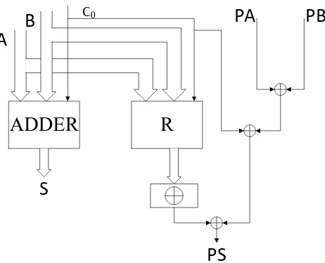
For addition function, parity-prediction function is quite complicate. Assuming two inputs are A and B. The parity codes for inputs are PA and PB. The output is S. The parity code for output is PS. The output bit si is equal to ai ⊕bi⊕ci−1. Considering
modulo2 addition, the output parity is given by the expression
ˆ PS =
n−1 X
i=0 si =
n−1 X
i=0
(ai⊕bi⊕ci−1) =
n−1 X
i=0 ai⊕
n−1 X
i=0 bi⊕
n−1 X
i=0
ci−1 =PA⊕PB⊕ n−1 X
i=0
ci−1(2.6)
where ci−1 is the carry input of bit i.
In a system using parity encoded data, the parities PA and PB are already available.
ADDER
R
A
B
C0
PA
PB
PS
S
Figure 2.3: Parity prediction adder.
The most straightforward approach is to duplicate the carry-generate circuits. Figure 2.3 depicts the structure of parity prediction adder. The block R implements the du-plicated carries. This duplication is essential to prevent the situation that errors affect both the predicted parity ˆPS and the resultS. However, the duplicated carries make the
overhead of the system unacceptable especially for fast adders such as carry look-ahead adders.
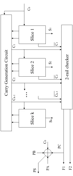
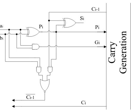
An advanced architecture of carry checking/parity prediction adders is presented in [72]. Three main measures in this architecture are removing the parity generator, avoiding duplication of complex carry generation blocks, and using partial carry duplication. Fig-ure 2.4 shows the carry checking/parity prediction adder avoiding duplication of the carry generation block and the architecture of adder bit slice using partial carry duplication.
F1 and F2 in Figure 2.4 are two outputs of the double-rail checker. Because of the property of double-rail checkers that they have a one-to-one correspondence with the parity trees, double-rail checkers can be viewed as parity generators with double-rail inputs and outputs. The inputs to the double-rail checker are Ci and ¯Ci, so the output
F1 isPC. PS can be obtained by makingPA, PB, PC, andC0 going through an XOR gate.
[image:31.595.185.416.76.263.2]2.4 Proposed Approach 23
C
ar
ry
G
en
er
at
io
n
C
ir
cu
it
S
li
ce
k
S
li
ce
2
S
li
ce
1
2
-r
ai
l
ch
ec
k
er
P B C 0 P C PS PA F1 F2
S k
..
.
S 2 S 1 C 0 C 1 C 2 C k-1 Ck
-1
C
2
C
1
[image:32.595.167.419.94.698.2]Pi
ai
bi
Ci-1
Pi
Si
Gi
Ci
Ci-1
C
ar
ry
G
en
er
at
io
n
Figure 2.5: Adder bit slice using partial carry duplication.
hardware cost and using the carry inputs from the normal carry generation logic rather than the previous slice of the check carries to guarantee high speed.
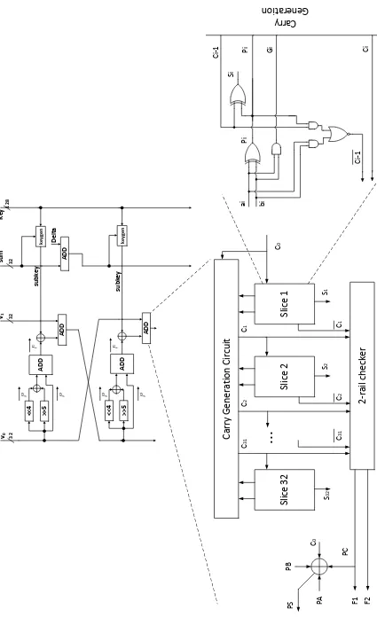
[image:33.595.180.400.79.267.2]2.4 Proposed Approach 25 Pi ai bi Ci -1 Pi Si Gi Ci Ci -1 Carry Generation
Carry Generation Circuit
Slice 32 Slice 2 Slice 1 2-rail checker PB C 0 PC
PS PA F1
S 32
...
S 2 S 1 C 0 C 1 C 2 C 31 C 31 C 2 C 1 << 4 >> 5 ADD ADD AD D ke yg e n << 4 >> 5 ADD ADD ke yg en 32 32 32 128 v0 v1 su m subkey Key Delta subkey F2 [image:34.595.87.512.77.773.2]2.4.2
Recomputing with Rotated Operands (RERO)
Concurrent error detection is an appealing error detection technique because it can detect errors with performing the normal operations of the system at the same time. Redun-dancy is an essential part of the error detection method. Hardware redunRedun-dancy and time redundancy are two general forms of redundancy.
• Hardware redundancy relies on duplication of the hardware for operations, and comparison of the results obtained by two separate hardware will allow error detec-tion.
• Time redundancy will reduce the hardware cost at the expense of using extra time. It will redo the operation in a different way to allow errors to be detected. During the first computation step, the normal operands are applied. In the recomputation step, the operands are encoded and correct results can be generated after decoding. The mismatch of the two results indicates an error. In many applications where time is not critical, time redundancy is a good solution, because additional time is more affordable than extra hardware, and time redundancy has no impact on phys-ical weight, size or power consumption. Therefore, time redundancy is currently received much attention.
2.4 Proposed Approach 27
bits. As k becomes larger, a considerable increase of space and time complexity occurs. and the error probability in the ALU increases also.
Error detection schemes based on time redundancy often suffer from the inability to detect permanent faults. RERO (Recomputing with Rotated Operands) is a technique for concurrent error detection introduced for arithmetic units which is capable of detecting not only the transient faults which are common in fault attacks but also the permanent faults affecting logic gates in the cryptographic hardware and embedded systems. Suppose ψ andψ−1 are n-bit rotations (or cyclic shifts) toward the least and most significant bits of a binary operand, respectively. Moreover, let π be the input to an arithmetic function g, and g(π) be its output in such a way that ψ−1(g(ψ(π))) = g(π). To apply the RERO
method, we need to store the result of the first computation (first run) and compare it against the result of the second computation (second run). If the results are different, it indicates an error is alerted by the error indication flag. The logic pattern before rotation is shown below:
n−1 n−2 · · · i+ 1 i · · · 2 1 0,
and the logic pattern after rotation is:
i · · · 2 1 0 n−1 n−2 · · · i+ 1.
RERO for logic gates is quite straightforward. The most involved part for RERO is the one for addition. The correctness of carry-in for logic bit i+ 1th and carry-out from logic bit n−1th should be guaranteed. As such, two measures are taken to solve the carry-in and carry-out problem for RERO; one extra bit is added as the most significant bit and the logic pattern before rotation becomes:
and the logic pattern after rotation becomes:
i · · · 2 1 0 @ n−1 n−2 · · · i+ 1,
where @ is the added bit. The values of this bit are always “0”. As such, no carry-out transfers from bit @ to bit 0th. Thus, logic bit n−1th is not able to affect logic bit 0th. Moreover, one needs to link the carry-out from the most significant bit to the carry-in of bit 0th. Due to the fact that the values of the extra bit are always “0”, the carry-out from the most significant bit is “0” in the first computation and it will not affect bit 0th. During the second computation, the most significant bit contains logic bitith. The carry-out from logic bit ith is applied to the carry-in of logic bit i+ 1th.
2.4.2.1 Throughput and Efficiency Considerations
Time redundancy techniques suffer from degradations in performance. However, it is possible to increase the frequency of computations (and thus to increase the efficiency and throughput) through sub-pipelining. This can be performed based on the resources available and the performance boost required. Suppose one pipeline-register has been placed to sub-pipeline the structures. The location for placing the registers is chosen to break the timing path in to approximately equal halves. Let us denote the two halves of pipelined stages by Π1 and Π2. The original input is first applied to the architecture in
the first cycle. In the second cycle, while the second half of the circuit (Π2) executes this
first input, the rotated variant of the first input is fed to the first half of the circuit (Π1).
This trend is consecutively executed until the last rotated input is derived. We note that for detecting the errors, the outputs of the runs with the rotated-inputs are rotated back and compared against the original inputs. Therefore, any mismatch indicates an error.
2.5 False-Alarm Explorations 29
time-redundancy schemes which introduce much more overall design overhead. Time-redundancy techniques inherently tend to increase the number of cycles needed for com-putations. This reduces the throughput of the hardware implementations accordingly. Therefore, in our proposed approach, by introducing sub-pipelining, we increase the fre-quency of the clock to make sure the design throughput is acceptable compared to the original architecture.
2.5
False-Alarm Explorations
We would like to emphasize that the false-alarm immunity of such crypto-systems also determines the immunity against the attacks intending to induce distrust to users. Such malicious intents might try to divert the fault diagnosis stream so that without having errors at the output of the crypto-architectures used in smart infrastructures, alarms get falsely initiated which would eventually cause abandoning the entire system. For instance, in an implantable medical device, one could receive such false-alarms, warning the existence of a defect or attack in the embedded hardware systems within the device. This false-alarm can cause much discomfort and a potential replacement of the medical device which could be either impossible or vitally dangerous. In short, protecting against such cases would result in reliable and false-alarm immune smart infrastructures that are trustworthy and can be used safely for different usage models.
Error Simulations
To evaluate the error detection capability of the proposed structures, fault-injection sim-ulations have been performed. The fault model used is elaborated in the following.
3.1
Fault Model
Throughout this thesis, both single and multiple stuck-at faults have been considered (note that these could be transient or permanent). These two models cover both malicious fault attacks and natural faults. Indeed, single stuck-at faults model the natural failures (such as single event upsets) and are the ideal cases for the attackers. However, due to technological constraints, single stuck-at fault injections become more difficult for an attacker to gain information (it is still a possibility due to larger components such as bus-lines). Thus, multiple bits will actually be flipped, and, thus, multiple stuck-at faults are also considered in this thesis.
3.2
Simulation Results
3.2 Simulation Results 31
but the combination of parity bits if the fault model is multiple, randomly-distributed faults (permanent or transient) can detect with higher rate. One side-note is that through testing, permanent faults can be detected as well but transient faults (in case they are randomly-distributed) can be detected with high ratio using the proposed methods. We note that, however, even a half-round has a number of parities so theoretically, the detection rate is much higher even for half-round localized faults affecting the blocks covered by the respective parities. 10,000 faults are injected using eight different test cases and validated for error coverage and assessed through a linear-feedback shift register (LFSR)-based simulation environment. It is noted that we use Fibonacci implementation LFSRs with the required output taps for injecting random multiple errors, where the numbers, locations, and types of the errors are randomly chosen.
For each injection, error indication flags are monitored, and the detected errors are counted. The results of the performed simulations show very high error coverage (all the cases have at least 9,996 faults detected out of 10,000 samples, i.e., 99.96% detection rate for this case). For the signature-based scheme, multiple parities for multiple detection points are used to achieve such high coverage as single parities are ineffective even for single errors. It is noted that the implemented architecture utilizes the RERO method for one computation of a round to have a practical scheme.
FPGA Implementations
In this chapter, we present the results of the overhead assessments using the FPGA hardware platforms. The analysis has been performed for the original and the error de-tection structures of the encryption process of the XTEA. Vivado version 2013.2 and Kintex FPGA device xc7k70tlfbg676-2L have been utilized for the FPGA implementa-tions. VHDL has been used as the design entry for the original and the error detection structures.
To benchmark the performance of the proposed schemes, we have done implementa-tions for the original and fault diagnosis schemes as seen in Table 4.1. Moreover, based on the sub-pipelining approach presented in this thesis, one can alleviate the inherent performance degradations of the RERO method. Specifically, with the expense of adding registers for deep sub-pipelining (for instance, one stage sub-pipelining in Table 4.1), higher frequencies are achieved for the RERO scheme which make the degradations in throughput less intense.
33
Table 4.1: Performance degradations of the proposed schemes.
Structure Delay (ns) Overhead Throu. (Mbps) Deg.
Original 3.833 - 39.57
-Parity Prediction 4.913 28.2% 28.69 27.5%
RERO1 2.891 - 26.42 33.2%
1. One stage sub-pipelined architecture.
Table 4.2: Area and power consumption overheads of the proposed schemes.
Structure Area (#slices) Overhead Power (mW) Overhead
Original 177 - 87
-Parity-based 203 14.7% 92 5.7%
RERO 228 28.8% 91 4.6%
architectures.
In Table 4.2, the area and power consumptions for the original and the error detection structures of the XTEA are presented. The area of the FPGA implementations are presented in terms of the number of occupied slices and the total power consumptions (working frequency of 100MHz) are derived using Vivado version 2013.2 and Kintex FPGA device xc7k70tlfbg676-2L.
Insights and Discussions
Smart infrastructures such as implantable and wearable medical devices need to transfer data securely as the information transferred is often sensitive and private. The fact that these structures often perform sensitive and in some cases life-saving tasks makes it extremely attractive for the malicious attackers to attack to gain information. In this regard, security mechanisms (such as lightweight block ciphers providing confidentiality to the sensitive data) are crucial.
The proposed approaches in this thesis are much suitable to provide fault immunity and reliability to smart infrastructures (these not only include natural faults but also malicious faults aiming at compromising the entire system). Through the proposed ar-chitectures, such cases are detected and, consequently, warn the users of security systems so that later precautions are provided. We have proposed a framework which can be tailored based on the objectives in terms of reliability and fault immunity and can be used to detect various faults with different fault models provided.
Chapter 6
Conclusions
XTEA Algorithm in Verilog
module x t e a ( c l o c k , r e s e t , mode , data_in1 , data_in2 , key_in , data_out1 , data_out2 , a l l _ d o n e ) ;
Parameter s 0 = 8 ’ d0 , s 1 = 8 ’ d1 , s 2 = 8 ’ d2 , s 3 = 8 ’ d3 , s 4 = 8 ’ d4 , s 5 = 8 ’ d5 , s 6 = 8 ’ d6 , s 7 = 8 ’ d7 , s 8 = 8 ’ d8 , s 9 = 8 ’ d9 , s 1 0 = 8 ’ d10 , s 1 1 = 8 ’ d11 , s 1 2 = 8 ’ d12 , s 1 3 = 8 ’ d13 , s 1 4 = 8 ’ d14 , s 1 5 = 8 ’ d15 , s 1 6 = 8 ’ d16 , s 1 7 = 8 ’ d17 ;
i n p u t c l o c k , r e s e t , mode ;
i n p u t [ 3 1 : 0 ] data_in1 , data_in2 ; i n p u t [ 1 2 7 : 0 ] key_in ;
o u t p u t [ 3 1 : 0 ] data_out1 , data_out2 ; o u t p u t a l l _ d o n e ;
w i r e c l o c k , r e s e t ;
w i r e [ 3 1 : 0 ] data_in1 , data_in2 ; w i r e [ 1 2 7 : 0 ] key_in ;
37
r e g [ 7 : 0 ] s t a t e ; r e g [ 7 : 0 ] x ;
r e g [ 3 1 : 0 ] data_out1 , data_out2 , sum , workunit1 , workunit2 , d e l t a ;
a l w a y s @( p o s e d g e c l o c k o r p o s e d g e r e s e t ) b e g i n
i f ( r e s e t )
// r e s e t s t a t e s t a t e = s 0 ; e l s e b e g i n
c a s e ( s t a t e )
s 0 : s t a t e = s 1 ; s 1 : s t a t e = s 2 ; s 2 : s t a t e = s 3 ;
s 3 : s t a t e = w h i l e _ f l a g ? s 4 : s 1 4 ; s 4 : s t a t e = modereg ? s 1 0 : s 5 ; s 5 : s t a t e = s 6 ;
s 1 7 : s t a t e = s 1 7 ;
d e f a u l t : s t a t e = 4 ’ bxxxx ; e n d c a s e
end end
a l w a y s @( p o s e d g e c l o c k o r p o s e d g e r e s e t ) b e g i n
i f ( r e s e t ) b e g i n
// r e s e t a l l our o u t p u t s and r e g i s t e r s data_out1 = 3 2 ’ h00000000 ;
data_out2 = 3 2 ’ h00000000 ; x = 8 ’ b00000000 ;
sum = 3 2 ’ h00000000 ; w h i l e _ f l a g = 1 ’ b0 ;
w o r k u n i t 1 = 3 2 ’ h00000000 ; w o r k u n i t 2 = 3 2 ’ h00000000 ;
s e l e c t s l i c e = 1 ’ b0 ; a l l _ d o n e = 1 ’ b0 ;
d e l t a = 3 2 ’ h00000000 ; modereg = 1 ’ b0 ;
end
e l s e b e g i n
c a s e ( s t a t e )
s 1 : b e g i n
// s t o r e i n p u t v a l u e s t o r e g i s t e r s i n c a s e they ’ r e not s t a b l e
39
d e l t a = 3 2 ’ h9E3779B9 ; sum = 3 2 ’ h c 6 e f 3 7 2 0 ;
modereg = mode ; end
s 2 : i f ( x < 8 ’ d32 ) w h i l e _ f l a g = 1 ’ b1 ; e l s e w h i l e _ f l a g = 1 ’ b0 ;
s 3 : b e g i n
// This n u l l s t a t e was n e c e s s a r y t o f i x a t i m i n g i s s u e .
// s 2 s e t s w h i l e _ f l a g and p r e v i o u s l y t h e c o n t r o l path r e a d i t i n t h e same s t a t e
/ / ( but i n t h e n e x t c l o c k c y c l e ) , however t h e r e g wasn ’ t s e t when we t r i e d t o
// r e a d i t , s o t h i s s t a t e was
i n s e r t e d t o add a d e l a y . This was when r u n n i n g @25MHz .
//FIXME : t h e r e ’ s g o t t o be a b e t t e r s o l u t i o n t o t h i s . . .
end s 4 : b e g i n
// This s t a t e d o e s n o t h i n g i n t h e dat a path ; i t ’ s used f o r an i f s t a t e m e n t i n t h e
// c o n t r o l path . end
s 5 : s e l e c t s l i c e = ( sum >> 3 2 ’ d11 & 3 2 ’ d3 ) ;
s 6 : c a s e ( s e l e c t s l i c e )
2 ’ b00 : w o r k u n i t 2 = w o r k u n i t 2 −
( ( ( w o r k u n i t 1 << 4 ^ w o r k u n i t 1 >> 5 ) + w o r k u n i t 1 ) ^ ( sum + key_in [ 1 2 7 : 9 6 ] ) ) ;
2 ’ b01 : w o r k u n i t 2 = w o r k u n i t 2 − ( ( ( w o r k u n i t 1 << 4 ^ w o r k u n i t 1 >>
5 ) + w o r k u n i t 1 ) ^ ( sum + key_in [ 9 5 : 6 4 ] ) ) ;
2 ’ b10 : w o r k u n i t 2 = w o r k u n i t 2 − ( ( ( w o r k u n i t 1 << 4 ^ w o r k u n i t 1 >>
5 ) + w o r k u n i t 1 ) ^ ( sum + key_in [ 6 3 : 3 2 ] ) ) ;
2 ’ b11 : w o r k u n i t 2 = w o r k u n i t 2 − ( ( ( w o r k u n i t 1 << 4 ^ w o r k u n i t 1 >>
5 ) + w o r k u n i t 1 ) ^ ( sum + key_in [ 3 1 : 0 ] ) ) ;
d e f a u l t : w o r k u n i t 2 = 3 2 ’
b z z z z z z z z z z z z z z z z z z z z z z z z z z z z z z z z ;
e n d c a s e
s 7 : sum = sum − d e l t a ;
41
s 9 : b e g i n
c a s e ( s e l e c t s l i c e )
2 ’ b00 : w o r k u n i t 1 = w o r k u n i t 1 − ( ( ( w o r k u n i t 2 << 4 ^ w o r k u n i t 2 >> 5 ) + w o r k u n i t 2 ) ^ ( sum +
key_in [ 1 2 7 : 9 6 ] ) ) ;
2 ’ b01 : w o r k u n i t 1 = w o r k u n i t 1 − ( ( ( w o r k u n i t 2 << 4 ^ w o r k u n i t 2 >> 5 ) + w o r k u n i t 2 )
^ ( sum + key_in [ 9 5 : 6 4 ] ) ) ;
2 ’ b10 : w o r k u n i t 1 = w o r k u n i t 1
− ( ( ( w o r k u n i t 2 << 4 ^ w o r k u n i t 2 >> 5 ) +
w o r k u n i t 2 ) ^ ( sum + key_in [ 6 3 : 3 2 ] ) ) ;
2 ’ b11 : w o r k u n i t 1 = w o r k u n i t 1 − ( ( ( w o r k u n i t 2 << 4 ^ w o r k u n i t 2 >> 5 ) + w o r k u n i t 2 ) ^ ( sum + key_in [ 3 1 : 0 ] ) ) ;
d e f a u l t : w o r k u n i t 1 = 3 2 ’
b z z z z z z z z z z z z z z z z z z z z z z z z z z z z z z z z ; e n d c a s e
x = x + 1 ’ b1 ; end
/∗ S t a t e s 10−14 used f o r e n c i p h e r o p e r a t i o n s ∗/
s 1 0 : s e l e c t s l i c e = ( sum & 3 2 ’ d3 ) ; s 1 1 : c a s e ( s e l e c t s l i c e )
2 ’ b00 : w o r k u n i t 1 = w o r k u n i t 1 + ( ( ( w o r k u n i t 2 << 4 ^ w o r k u n i t 2 >> 5 ) + w o r k u n i t 2 ) ^ ( sum + key_in [ 1 2 7 : 9 6 ] ) ) ;
2 ’ b01 :
w o r k u n i t 2 >> 5 ) + w o r k u n i t 2 ) ^ ( sum + key_in [ 9 5 : 6 4 ] ) ) ;
2 ’ b10 : w o r k u n i t 1 = w o r k u n i t 1 + ( ( ( w o r k u n i t 2 << 4 ^ w o r k u n i t 2 >> 5 ) + w o r k u n i t 2 ) ^ ( sum +
key_in [ 6 3 : 3 2 ] ) ) ;
2 ’ b11 : w o r k u n i t 1 = w o r k u n i t 1 + ( ( ( w o r k u n i t 2 << 4 ^ w o r k u n i t 2 >> 5 ) + w o r k u n i t 2 ) ^ ( sum + key_in [ 3 1 : 0 ] ) ) ;
d e f a u l t : w o r k u n i t 1 = 3 2 ’
b z z z z z z z z z z z z z z z z z z z z z z z z z z z z z z z z ; e n d c a s e
s 1 2 : sum = sum + d e l t a ;
s 1 3 : s e l e c t s l i c e = ( sum >> 3 2 ’ d11 & 3 2 ’ d3 ) ; s 1 4 : b e g i n
c a s e ( s e l e c t s l i c e )
2 ’ b00 : w o r k u n i t 2 = w o r k u n i t 2 + ( ( ( w o r k u n i t 1 << 4 ^ w o r k u n i t 1 >> 5 ) + w o r k u n i t 1 ) ^ ( sum + key_in
[ 1 2 7 : 9 6 ] ) ) ; 2 ’
b01 : w o r k u n i t 2 = w o r k u n i t 2 + ( ( ( w o r k u n i t 1 << 4 ^ w o r k u n i t 1 >> 5 ) + w o r k u n i t 1 ) ^ ( sum +
key_in [ 9 5 : 6 4 ] ) ) ;
2 ’ b10 : w o r k u n i t 2 = w o r k u n i t 2 + ( ( ( w o r k u n i t 1 << 4 ^ w o r k u n i t 1 >> 5 ) + w o r k u n i t 1 ) ^ ( sum + key_in
[ 6 3 : 3 2 ] ) ) ; 2 ’ b11
43
d e f a u l t : w o r k u n i t 2 = 3 2 ’
b z z z z z z z z z z z z z z z z z z z z z z z z z z z z z z z z ; e n d c a s e
x = x + 1 ’ b1 ; end
s 1 5 : b e g i n
// This s t a t e was added t o f i x a t i m i n g i s s u e .
//Same i s s u e a s above − t r y i n g t o r e a d w o r k u n i t 1 & w o r k u n i t 2 b e f o r e they ’ ve s e t t l e d . end
s 1 6 : b e g i n
// s e t t h e o u t p u t s t o t h e working r e g i s t e r s
data_out1 = w o r k u n i t 1 ; data_out2 = w o r k u n i t 2 ; end
s 1 7 : a l l _ d o n e = 1 ’ b1 ; d e f a u l t : b e g i n
data_out1 = 3 2 ’
b z z z z z z z z z z z z z z z z z z z z z z z z z z z z z z z z ;
data_out2 = 3 2 ’
b z z z z z z z z z z z z z z z z z z z z z z z z z z z z z z z z ;
end e n d c a s e
end
References
[1] H. Cheng and Q. Ding, “Overview of the Block Cipher,” in Proc. 2012 Second In-ternational Conference on Instrumentation & Measurement, Computer,
Communi-cation and Control, 2012, pp. 1628–1631.
[2] M. Akkar and C. Giraud, “An Implementation of DES and AES, Secure against Some Attacks,” inProc. of the Workshop on Cryptographic Hardware and Embedded
Systems (CHES2001), May 2001, pp. 315–325.
[3] C. Sanchez-Avila and R. Sanchez-Reillol, “The Rijndael block cipher (AES proposal) : a comparison with DES,” IEEE 35th International Carnahan Conference on
Secu-rity Technology, pp. 229–234, Oct. 2001.
[4] R. Roman, P. Najera, and J. Lopez, “Securing the Internet of Things,” Computer, vol. 44, no. 9, pp. 51–58, Sep. 2011.
[5] National Institute of Standards and Technologies, “Announcing the Advanced En-cryption Standard (AES),” Federal Information Processing Standards Publication, no. 197, Nov. 2001.
[6] D. Wheeler and R. Needham, “TEA, a tiny encryption algorithm,” in Proc. Fast
Software Encryption, 1995, pp. 363–366.
[7] G. Leander, C. Paar, A. Poschmann, and K. Schramm, “New Lightweight DES Variants,” in Proc. of Fast Software Encryption, vol. 4593, Mar. 2007, pp. 196–210.
block cipher suitable for low-resource device,” inProc. Cryptographic Hardware and
Embedded Systems, vol. 4249, Oct. 2006, pp. 46–59.
[9] C. H. Lim and T. Korkishko, “mCrypton - A Lightweight Block Cipher for Security of Low-Cost RFID Tags and Sensors,” Information Security Applications, vol. 3786, pp. 243–258, Aug. 2005.
[10] A. Bogdanov, L. Knudsen, G. Leander, C. Paar, A. Poschmann, M. J. B. Robshaw, Y. Seurin, and C. Vikkelsoe, “PRESENT: An Ultra-Lightweight Block Cipher,” in
Proc. Cryptographic Hardware and Embedded Systems, vol. 4727, Sep. 2007.
[11] C. Canniere, O. Dunkelman, and M. Knezevic, “Katan and ktantan - a family of small and effcient hardware-oriented block ciphers,” inProc. Cryptographic Hardware
and Embedded Systems, vol. 459, Sep. 2009, pp. 272–288.
[12] J. . Borgho, A. Canteaut, T. Guneysu, S. Thomsen, and T. Yalcin, “PrincešCa low-latency block cipher for pervasive computing applications,” in Proc. Advances in
Cryptology, vol. 7658, Dec. 2012, pp. 208–225.
[13] T. Suzaki, K. Minematsu, S. Morioka, and E. Kobayashi, “TWINE: Lightweight Block Cipher for Multiple Platforms,” in Proc. Selected Areas in Cryptography, vol. 7707, Aug. 2013, pp. 339–354.
[14] S. Ojha, N. Kumar, K. Jain, and S.Lal, “TWIS - A Lightweight Block Cipher,”
Information Systems Security, vol. 5905, pp. 280–291, Dec. 2009.
[15] D. Wheeler and R. Needham, “TEA extensions,” Cambridge University, England, Technical report, Oct. 1997.
[16] S. Jana, J. Bhaumik, and M. K. Maiti, “Survey on lightweight block cipher,”
In-ternational Journal of Soft Computing and Engineering, vol. 3, pp. 183–187, Nov.
2013.
References 47
CAST, DES-X, newDES, RC2, and TEA,”Information and Communications Secu-rity, pp. 233–246, 1997.
[18] S. Srinivasan, “FLAW: FPGA lifetime awareness,” in Design Automation Confer-ence, 2006, pp. 630–635.
[19] C. GušŠrin, V. Huard, and A. Bravaix, “The energy-driven hot-carrier degradation modes of nMOSFETs,” IEEE Trans. Device and Materials Reliability, vol. 7, no. 2, pp. 225–235, Jun. 2007.
[20] D. K. Schroder and J. A. Babcock, “Negative bias temperature instability: Road to cross in deep submicron silicon semiconductor manufacturing,” Journal of Applied
Physics, vol. 94, no. 1, pp. 1–18, Jul. 2003.
[21] P. J. Clarke, A. K. Ray, and C. A. Hogarth, “Electromigration-a tutorial introduc-tion,” Int. Journal of Electronics, vol. 69, no. 3, pp. 333–338, Feb. 1990.
[22] D. Esseni, J. D. Bude, and L. Selmi, “On interface and oxide degradation in VLSI MOSFETs-part I: Deuterium effect in che stress regime,” IEEE Trans. Electron
Devices, vol. 49, no. 2, pp. 247–253, Feb. 2002.
[23] D. Esseni, J. D. Bude, and L. Selmi, “On interface and oxide degradation in VLSI MOSFETs-part II: Fowler-nordheim stress regime,” IEEE Trans. Electron Devices, vol. 59, no. 2, pp. 254–263, Feb. 2002.
[24] I. G. Harris and R. Tessier, “Testing and diagnosis of interconnect faults in cluster-based FPGA architectures,”IEEE Trans. Comput.-Aided Des. Integr. Circuits Syst., vol. 21, no. 11, pp. 1337–1343, Nov. 2002.
[25] M. Berg, “Fault tolerance implementation within SRAM based FPGA designs based upon the increased level of single event upset susceptibility,” in Proc. IEEE Int.
On-Line Testing Symp. (IOLTS’06), 2006.
with shifted operands,” IEEE Trans. Comput., vol. C-31, no. 7, pp. 589–595, Jul. 1982.
[27] J. Li and E. E. Swartzlander, “Concurrent error detection in ALUs by recomputing with rotated operands,” inProc. IEEE Int. Workshop on Defect and Fault Tolerance
in VLSI Systems, Nov. 1992, pp. 109–116.
[28] S. Durand, C. Piguet, and C. suisse, “FPGA with selfrepair capabilities,” in Proc.
Int. Workshop on Field Programmable Gate Arrays, 1994, pp. 1–6.
[29] C. Stroud, S. Konala, P. Chen, and M. Abramovici, “Built-in self-test of logic blocks in FPGAs,” in Proc. VLSI Test Symp., 1996, pp. 387–392.
[30] S.-K. Lu and C.-Y. Chen, “Fault detection and fault diagnosis techniques for lookup table FPGAs,” in Proc. Asian Test Symp. (ATS’02), vol. 15, no. 1, 2002, pp. 397– 406.
[31] A. Alaghi, M. S. Yarandi, and Z. Navabi, “An optimum ORA BIST for multiple fault FPGA look-up table testing,” in Proc. Asian Test Symp. (ATS’06), 2006, pp. 293–298.
[32] J. Smith, T. Xia, and C. Stroud, “An automated BIST architecture for testing and diagnosing FPGA interconnect faults,” Journal of Electronic Testing: Theory and
Applications, vol. 22, no. 3, pp. 239–253, Jun. 2006.
[33] I. G. Harris and R. Tessier, “Diagnosis of interconnect faults in cluster-based FPGA architectures,” in Proc. Int. Conf. Computer Aided Design, 2000, pp. 472–475.
[34] M. Abramovici, J. M. Emmert, and C. E. Stroud, “Roving stars: An integrated approach to on-line testing, diagnosis, and fault tolerance for FPGAs in adaptive computing systems,” in Proc. NASA/DoD Workshop on Evolvable Hardware, 2001, pp. 73–92.
References 49
logic blocks,” IEEE Trans. Very Large Scale Integration (VLSI) Systems, vol. 15, no. 2, pp. 216–226, Feb. 2007.
[36] N. R. Shnidman, W. H. Mangione-Smith, and M. Potkonjak, “On-line fault detec-tion for bus-based field programmable gate arrays,” IEEE Trans. Very Large Scale
Integration (VLSI) Systems, vol. 6, no. 4, pp. 656–667, Dec. 1998.
[37] B. Girau and A. Tisserand, “On-line arithmetic-based reprogrammable hardware implementation of multilayer perceptron back-propagation,” inProc. of MicroNeuro ’96, 1996, pp. 168–175.
[38] A. Tisserand and M. Dimmler, “FPGA implementation of real-time digial controllers using on-line arithmetic,” in Proc. Int. Workshop on Field-programmable Logic and
Applications, Sep. 1997, pp. 472–481.
[39] A. Tenca and M. D. Ercegovac, “A variable long-precision arithmetic unit design for reconfigurable coprocessor architectures,” in IEEE Symp. FPGAs for Custom
Computing Machines, 1998, pp. 216–225.
[40] A. Tisserand, P. Marchal, and C. Piguet, “An on-line arithmetic based FPGA for low power custom computing,” inProc. Int. Workshop on Field Programmable Logic
and Applications, 1999, pp. 264–273.
[41] E. Mosanya and E. Sanchez, “A FPGA-based hardware implementation of general-ized profile search using online arithmetic,” inProc. AGM/SIGDA Int. Symp. Field
Programmable Gate Arrays, 1999, pp. 101–111.
[42] D. Lau, A. Schneider, M. D. Ercegovac, and J. Villasenor, “FPGA-based structures for on-line FFT and DCT,” inProc. IEEE Symp. Field-programmable Custom
Com-puting Machines, 1999, pp. 310–311.
[44] J. Chen, M. Wang, and B. Preneel, “Impossible differential cryptanalysis of the lightweight block ciphers TEA, XTEA and HIGHT,” inProc. Progress in
Cryptology-AFRICACRYPT, 2012, pp. 117–137.
[45] Y. Sasaki, L. Wang, Y. Sakai, K. Sakiyama, and K. Ohta, “Three-subset meet-in-the-middle attack on reduced XTEA,” inProc. Progress in Cryptology-AFRICACRYPT, 2012, pp. 138–154.
[46] Xilinx. [Online]. Available: http://www.xilinx.com
[47] P. C. Kocher, “Timing attacks on implementations of Diffie-Hellman, RSA, DSS, and other systems,” in Advances in Cryptology–CRYPTO ’96, 1996.
[48] P. C. Kocher, J. Jaffe, and B. Jun, “Differential power analysis,” in Advances in
Cryptology–CRYPTO ’99, 1999.
[49] J.-J. Quisquater and D. Samyde, “Electromagnetic analysis (EMA) measures and countermeasures for smart cards,” E-Smart Smartcard Programming and Security, vol. 2140, pp. 200–210, 2001.
[50] J. R. Rao and P. Rohatgi. Empowering side-channel attacks. [Online]. Available:
http://eprint.iacr.org/2001/037/
[51] K. Gandolfi, C. Mourtel, and F. Olivier, “Electromagnetic analysis: Concrete re-sults,” in Proc. Cryptographic Hardware and Embedded Systems, vol. 2162, 2001, pp. 251–272.
[52] A. Shamir and E. Tromer. Acoustic cryptanalysis – on nosy people and noisy machines. [Online]. Available: http://cs.tau.ac.il/~tromer/acoustic/ec04rump/
[53] O. Kocar, “Hardwaresicherheit von mikrochips in chipkarten,” Datenschutz und
Datensicherheit, no. 7, pp. 421–424, 1996.
References 51
[55] H. Handschuh, P. Paillier, and J. Stern, “Probing attacks on tamper-resistant de-vices,” inProc. Cryptographic Hardware and Embedded Systems, vol. 1717, 1999, pp. 303–315.
[56] D. Boneh, R. DeMillo, and R. Lipton, “On the importance of checking cryptographic protocols for faults,” in Proc. Int. Conf. Eurocrypt, 1997, pp. 37–51.
[57] M. Mozaffari Kermani and A. Reyhani-Masoleh, “Concurrent structure-independent fault detection schemes for the Advanced Encryption Standard,”IEEE Trans. Com-put., vol. 59, no. 5, pp. 608–622, May 2010.
[58] C. H. Yen and B. F. Wu, “Simple error detection methods for hardware implemen-tation of Advanced Encryption Standard,” IEEE Trans. Comput., vol. 55, no. 6, pp. 720–731, Jun. 2006.
[59] M. Mozaffari Kermani and A. Reyhani-Masoleh, “Reliable hardware architectures for the third-round SHA-3 finalist Grostl benchmarked on FPGA platform,” in Proc.
IEEE Int. Symp. Defect and Fault Tolerance in VLSI Systems (DFT), Oct. 2011,
pp. 325–331.
[60] T. G. Malkin, F. X. Standaert, and M. Yung, “A comparative cost/security anal-ysis of fault attack countermeasures,” in Proc. Int. Workshop Fault Diagnosis and
Tolerance in Cryptography, Oct. 2006, pp. 159–172.
[61] M. Mozaffari Kermani and A. Reyhani-Masoleh, “Parity-based fault detection ar-chitecture of S-box for Advanced Encryption Standard,” in Proc. IEEE Int. Symp.
Defect and Fault Tolerance in VLSI Systems (DFT), Oct. 2006, pp. 572–580.
[62] G. D. Natale, M. Doulcier, M. L. Flottes, and B. Rouzeyre, “A reliable architecture for parallel implementations of the Advanced Encryption Standard,” J. Electronic
Testing: Theory and Applications, vol. 25, no. 4, pp. 269–278, Aug. 2009.
Elec-tronic Testing: Theory and Applications (JETTA), vol. 25, no. 4, pp. 225–245, Aug. 2009.
[64] A. Satoh, T. Sugawara, N. Homma, and T. Aoki, “High-performance concurrent error detection scheme for AES hardware,” in Proc. Int. Workshop Cryptographic
Hardware and Embedded Systems, Aug. 2008, pp. 100–112.
[65] M. Mozaffari Kermani and A. Reyhani-Masoleh, “A Lightweight High-Performance Fault Detection Scheme for the Advanced Encryption Standard Using Composite Fields,” IEEE Trans. Very Large Scale Integr. (VLSI) Syst., vol. 19, no. 1, pp. 85– 91, Jan. 2011.
[66] P. Maistri and R. Leveugle, “Double-data-rate computation as a countermeasure against fault analysis,” IEEE Trans. Comput., vol. 57, no. 11, pp. 1528–1539, Nov. 2008.
[67] M. Mozaffari Kermani and A. Reyhani-Masoleh, “A Low-Power High-Performance Concurrent Fault Detection Approach for the Composite Field S-box and Inverse S-box,”IEEE Trans. Comput., vol. 60, no. 9, pp. 1327–1340, Sep. 2011, special issue on Concurrent On-Line Testing and Error/Fault Resilience of Digital Systems.
[68] G. Xiaofei and R. Karri, “Recomputing with permuted operands: A concurrent error detection approach,”IEEE Trans. Computer-Aided Design of Integrated Circuits and
Systems, vol. 32, no. 10, pp. 1595–1608, Oct. 2013.
[69] M. Mozaffari Kermani and R. Azarderakhsh, “Efficient fault diagnosis schemes for re-liable lightweight cryptographic ISO/IEC standard CLEFIA benchmarked on ASIC and FPGA,”IEEE Trans. Ind. Electron., vol. 60, no. 12, pp. 5925–5932, Dec. 2013.
Figure


Related documents
Minors who do not have a valid driver’s license which allows them to operate a motorized vehicle in the state in which they reside will not be permitted to operate a motorized
Intelligent and integrated architectural design can substantially reduce carbon dioxide emissions from energy used in buildings. However, architects need new tools to
HealthLink SmartForms enable a healthcare provider to share structured patient information in real time with any other healthcare provider. This creates significant efficiencies
4.1 The Select Committee is asked to consider the proposed development of the Customer Service Function, the recommended service delivery option and the investment required8. It
Using text mining of first-opinion electronic medical records from seven veterinary practices around the UK, Kaplan-Meier and Cox proportional hazard modelling, we were able to
Furthermore, compared to the eddy current method and the MFL (magnetic flux leakage) method, this sensing system suppresses the noise from lift-off value fluctuation by measuring
• Follow up with your employer each reporting period to ensure your hours are reported on a regular basis?. • Discuss your progress with
The work presented here supports the prevailing view that both CD and IOVD share common cortical loci, although they draw on different sources of visual information, and that
