UNIVERSITI TEKNIKAL MALAYSIA MELAKA
DESIGN OPTIMIZATION USING FINITE ELEMENT
ANALYSIS
This report submitted in accordance with the requirements of the Universiti Teknikal Malaysia Melaka (UTeM) for the Bachelor Degree of Manufacturing Engineering
(Design) with Honours.
By
ABD RAHMAN BIN RAHIM
FACULTY OF MANUFACTURING ENGINEERING
UNIVERSITI TEKNIKAL MALAYSIA MELAKA (UTeM)
BORANG PENGESAHAN STATUS LAPORAN PROJEK SARJANA MUDA
TAJUK:DESIGN OPTIMIZATION USING FINITE ELEMENT ANALYSIS
SESI PENGAJIAN: 2008/2009 Semester 2
Saya ABD RAHMAN BIN RAHIM
mengaku membenarkan Laporan PSM ini disimpan di Perpustakaan Universiti Teknikal Malaysia Melaka (UTeM) dengan syarat-syarat kegunaan seperti berikut:
1. Laporan PSM adalah hak milik Universiti Teknikal Malaysia Melaka dan Penulis. 2. Perpustakaan Universiti Teknikal Malaysia Melaka dibenarkan membuat salinan
untuk tujuan pengajian sahaja dengan izin penulis.
3. Perpustakaan dibenarkan membuat salinan laporan PSM ini sebagai bahan pertukaran antara institusi pengajian tinggi.
4. **Sila tandakan (√)
SULIT
TERHAD
TIDAK TERHAD
(Mengandungi maklumat yang berdarjah keselamatan atau kepentingan Malaysia yang termaktub di dalam AKTA RAHSIA RASMI 1972)
(Mengandungi maklumat TERHAD yang telah ditentukan oleh organisasi/badan di mana penyelidikan dijalankan)
(TANDATANGAN PENULIS)
Alamat Tetap:
KM7 PARIT AMAT JALAN ABDUL RAHMAN 84000, MUAR JOHOR
Tarikh: 21/5/2009
Disahkan oleh:
(TANDATANGAN PENYELIA)
Cop Rasmi:
Tarikh:21/9/2009
DECLARATION
I hereby, declared this report entitled “Preliminary Design Analysis of Hydraulic Transmission” is the results of my own research except as cited in the references.
Signature : ………
APPROVAL
This report submitted to the Faculty of Manufacturing Engineering of UteM as a partial fulfillment of the requirements for the degree of Bachelor of Manufacturing Engineering (Design) with Honours. The member of the supervisory committee is as follow:
………. Project Supervisor
ABSTRACT
DEDICATION
Dedicated to my father, Rahim Bin Yaakob and my mother, Haidah bte Baba.
ACKNOWLEDGEMENTS
I would like to convey my appreciation and indebtedness to those who has been great surprised and helpful for the completion at the project to bring it to success in respect with favorable advice and feasible solution
Thus, I feed comfortably to take this golden opportunity to express my millions of gratitude to my supervisor, Mr Abd Halim Hakim Bin Abd Aziz for his kindly advice and guidance during the project providing tremendous considerately and useful comment and materials to overcome each obstacle I had faced.
Also special thanks to my friends that give me some help during doing this project. Thanks extended to FKP lecturer who had provided technical help and assistance throughout the project.
TABLE OF CONTENTS
Abstract i
Dedication ii
Acknowledgement iii
Table of Content iv
List of Figure v
List of Table vi
List of Abbreviation vii
1. INTRODUCTION 1
1.1
Project Background
1
1.2
Problem Statement
6
1.3
Objectives
7
1.4
Scope of project
7
2. LITERATURE REVIEW 8
2.1
Introduction
8
2.2
History of Bicycle 92.3
What is Bicycle? 142.3.1 Type 15
2.3.2 Performance 16
2.3.3 Frame 17
2.3.4 Brakes 18
2.3.5 Suspension 19
2.3.6 Material of bicycle frame 21
2.4
Material Properties
22
2.5
FEA Solution and Output Data
23
2.6
The Average of Human Weight
24
2.7
Product Planning Process
24
2.8
Identify Customer Needs
26
2.8.1 Customer Satisfaction 27
2.9
Quality Function Deployment (QFD)
28
2.9.1 QFD Overview 29
2.10 Computer Aided Design
30
2.10.1 Element of CAD System 31 2.10.2 CAD software (Solidworks) 31 2.10.3 3D computer graphics 32
2.11
Finite Element Analysis
33
2.11.1 History of the FEA 34 2.11.2 How does finite element analysis work? 36
2.11.3 Processing 36
2.11.4 Analysis (computation of solution) 37
2.11.5 Visualization 37
2.11.6 Application of FEA to the mechanical engineering industry 38 2.11.7 Computer Aided Design and Finite Element Analysis in industries 39 2.11.8 The advantage of FEA 39
3. METHODOLOGY 41
3.1
Introduction
41
3.2
Flow Chart
42
3.3
Phase of Methodology
44
3.3.1 Planning Phase 44
3.3.2 Design Phase 44
3.3.3 Analyze phase 45
3.3.4 Redesign and Optimize Design and Analysis Phase. 45 3.3.5 Preparation of Final Report and Presentation 46
3.4
Conceptual Design (existing bicycle frame)
46
3.4.1 Design1 46
3.4.2 Design 2 47
3.4.3 Design 3 48
3.4.4 Design 4 49
3.5
Data for Bicycle Analysis
51
3.6
Material Properties
52
4. RESULTS AND DISCUSSION 55
4.1 Introduction 55
4.2 Result and Discussion 56
4.2.1 Analysis Design 1 59
4.2.2 Analysis Design 2 63
4.2.3 Analysis Design 3 67
4.2.4 Analysis Design 4 71
4.2.5 Analysis design 5 75
4.3 Identify Best Result 79 4.3 Guideline Data Analysis for New Design 80 4.4 Redesign and Optimization Design Using Finite Element Analysis 85
4.4.1 New Design 86
4.4.1.1 Analysis new design 91
4.4.2 Redesign 1 92
4.4.2.1Analysis Redesign1 97
4.4.3 Redesign 2 98
4.4.3.1 Analysis Redesign2 92
4.4.4 Final Redesign 97
4.4.4.1 Analysis Final Redesign 98
5. CONCLUSION 103
5.1 Conclusion 103
5.2 Recommendation 104
REFERENCES 105
LIST OF FIGURES
1. Figure 1.0: Stages in the design process
2. Figure 1.1: Step Involved in the use of Finite Element Method for solving
a physical problem.
3. Figure 2.1: The steerable Draisienne was invented (Suman Bandrapalli, 2001)
4. Figure 2.2: The MacMillan velocipede was the first of its kind to be
ridden with the legs off the ground. (Suman Bandrapalli, 2001
5. Figure 2.3: The world's first mass-produced riding machine (Bicycling
Popularization Association of Japan, 1999)
6. Figure 2.4: The Phantom, with its ordinary drive, is released (Bicycling Popularization Association of Japan, 1999)
7. Figure 2.5: Ariel, the first model to define the features of the ordinary
bicycle (Bicycling Popularization Association of Japan, 1999)
8. Figure 2.3: The world's first mass-produced riding machine (Bicycling
Popularization Association of Japan, 1999)
9. Figure 2.4: The Phantom, with its ordinary drive, is released (Bicycling Popularization Association of Japan, 1999)
10.Figure 2.5: Ariel, the first model to define the features of the ordinary
bicycle (Bicycling Popularization Association of Japan, 1999)
11.Figure 2.6: The first safety bicycle trial manufactured in Japan (Bicycling
Popularization Association of Japan, 1999)
12.Figure 2.7: Domestic bicycle that was a copy of an English model (Bicycling Popularization Association of Japan, 1999)
13.Figure 2.8: The diagram of bicycle
14.Figure 2.9: The place of brake at bicycle rims.
15.Figure 2.10: Material Properties for Finite Element Model
16.Figure 2.11: Table of average men weight (Steven B. Halls, 2008)
17.Figure 2.12: Table of average women weight (Steven B. Halls, 2008) 18.Figure 2.12: A typical House of Quality matrix
20.Figure 3.1: Flow Chart for PSM Project Flow
21.Figure 3.2: The Isometric Design 1 22.Figure 3.3: The isometric of design 2 23.Figure 3.4: The Isometric of Design 3 24.Figure 3.5: The Isometric of Design 4
25.Figure 3.6: The Isometric of Design 5
26.Figure 3.8: Table of men weight average (Steven B. Halls, 2008) 27.Figure 3.9: Table of Women weight (Steven B. Halls, 2008) 28.Figure 3.10: Material Properties for Finite Element Model 29.Figure 3.11: Gantt Chart 1
30.Figure 3.12: Gantt Chart PSM 2
31.Figure 4.1: Constraint Force, Translational, (Magnitude)
32.Figure 4.2: Displacement Translational, (Magnitude) 33.Figure 4.3: Displacement, Translational (X component) 34.Figure 4.4: Displacement, Translational (Z component 35.Figure 4.5: Stress Tensor (Von Mises)
36.Figure 4.6: Constraint Force, Translational, (Magnitude) 37.Figure 4.7: Displacement Translational, (Magnitude)
38.Figure 4.8: Displacement, Translational (X component) 39.Figure 4.9: Displacement, Translational (Y component) 40.Figure 4.10: Displacement, Translational (Z component) 41.Figure 4.11: Stress Tensor (Von Mises)
42.Figure 4.12: Constraint Force, Translational, (Magnitude)
43.Figure 4.13: Displacement Translational, (Magnitude) 44.Figure 4.13: Displacement, Translational (X component) 45.Figure 4.14: Displacement, Translational (Y component) 46.Figure 4.15: Displacement, Translational (Z component) 47.Figure 4.16: Stress Tensor (Von Mises)
48.Figure 4.17: Constraint Force, Translational, (Magnitude)
54.Figure 4.23: Constraint Force, Translational, (Magnitude)
55.Figure 4.24: Displacement, Translational (Magnitude) 56.Figure 4.25: Displacement, Translational (X component) 57.Figure 4.26: Displacement, Translational (Y component) 58.Figure 4.27: Displacement, Translational (Z component)
59.Figure 4.28: Stress Tensor (Von Mises)
60.Figure 29: Isometric View of New Bicycle Design 61.Figure 4.30: Constraint Force, Translational, (Magnitude) 62.Figure 4.31: Displacement, Translational (Magnitude) 63.Figure 4.32: Displacement, Translational (X component) 64.Figure 4.33: Displacement, Translational (Y component)
65.Figure 4.34: Displacement, Translational (Z component)
66.Figure 4.35: Stress Tensor (Von Mises) 67.Figure 36: Isometric View of Redesign 1
68.Figure 4.37: Constraint Force, Translational, (Magnitude) 69.Figure 4.38: Displacement, Translational (Magnitude) 70.Figure 4.39: Displacement, Translational (X component) 71.Figure 4.40: Displacement, Translational (Y component)
72.Figure 4.41: Displacement, Translational (Z component) 73.Figure 4.42: Stress Tensor (Von Mises)
74.Figure 4.43: Isometric View of Redesign 2
75.Figure 4.44: Constraint Force, Translational (Magnitude)
76.Figure 4.45: Displacement, Translational (Magnitude)
77.Figure 4.46: Displacement, Translational (X component) 78.Figure 4.47: Displacement, Translational (Y component) 79.Figure 4.48: Displacement, Translational (Z component) 80.Figure 4.49: Stress Tensor (Von Mises)
81.Figure 4.50: Isometric View of Final Redesign
82.Figure 4.51: Constraint Force, Translational, (Magnitude)
LIST OF TABLES
1. Table 4.1: Design 1 Analysis Result 2. Table 4.2: Design 2 Analysis Result 3. Table 4.3: Design 3 Analysis Result 4. Table 4.4: Design 4 Analysis Result
5. Table 4.5: Design 5 Analysis Result
6. Table 4.6: Differentiate Between 5 Design from Constraint Force,
Translational (Magnitude)
7. Table4.7: Differentiate Between 5 Design from Displacement
Translational, (Magnitude)
8. Table 4.8: Differentiate Between 5 Design from Displacement Translational, (X Component)
9. Table 4.9: Differentiate Between 5 Design from Displacement
Translational, (Y Component)
10.Table4.10: Differentiate Between 5 Design from Displacement
Translational, (Z Component)
11.Table 4.11: Differentiate Between 5 Design from Stress Tensor (Von Mises)
12.Table 4.13: New Design Analysis Result
13.Table 4.14: The Comparison between Guideline and New Design 14.Table 4.15: Redesign 1 Analysis Result
15.Table 4.16: The Comparison between Guideline and redesign 1
16.Table 4.17: Redesign 2 Analysis Result
17.Table 4.18: The Comparison between Guideline and Redesign 2 18.Table 4.19: Redesign 2 Analysis Result
19.Table 4.20: The Comparison between Guideline and Final Design
CHAPTER 1
INTRODUCTION
1.1
Project Background
Today computer is one of the most important equipment in design and manufacturing
industry. It is also gave an impact more in the industrial sector. Computer is used for
various activities in the industries. However in manufacturing industries it made a very
substantial change in their working. The computer does not only used to simplify many
of the traditional manufacturing tasks but also made it almost impossible for
manufacturing industries to survive in the modern ere without it. Thus it is important for
everyone concerned with the manufacturing industries to learn the use of computer
Among the usages of computer in manufacturing, Computer aided design and Computer
aided manufacturing (CAD/CAM) are by far the best known as well as the best
application. In order to remain competitive in the global economy, it is imperative that
all manufacturing industries adopt CAD/CAM.
In the earlier days of CAD/CAM development the cost used to be prohibitive and did not
allow the small and medium scale industries to adopt it. However, this has changed since
the invention of the microprocessor and the rapid developments taking place in the very
large scale integration (VLSI) of the electronic circuit. The cost of computing equipment
powerful computers. The mass manufacture techniques employed for the manufacture of
computer have further reduced the cost. This has allowed the small and medium scale
companies to use the powerful computers in their day to day operations.
Along with the developments in the hardware, the software, too, continued to develop at
a similar pace. The present day software is easier to use and very powerful, thereby
guaranteeing the result in a much shorter time than was possible earlier. This has
prompted the small and medium scale to enterprises to embrace CAD/CAM in a big way
in the development world. It is, therefore, not uncommon to see even small companies
using CAD or CAM in to improve their productivity.
CAD/CAM is related to the design where design is an activity which needs to be
well-organized and takes into account all influence that are likely to be responsible for the
success of the product under development. A product here means single components,
which is functional in itself like a wrench or an assembly of large number of part or
component all of which will contribute to he functioning of the part such as an
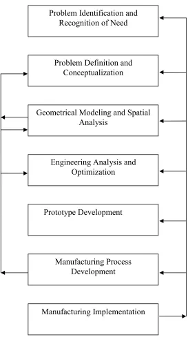
automobile engine. In design, it has stages of the design process. The flow of design
Figure 1.0: Stages in the design process
Problem Identification and Recognition of Need
Geometrical Modeling and Spatial Analysis
Engineering Analysis and Optimization
Prototype Development
Manufacturing Implementation Manufacturing Process
Development Problem Definition and
To design, CAD technology is used. CAD or computer aided design is the use of
computer method to develop the geometric model of the product in the three
dimensional form, such that the geometric and manufacturing requirements can be
examined. Many type of cad software can be use such as SOLIDWORK, CATIA,
INVENTER and other. CATIA software is CAD/CAM family software but it one of the
best CAD software and that suitable for this project. CAD technology is used because
CAD technology can provide the necessary help in the following below:
1. Computer Aided Design (CAD) is faster and more accurate than the conventional
method.
2. The various construction facilities available in CAD would make the job of
developing the model and associated drafting a very easy task.
3. In contrast with the traditional drawing method, under CAD it is possible to
manipulate various dimensions, attributes and distances of the drawing element. This
quality makes CAD useful for design work.
4. Under CAD work will never have to repeat the design or drawing of any component.
Once a component has been made, It can be copied in all further works within
seconds including any geometric transformation need.
5. Modification of a model is very easy and would make the designers task of
improving a given product simple to take care of any future requirement.
6. Use of standard component makes for very fast model development work.
Then for the next process after product design is do an analysis of the product. Where it
is used finite element analysis as a tools. The finite element analysis (FEA) is a very
powerful analysis tool, which can be applied to a range of engineering problem. The
finite element modeling process allowed for discrediting the intricate geometries into
small fundamental volumes called finite element. It is then possible to write the
governing equations and material properties for these elements. These equations are then
assembled by taking proper care of results that describe the behavior of the original
alone but to range of engineering problem such as stress analysis, dynamic analysis, and
deformation studies fluid flow analysis, heat flow analysis and other.
With the FEA software it is possible to try a number of alternative designs before
actually going for a prototype manufacture. The use of FEA tools can converting the
geometry into discretised element and calculating various properties for each element
such as geometry, material properties, constraint and loading. This forms the input for
the analysis. It also can generating the finite element mesh by making a suitable
approximation to the geometry. Then it can calculate the nodes and element properties
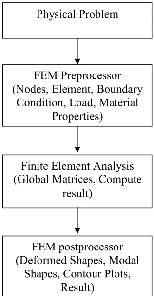
and allowed the material properties to be specified.Under FEA it has steps involved in
the use of finite element method for solving a physical problem. The software used for
[image:19.612.250.408.346.648.2]run this Finite Element Analysis such PATRAN and CATIA.
Figure 1.1: Step Involved in the use of Finite Element Method for solving a physical problem.
Physical Problem
FEM Preprocessor (Nodes, Element, Boundary
Condition, Load, Material Properties)
Finite Element Analysis (Global Matrices, Compute
result)
FEM postprocessor (Deformed Shapes, Modal
Finally, for this PSM project mainly focused on design optimization of bicycle frame
and to proposed the best design and analysis. Bicycle frame is important part in a
bicycle. It is because bicycle frame become a main body or main frame at bicycle. As a
important part at bicycle, bicycle frame must be high strength, tough and durability. It is
because, the body frames usually applied with large force where the force comes from
weight of rider. The bicycle frame usually applied with load around 40kg to 90kg of
people. So for this PSM project focus on design and improve the current bicycle frame
design and do the analysis to the bicycle frame design by using Finite Element Analysis.
Then optimize the design of bicycle frame design by redesign bicycle frame until the get
the best result of analysis. This project tries to propose the best design and analysis of
bicycle frame. The optimization to increase quality, reduce product cost and full fill the
customer satisfaction. For this project CAD tools as tools to design deep fry basket and
FEA tools for the analysis. For this project software to be used are SOLIDWORKS as
CAD software and NASTRAN PATRAN software as analysis software.
1.2
Problem Statement
Bicycle is one of transport used in the world. Most of people in the world known what
are bicycles. It is because most of people in the world used bicycle at lest one time in
their life. In a bicycle the important part is bicycle frame. It is because the large amount
of load is always applied directly the bicycle frame. The load directly applied come from
weight of rider or people. So the bicycle frame must be strongly enough, less
displacement, high strength and cheaper. The current products are strongly enough but
to produce the product take to long time, much prototype, more cost and more testing.
1.3
Objectives
• To redesign existing bicycle frame
• To optimize bicycle frame design using finite element analysis
• To propose best design and analysis of bicycle frame
1.4
Scope of project
This project describes the design and analysis of the bicycle frame. The purpose of this
project is to improve and optimize the current design of bicycle frame. That means the
current bicycle frame will redesign. Before the redesign process the current product will
be drawn by CAD software (SOLIDWORKS) and analyze the current design by using
CAE software (NASTRAN PATRAN). In the design process, it consist conceptual
design where more then three current design will generate. After that all design will
analyze by using CAE software. And then the result will differentiate between each
other. And one of the design results will taken as a guideline. After that from previous
conceptual design, the new design will be generate and analyze. The redesign process
will conducted until the best result and design created. The best result here means are the
bicycle design must be has smallest maximum displacement then the current design
result. Beside that this project need some survey the mean of weight human in the world.
The other process is to identify the material used for bicycle frame and the properties of
bicycle frame.
CHAPTER 2
LITERATURE RIVIEW
2.1
Introduction
2.2
History of bicycle
Figure 2.1: The steerable Draisienne was invented (Suman Bandrapalli, 2001)
The figure 2.1 shown that bicycle was invented at 1817’s in German by Germany’s Baron von Drais. This bicycle almost completely made fromwood, and having no pedals, riders pushing their feet against the ground. The speed record of the bicycle is 15km/h. This bicycle was used until 1830’s. In 1842, this bicycle equipped with solid rubber tire (Suman Bandrapalli, 2001
Figure 2.2: The MacMillan velocipede was the first of its kind to be ridden with the legs off the ground.
(Suman Bandrapalli, 2001
[image:23.612.264.389.386.496.2]Figure 2.3: The world's first mass-produced riding machine (Bicycling Popularization Association of
Japan, 1999)
The figure 2.3 had shown the world’s first mass- produced riding machine. This type of bicycle was invented by France's Pierre Michaux in year 1860’s. The inventers was involved in the repair of horse carriages and the manufacture of baby carriages and tricycles. He came up with his design when a customer brought a Draisienne in for repairs. After his son tried riding it and had difficulties with his feet on downhill roads, Michaux came up with the idea of connecting crank arms and pedals directly to the front wheel as a means of propulsion. (Bicycling Popularization Association of Japan, 1999)
Figure 2.4: The Phantom, with its ordinary drive, is released (Bicycling Popularization Association of
Japan, 1999)
[image:24.612.261.394.422.532.2]