International Journal of Innovative Technology and Exploring Engineering (IJITEE) ISSN: 2278-3075, Volume-8 Issue-12, October 2019
Abstract: A cargo ship’s hull is made up of bent plates that are not stiffened. The hull can be strengthened by the structural member of the transverse or longitudinal framing system. Frames are strengths member that acts as integral parts of the ship girder when the ship exposed to the longitudinal and transverse stresses. One of the stresses is coming from the load by the container that the cargo ships carry. This research was conducted to analyse how the load does from the container affecting the total deformation and the stress distribution on the transverse framing system model. The analysis of model was using finite element analysis method. Finite element analysis is a numerical technique for solving engineering issues with complex loadings, geometries and material properties. The simulation results of equivalent (von-Mises) stress and total deformation will be compared with the Germanisher Lloyd rule. The result of total deformation and equivalent (von-Mises) stress must not exceed the value stated by Germanischer Lloyd rule. If the value of stress exceeds, it is considered a failure. All the results are not exceed the limit and is acceptable.
Keywords: transverse, longitudinal, load, stress, deformation
I. INTRODUCTION
A cargo ship is a ship that transport materials and heavy goods from one port to another port. In the shipping industry, a cargo ship is the best way of transfer of materials, transportation and any sort of business item because it is very
Revised Manuscript Received on October 05, 2019.
Zainul Azhar Bin Zakaria*, Marine Engineering Technology, Universiti Kuala Lumpur, Marine Institute of Marine Engineering Technology, Lumut, Malaysia. [email protected]
Khairul Nisak Md Hasan, Electrical & Electronic Engineering Department, Universiti Teknologi Petronas, Seri Iskandar, Malaysia. [email protected]
Nagur Aziz Kamar Bashah, Mechanical Engineering Section, Universiti Kuala Lumpur, Malaysia France Institute, Bangi, Malaysia. [email protected]
Muhammad Firdaus Bin Khoirunnizam, Marine Engineering Technology, Universiti Kuala Lumpur, Marine Institute of Marine
Engineering Technology, Lumut, Malaysia.
Mohamad Nasri Bin Johari, Agnetic Naval Consultancy, Malaysia. [email protected]
Amirul Hakim Bin Arifuzzaman, Argo Engineering, Malaysia. [email protected]
Mohd Nabil Bin Abdul Razak, Muhibbah Marine Engineering, Malaysia. [email protected]
safe in the handling of materials and is quite cheap [1]. A ship’s hull is basically made up of bent plates welded together and not stiffened. So, the plates are stiffened by adding stiffeners to it. There are two ways to stiffen a ship which is transverse stiffening and longitudinal stiffening [2].
It is important to design a cargo ship that can withstand the weight of cargo. The designer plays a vital role to calculate the load distribution in a cargo ship. With the technology of Finite Element Analysis (FEA), structural failure of the ship can be studied. FEA is used in new product design and existing product refinement. Finite element analysis capable to verify a proposed design to the user’s specifications before construction or manufacturing. Finite element analysis is a computational technique used for solving engineering problems having complex geometries that are subjected to general boundary conditions [3].
Finite element software is used to simulate of all disciplines of fluid dynamics, physics, vibration, heat transfer, electromagnetic and structural for engineers. Before the prototypes of the product are manufacturing, The software can simulate tests or working conditions and enables to test the product in the virtual environment [4].
In cargo ship, the load is applied as pressure. A model of a container can be simulated using finite element software. So, the linear static analysis will be carried out. The von-Mises stress result at structural member can be compared with the actual yield value in order to check whether the values are within the limit or exceeds the limit [5]. The load effect analysis considers the responses such as the bending moment, deflection and stress caused by all types of loading distribution on the structural modeling [6].
The objectives of this research are to develop the model of one section of the cargo ship transverse and longitudinal framing system in by using modeling software work with following the DNVGL rules. The second objectives is to analyze the deformation and stress distribution on transverse and longitudinal framing system of the model by using finite element software whether the framing system pass the criterion of DNV-GL in case of the deformation and maximum (von-mises) stress.
Effect of Stress Distribution on Transverse and
Longitudinal Framing in Cargo Ship using FEA
Method
Zainul Azhar Bin Zakaria, Khairul Nisak Md hasan, Nagur Aziz Kamar Bashah, Muhammad Firdaus
Bin Khoirunnizam, Mohamad Nasri Bin Johari, Amirul Hakim Bin Arifuzzaman, Mohd Nabil Bin Abdul
II. LITERATURE REVIEW Cargo Ship
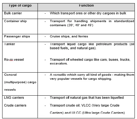
[image:2.595.321.532.80.196.2]In mercantile law, the term cargo applied to a vessel that transports goods, materials and merchandise conveyed in a ship to be transported from one port to another. Technically, the term designates to carry goods only but somehow, it applied in such a sense as to include passengers. Cargo ships are characterized under different categories based on their capacity partly by size, dimension and weight [7]. According to [8], this cargo ships are segregates into the specification namely liners or tramp ships. The liners are ships that travel on routes at fixed scheduled intervals between specified ports while. The ships that travel only when offered to bring the cargo to any port at a fixed contractual price called tramp ships. According to shipping and freight resource, there are few different kinds of cargo ships namely as;
Table. 1 Types of cargo
The Ship Hull
The hull structure design is considered as a very important part in shipyard management. It also known as foundation of the ship, because it is designed to withstands extremely harsh weather conditions due to high durability and resistance [9]. But the hull of ships structure is push down if it is loaded with cargo. According to [10], the large point loads may occur in the structure if the ships structure, equipment, and cargo are distributed unevenly. It also can cause bending forces on the hull if they are distributed differently than the distribution of buoyancy from displaced water.
The hull also need to bear stresses from;
The water pressure from surrounding presses on hull
The ship weight (consists of cargo, component and \hull) heading right toward the hull.
The waves run onto the hull while wind blows against it. Transverse Framing System
On large ship, currently use the transverse framing system and the longitudinal framing system. The transverse framing system provides for continuous transverse frames with the widely spaced longitudinal intercostal between them [11]. Transverse frames are attached to the keel and extend from the keel outward around the turn of the bilge and up to the
[image:2.595.58.279.289.480.2]edge of the main deck. They are closely spaced along the length of the ship, and they define the form of the ship [11].
Fig. 1 Transverse framing member Longitudinal Framing System
Longitudinal framing and is characterized by a plurality of longitudinal girders 7 running parallel to the longitudinal axis of the vessel. These girders are spaced along the sides and bottom of the vessel. Again, the longitudinal bulkheads 9 are mounted from the floor of the vessel vertically throughout a major portion of the hull. A plurality of longitudinal stiffeners or stringers 11 is mounted along the sides of the hull and along the longitudinal bulkheads. These stringers are also preferably in the horizontal plane and run parallel to the longitudinal axis of the vessel. To add additional transverse rigidity to the vessel, a number of transverse webs 13 are mounted within the hull at selected spaced locations.
The increasing size of cargo and the naval vessel through the 20th century, therefore, led to the general acceptance of combined longitudinal deep frame scantlings. A cross-section of typical longitudinal stiffening system is shown in Figure 2. The longitudinal are relatively small and closely spaced, the spacing is regular and the number of stiffeners is rationalized to meet local and global load requirements. Deep longitudinal girders are located at widely spaced intervals across the panel. The transverse web frames and floors run orthogonally to the longitudinal and are usually deeper but more widely spaced [12].
Fig. 2 Example conventional longitudinal framed (left) and advanced double hull (right) midship section
[image:2.595.333.535.549.663.2]International Journal of Innovative Technology and Exploring Engineering (IJITEE) ISSN: 2278-3075, Volume-8 Issue-12, October 2019
Longitudinal Framing vs Transverse Framing System Table. 2 Difference between longitudinal framing and
transverse framing
Transverse Framing Longitudinal Framing There is no influence to
the ship’s resistance to longitudinal bending.
Longitudinal framing system is more resistant to buckling when subjected to compressive stresses while bending in the seaway. Not optimum from the
standpoint of structural efficiency. Transverse framing required strength for the least weight.
Longitudinal is higher structural efficiency. This is because most of the plating stiffeners are in in the aft and fore direction.
DNVGL Rules for Classification and Construction It is a must when designing a ship structure to follow the regulations that have been standardized by the classification society or AICS. In this research, the rules that been used is Germanischer Lloyd which is also known as GL rules.
These rules help us to determine the thickness of designing the model to be analyzed in the research. Every detail and the thickness of every part of the vessel can be determined.
The classification society also provides the arrangement guideline of the containers on the deck of the cargo ship. Based on the rules [13] it stated that if containers are stowed with linear seating in several layers, the total weight of the containers above the first layer shall not exceed the following values:
0.8G for 40ft containers and
1.0G for 20ft containers where G is the container’s maximum gross weight
III. METHODOLOGY
Gathering Data
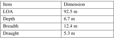
[image:3.595.317.533.68.274.2]Through web sources, the general arrangement for cargo ship is obtained. In this project, only one hull section that being used for simulation. Therefore, only that hull section has being studied from the general arrangement of the cargo ship. Hence, all the data such as its dimensions, type of structures and number of structures consists by the section from the ship that need to be collected before developing the model had been well analyzed as shown in Table 3 and Table 4.
Table. 3 Details for the cargo ship
Item Dimension
LOA 92.5 m
Depth 6.7 m
Breadth 12.4 m
Draught 5.3 m
Table. 4 Details for Hull Structure in the model
Hull Part No. of Parts
Hull 1
Deck Plate 1
Margin Plate 1
Bulkhead 2
Table. 5 Details for Transverse framing Transverse Part No. of Parts Transverse Frame 17
Deck Beam 17
Table. 6 Details for Longitudinal framing Longitudinal Part No. of Parts
Longitudinal Frame
17 at bottom deck 10 on each side shell 17 at bottom hull Developing The Model
The calculation to find the thickness of each plate in transverse framing system model is according to Germanischer Lloyd Classification.
Hull Section
The dimension of hull section; Length of section = 13460 mm Thickness = 113 mm
Width of section = 12400 mm Height of section = 6700 mm Radius of the curve = 1500 mm
[image:3.595.331.522.478.600.2]The thickness of each plate in transverse and longitudinal framing system is calculated according to Germanischer Lloyd Classification.
Table. 7 Thickness for each part in transverse frame
Part Thickness (mm)
Deck Plate 7.74 Margin Plate 8.16 Keel Plate 8.16
Bulkhead 7.00
Transverse Frame 8.00 Deck beam 8.00
Table. 8 Thickness for each part in longitudinal frame
Part Thickness (mm)
Deck Plate 7.74 Margin Plate 8.16 Keel Plate 8.16 Bulkhead 7.00 Longitudinal frame Height (200mm) Width (150 mm)
[image:3.595.51.286.650.730.2]Fig. 3 Assemble model for Transverse Frame
Fig. 4 Assemble model for Longitudinal Frame Container Arrangement on the Model
[image:4.595.310.542.63.431.2]Based on the DNVGL rules it has been stated that the cargo ship with this particular length can hold up to three tier of container on the deck [14]. Therefore, the simulation tested from one tier to three tiers of container and their load distribution. The deformation and the maximum stress will be analyzed. Figure 12 and 13 showed the arrangement of container in the cargo hold.
[image:4.595.55.283.484.605.2]Fig. 5 Container arrangment in finite element software
Fig. 6 Actual container arrangment for three tieractual in finite element software
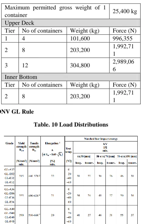
Table. 9 Load Distributions Maximum permitted gross weight of 1
container 25,400 kg
Upper Deck
Tier No of containers Weight (kg) Force (N)
1 4 101,600 996,355
2 8 203,200 1,992,71
1
3 12 304,800 2,989,06
6 Inner Bottom
Tier No of containers Weight (kg) Force (N)
2 8 203,200 1,992,71
1 DNV GL Rule
Table. 10 Load Distributions
In this project, the steel use is grade GL-A36. So, the yield strength must not less than 355 N/mm² and the tensile strength not exceed 630 N/mm². The maximum elongation based on this rule is 21mm.
Convergence Study
The next step in simulation preparation is to determine the most suitable meshing size for the analysis. This is to get the most accurate to the actual result in real situation. The meshing is the process of dividing the whole model to into number of elements so that it will analyzed more accurately by computing all the part of the model perfectly. By doing this, it will give more realistic result.
[image:4.595.47.289.640.710.2]International Journal of Innovative Technology and Exploring Engineering (IJITEE) ISSN: 2278-3075, Volume-8 Issue-12, October 2019
Fig. 7 Convergence Study Graph
The element size is varied from 0.2, 0.25, 0.3, 0.35 and 0.4. The lower the element size, the total element for meshing will be increased. From the graph, it showed that the graph is constant after the total element increased to 15000. The element size for this total element was 0.3. Therefore it can be said that 0.3 element size is the most suitable element size for this project’s simulation. The factor is 0.3 was the starting point for the graph to be saturated and no significant changes on the graph. Therefore, it is the most suitable and more realistic to be run in the analysis.
[image:5.595.316.546.80.184.2]IV. RESULT AND DISCUSSION Transverse Frame
Fig. 8 Total Deformation for Overall model
[image:5.595.326.526.299.414.2]Fig. 9 Total Deformation for Individual Frame
Table. 11 Maximum Deformation & Equivalent Stress of the model (Transverse)
Deformation (mm) & Part
Equivalent stress (MPa) & Part
1 tier
5.954, Bulkhead 104.7, Bulkhead
2 tier
9.282, Bulkhead 145.05, Deck Beam 3
tier
15.204, Bulkhead 213.92, Deck Beam
Based on the Table 11 above, showed the result of simulation for each different value of load so that it was easier to compare with the actual value for the stress stated by DNVGL rules. The result obtained from the analysis showed that none of the maximum deformation of the part neither the equivalent stress bear by the model reach the value from the rules.
[image:5.595.48.288.442.570.2]Longitudinal Frame
Fig. 10 Total Deformation for Overall model
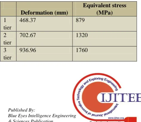
Fig. 11 Total Deformation for Individual Frame Table. 12 Maximum Deformation & Equivalent Stress of
the model at Longitudinal Beam
Deformation (mm)
Equivalent stress (MPa) 1
tier
468.37 879
2 tier
702.67 1320
3 tier
[image:5.595.311.540.450.564.2] [image:5.595.48.281.606.730.2] [image:5.595.309.546.626.831.2]From the Table 12, the longitudinal beam experienced the deformation and maximum stress. Both of the components are the longitudinal frame which the maximum stress at the deck longitudinal frame. The result obtained from the analysis showed that all the deformation and equivalent stress is exceed the DNVGL rules. Based on DNVGL rules, the maximum high tensile strength for steel and maximum deformation are 630MPa and 21mm respectively.
V. CONCLUSION AND RECOMMENDATION
It can be conclude that, for transverse framing system all the result are acceptable based on the DNVGL rules and the transverse framing system surely can hold the load from the container. However, for longitudinal framing system the result obtained from this analysis concludes that this model required more support other than just longitudinal framing system. This is because the stress obtained already exceed the tensile strength from the rules and achieve failure. The thickness of the structural components also can give a great impact to increase the strength of the structure.
Longitudinal strength of ships is a critical factor which affects both the design and operation of the ship. Careful planning and supporting calculations during the design stage should be carried out to ascertain the vessel’s suitability from the strength point of view.
There are some recommendation to increase or improve the capability and strength of the structures of hull section. This will help the cargo ship to be more sufficient during operations and also increase the lifespan of the cargo ship by reducing any major damages towards the structures.
Therefore, it is recommended to use the thicker material especially on the hull section or add more supportive structures due to increase the capability of the hull structure to withstand the loads hence will reduce the total deformation and also stress.
Last but not least, choosing the right type of materials for the structures based on the ship’s operations purposed also influenced the strength of the ship. This is because different materials consist of different yield and tensile strength. ACKNOWLEDGMENT
The author wish to express the appreciation to all team members the effort to complete all the modeling and simulations. Besides, the author also would like to thank to Universiti Kuala Lumpur because had provide facilities to conduct the modeling.
REFERENCES
1. G. O. Young, ―Synthetic structure of industrial plastics (Book style with paper title and editor),‖ in Plastics, 2nd ed. vol. 3, J. Peters, Ed. New York: McGraw-Hill, 1964, pp. 15–64.
2. W.-K. Chen, Linear Networks and Systems (Book style). Belmont, CA: Wadsworth, 1993, pp. 123–135.
3. H. Poor, An Introduction to Signal Detection and Estimation. New York: Springer-Verlag, 1985, ch. 4.
4. B. Smith, ―An approach to graphs of linear forms (Unpublished work style),‖ unpublished.
5. E. H. Miller, ―A note on reflector arrays (Periodical style—Accepted for publication),‖ IEEE Trans. Antennas Propagat., to be published.
6. J. Wang, ―Fundamentals of erbium-doped fiber amplifiers arrays (Periodical style—Submitted for publication),‖ IEEE J. Quantum Electron., submitted for publication.
7. C. J. Kaufman, Rocky Mountain Research Lab., Boulder, CO, private communication, May 1995.
8. Y. Yorozu, M. Hirano, K. Oka, and Y. Tagawa, ―Electron spectroscopy studies on magneto-optical media and plastic substrate interfaces(Translation Journals style),‖ IEEE Transl. J. Magn.Jpn., vol. 2, Aug. 1987, pp. 740–741 [Dig. 9th Annu. Conf. Magnetics Japan, 1982, p. 301].
9. M. Young, The Technical Writers Handbook. Mill Valley, CA: University Science, 1989.
10. (Basic Book/Monograph Online Sources) J. K. Author. (year, month, day). Title (edition) [Type of medium]. Volume(issue). Available: http://www.(URL)
11. J. Jones. (1991, May 10). Networks (2nd ed.) [Online]. Available: http://www.atm.com
12. (Journal Online Sources style) K. Author. (year, month). Title. Journal [Type of medium]. Volume(issue), paging if given. Available: http://www.(URL)
AUTHORSPROFILE
Zainul Azhar Bin Zakaria graduated with B.Eng (Hons) in Mechanical Engineering from Universiti Teknologi PETRONAS (UTP), Malaysia in 2004. He obtained his Master Science (M.Sc.) in Numerical Methods for Engineering from Universidad Politecnica de Catalunya (UPC), Spain in 2013. After graduation in 2004, he worked as Graduate Engineer at Continental Sime Tyres Sdn Bhd at Petaling Jaya. A year after that, he joined Carsem (M) Sdn Bhd at Ipoh as R&D Engineer for 5 years. In Carsem, he was involved in various projects mainly related to thermal simulation projects. Then, he moved to UAC Berhad, Tasek and served about one year as an R&D Engineer before leaving to Spain. In UAC Berhad, he had successfully made the prototype machine for new production line.
Upon his returned to Malaysia, he started to work as a lecturer at Universiti Kuala-Lumpur, Malaysian Institute of Marine Engineering Technology (UniKL MIMET) in July 2016. Until now he had supervised more than 30 final year projects and had published 8 journals as a main and co-author.
Khairul Nisak Md Hasan received B.Eng degree in Electrical and Electronic Engineering in 2004 from Universiti Teknologi Petronas (UTP) and Master degree in Electrical Power Engineering in 2006 from University of New South Wales (UNSW), Australia. She is a lecturer in Universiti Teknologi Petronas (UTP). Her current research work includes power quality in renewable energy, smart grid, and renewable energy harvesting. K.N Md Hasan is a member of The Institute of Electrical & Electronics Engineers (IEEE) and a treasurer for IEEE Women in Engineering Malaysia Chapter.
Nagur Aziz Bin Kamal Bashah (PEng., CEng., Dr.), PhD in Mechanical & Materials Engineering. Publications: Implementation of Reliability-Centred Maintenance (RCM) Strategy in Palm Mill Company for Oil
Extraction Rate (OER) Enhancement., Application of Reliability Centred Maintenance to Optimize Operation and Maintenance in Palm Mill Plant., Application of Risk Based Inspection to Optimize Operation and Maintenance in Oil & Gas Industry., Multi-regression Modeling for Springback Effect on Automotive Body in White Stamped Parts., Accurate Prediction of Springback in Forming of BIW Parts., A Shop Floor Approach for Springback Prediction., Shop-Floor Approach for Springback Prediction of the Automotive Body in White (BIW) Stamped Part., Mathematical Modelling for Springback Prediction in Forming of Stamped Part, Industrial & Research Work: Asset Performance Management (APM) and Sustainable development-related Oil & Gas Energy industry., Asset Lifecycle & Life Extension Management System
International Journal of Innovative Technology and Exploring Engineering (IJITEE) ISSN: 2278-3075, Volume-8 Issue-12, October 2019
HSE performance, operational excellent and business growth.
Muhammad Firdaus Bin Khoirunnizam graduated with BET (Hons) in Naval Architecture & Shipbuilding from Universiti Kuala Lumpur Malaysian Institute of Marine Engineering Technology (UniKL MIMET) in October 2018. Currently working with his own company.
Mohamad Nasri Bin Johari graduated with BET (Hons) in Naval Architecture & Shipbuilding from Universiti Kuala Lumpur Malaysian Institute of Marine Engineering Technology (UniKL MIMET) in December 2018. After graduation, he moved to Kuala Lumpur to pursue his career in Acnetic Naval Consultancy until present.
Amirul Hakim Bin Arifuzzaman graduated with BET (Hons) in Naval Architecture & Shipbuilding from Universiti Kuala Lumpur Malaysian Institute of Marine Engineering Technology (UniKL MIMET) in October 2018. After graduation, he moved to Kuala Lumpur to pursue his career in Marine and Oil & Gas Service Provider industry by joining Argo Engineering as Technical Executive starting November 2018.