1 In-line single-mode fiber variable optical attenuator based on electrically addressable microdroplets
A. Duduś, R. Blue, M. Zagnoni, G Stewart and D. Uttamchandani1 Centre for Microsystems and Photonics, Department of Electronic and
Electrical Engineering, University of Strathclyde, Royal College Building, 204 George Street, Glasgow, G1 1XW, UK.
We report an in-line, fiber optic, broadband variable optical attenuator employing a side-polished, single-mode optical fiber integrated on a digital microfluidics platform. The system is designed to electrically translate a liquid droplet along the polished surface of an optical fiber using electrowetting forces. This fiber optic device has the advantage of no moving mechanical parts and lends itself to miniaturization. A maximum attenuation of 25 dB has been obtained in the wavelength range between 1520 nm and 1560 nm.
Single-mode fiber variable optical attenuators (VOAs) are widely used in fiber optical communications, sensing and signal processing for optical power management1. Progress towards miniaturisation of VOAs has been facilitated by micro-electro-mechanical system (MEMS) implementations of fiber VOAs, such as moving fibers2,3, shutters4,5,6 and mirror types7,8,9, but these devices can have reliability issues associated with the movable micromechanical parts10. An alternative approach for miniature VOAs, which uses no mechanical moving parts, is based on optofluidics technology. Optofluidics, which combines photonics with microfluidics technology, has been applied in recent years to yield a wide range of miniaturised systems which, through fluid manipulation, provide optical functionalities with applications in optical sensing and optical imaging11,12 as well as optical communications13.
To date there have been relatively few optofluidics based VOAs for use in fiber optic applications. One reported example is a tunable microfluidic device consisting of an electrowetting-on-dielectric (EWOD) pump combined with a continuous length of optical fiber into which a long period grating (LPG) was first written14. This device functioned as a narrowband VOA, with an optical dynamic range of approximately 20 dB at the LPG resonant wavelength peak of 1538 nm, and a full width half maximum (FWHM) of 10 nm. However, the aqueous phase employed was a solution of sodium dichromate, which is known to be toxic. Subsequently, it was shown that by specifically engineering the modal group in a few-moded fiber, the LPG phase matching conditions can be extended over a larger bandwidth. Using this approach an optofluidic device demonstrating an attenuation of 20 dB over more than 40 nm bandwidth15 was demonstrated. Researchers have also employed magnetic fields to move a magnetic liquid plug along the external surface of a standard LPG, which generated narrowband optical attenuation of 6.5 dB16 at a center wavelength of 1587 nm. Reza and Riza17 demonstrated a broadband optofluidic VOA which used an electronically controlled variable focus liquid lens positioned in the free space between two fiber-coupled lenses. This device, commonly described as a “fiber-gap” device, exhibited
1 Email: [email protected]
2
variable attenuation with an optical dynamic range up to 40 dB. However, such a device requires the use of special graded index (GRIN) lensed optical fibers to reduce the optical loss in the fiber-gap. Other optofluidic VOA examples have included stretching a liquid crystal across an aperture between lensed fibers18 to achieve broadband attenuation of approximately 30 dB, and a variable interfacial reflection between lensed fibers19 achieving optical attenuation up to 35 dB. Alternatively, temperature has been used to modulate a magnetic fluid within a photonic crystal fiber, demonstrating a thermo-optical tunable attenuator with a broadband profile, but with a limited optical dynamic range of approximately 4 dB20.
Here, we report the development of a broadband optofluidic VOA using a continuous length (i.e. no fiber-gap), side-polished standard single-mode optical fiber based on EWOD techniques21. Compared with other techniques for VOAs, this approach combines the advantages of high dynamic range (0 to >20dB attenuation), broadband operation, low insertion loss (since it is a continuous fiber device), no moving mechanical parts and is amenable to miniaturisation. Furthermore, the implemented EWOD-based actuation of glycerine droplets avoids the use of toxic fluids.
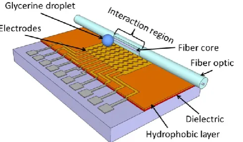
The VOA’s operation is based on the electrically-induced movement of aqueous droplets along a fiber. A droplet (2µL) is placed in contact with the side-polished region of a single-mode optical fiber aligned with a series of microelectrodes. Typically, a potential difference of 180V is applied only between the two electrodes across which the liquid droplet is present to actuate its motion. By creating an electric field gradient between two adjacent electrodes in a multi-electrode linear array, the droplet experiences an electric force that, by overcoming the drop surface tension forces, causes the droplet to move towards the region of high electric field (i.e. electrowetting force). In this way the EWOD22 platform generates a “digital” step-wise movement of the liquid droplet (no voltage is applied for a stationary droplet). In order for the droplet to interact with the guided mode, side-polishing is used to conveniently access the evanescent field of the single-mode fiber 23. The tunneling of the evanescent field of the optical guided mode of the side-polished fiber into the liquid droplet, and the consequent radiative loss of power from the fiber, increases as the droplet approaches the fiber core while it is digitally moved along the polished region by EWOD actuation. The fluid used in our work is a solution of glycerine in water whose refractive index closely matches that of the optical fiber core.
In order to reliably translate a droplet along the electrode array, it is desirable that the droplet shape remains spherical in static conditions and the electrowetting force does not induce droplet break-up. These conditions are obtained when the Weber number, which expresses the ratio between inertial and surface tension forces, is less than 1.1 and the electrowetting number, which expresses the ratio between the electric and surface tension forces, is greater than 124.The Weber number is defined as , where ρ is the density, v is the velocity of motion, l is the drop contact radius and γ is the surface tension between the liquid and gas phases. The electrowetting number is defined as , where c is the capacitance per unit area of the dielectric layer (F/m2) and V is the applied potential. In our system, the droplet translation condition is satisfied as We~0.3 and η~2. This indicates that the electrowetting force allows droplet translation in a digital format without inducing break-up during its motion.
3
thickness of the cladding along the polished region. Thus, variable attenuation of the optical power carried by the fiber core can be achieved as the droplet moves along the fiber.
After polishing, the fiber was aligned and attached to the EWOD platform (Fig.1). The side-polished fiber was positioned with the polished surface standing perpendicular to the electrodes plane. The EWOD platform consisted of photolithographically patterned aluminium microelectrodes passivated with a dielectric (1.5 μm of AZ-4562 photoresist) and, on top of this, a hydrophobic layer (100 nm of Teflon AF2400). The width of each electrode was 600 µm with a 70 µm inter-electrode spacing. The length of the electrode array was 20 mm, allowing a droplet to traverse along the entire polished region of the fiber. The refractive indices of the fiber core and the droplet (glycerine-water solution) were 1.4600 and 1.4602, respectively. The refractive index of the glycerine solution was measured using an Atago Master-RI refractometer. The volume of the droplet, manually dispensed, was 2 µl and the contact length of the droplet upon the fiber was estimated to be 1.26 mm. The fiber surface was coated with a thin hydrophobic layer (Aquapel Glass Treatment, PPG Industries Inc., USA) to prevent glycerine residue being left on the fiber surface.
Fig. 1. Schematic of the EWOD platform (not to scale).
[image:3.595.179.425.294.438.2]An electrical potential difference was sequentially applied to adjacent electrode pairs along the array causing the droplet to move digitally along the polished region of the fiber. A square waveform of 10 V amplitude at a frequency of 1 kHz was supplied by a waveform generator (Agilent 3228A) and was subsequently amplified (A400, FLC Electronics) to 180 V. Broadband ASE light from an erbium doped fiber amplifier (EDFA) was used to inject optical power into the polished fiber and the power output from the fiber was monitored by a photoreceiver (LNP-2, Optosci Ltd, UK). A PicoScope (Pico Technology Ltd, UK) data logger recorded the photoreceiver output voltage in real time as the droplet moved step-wise along the polished region of the fiber.
Fig. 2 shows the experimental comparison of the change in optical transmission through two different side-polished fiber VOAs when droplets of different refractive indices are moved along the polished region. One polished fiber (fiber 1) was acquired from Phoenix Photonics Ltd (UK) while the second polished fiber (fiber 2) was produced in-house using the fiber polishing process mentioned above25. The main difference between the two fibers is the polishing depth and surface quality. The in-house fiber had a deeper polishing depth (less remaining cladding) but a poorer surface finish quality. Good surface quality is important for low insertion loss while polishing depth determines the maximum attenuation that can be achieved.
4
highest attenuation achieved with fiber 1 was 22 dB and was 25 dB for fiber 2 demonstrating the effect of remaining cladding thickness on achievable attenuation. The wavelength dependent loss (WDL) of the side-polished fiber VOA at different values of attenuation was obtained on an optical spectrum analyzer (Agilent 86140B) and is shown in Fig. 3. The WDL was measured over the optical band from 1520 nm to 1560 nm. At the highest attenuation the WDL reaches 1.1 dB for a droplet refractive index of 1.4602
[image:4.595.174.414.167.356.2]Fig. 2. Optical transmission through side-polished fibers with respect to droplet position. Using droplet refractive index of 1.4602 achieves maximum attenuation of 22 dB (fiber 1) and 25 dB (1550 nm) (fiber 2), while using droplet refractive index of 1.4606 achieves maximum attenuation of 12 dB (1550 nm) (fiber 1).
Fig. 3. Broadband optical performance of the VOA showing the wavelength dependent loss for various attenuations corresponding to fiber 1 (Fig. 2) with refractive index 1.4602.
[image:4.595.178.418.441.629.2]5
, (1)
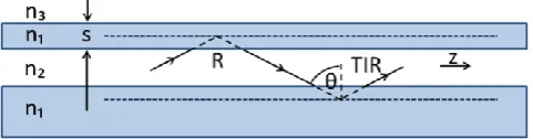
[image:5.595.185.426.156.219.2]where R is reflectivity, η is the number of reflections at the upper boundary per unit length, and z is the propagation direction.
Fig. 4. Schematic of the ray optics approach applied to a side-polished optical fiber.
The reflectivity for frustrated total internal reflection can be calculated from27:
, (2)
where s is the remaining cladding thickness and φ21 and φ13 are the phase shifts for the
reflection coefficients at the n2/n1 boundary and the n1/n3 boundary respectively, given by27:
(3)
, (4)
where √ , √ , √ , n1, n2, n3 are the refractive
indices of the fiber cladding, fiber core, and the external medium respectively, ne is the
effective index of the guided mode and . The reflection coefficient thus depends on the refractive index of the core, cladding and surrounding medium and, critically, on the remaining cladding thickness, s. Over the wavelength range of interest (tested over 1520 - 1560 nm), the effect of wavelength on the attenuation is theoretically small since k0 changes
6
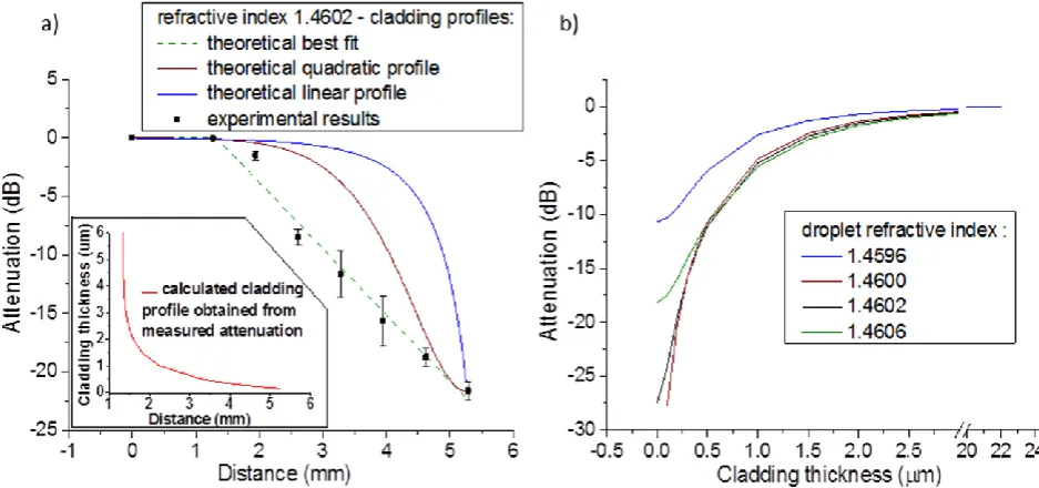
an increase in the contact length from 1.2 mm to 2.0 mm, an attenuation of over 45 dB is achievable.
Fig. 5. (a) Theoretical and experimental results of the optical attenuation for various cladding profile through a polished SMF as a function of droplet position (b) theoretical attenuation as a function of the cladding thickness using a discrete droplet of different refractive indices (1.2 mm contact length) applied to the polished region for a wavelength of 1550nm.
In summary, we have theoretically and experimentally demonstrated the concept of an in-line broadband optical fiber VOA controlled by optofluidic actuation. A side-polished single mode fiber was integrated onto an EWOD platform and created a VOA with an attenuation range up to 25 dB. The attenuation range is limited to around 28 dB according to the theoretical analysis for a droplet contact size of 1.2 mm. However, in many situations this range is adequate for the particular application. Current and future work is focused on improving this system by reducing the overall size of the platform and reducing the actuation voltage whilst automating the droplet actuation with a computer controlled interface. Furthermore, stability of operation and repeatability will also be improved either by engineering an environmentally sealed, humidity-controlled optofluidic device with in-built droplet generation or by creating a thin oil layer over the droplet to prevent evaporation28.
References
1C. Lee and J. A. Yeh, J. Micro/Nanolith. MEMS MOEMS 7, 021003-1 (2008). 2A. Unamuno and D. Uttamchandani, IEEE Photonic Tech. Lett. 18, 88 (2006).
3X. Dai, X. Zhao, G. Ding, and B. Cai, J. Microlith. Microfab. Microsyst. 4, 041304-1
(2005).
4J. Zawadzka, L. Li and D. Uttamchandani, IET Sci. Meas. Technol. 151, 61 (2004). 5J. C. Chiou and W. T. Lin, Opt. Commun. 237, 341 (2004).
6R. R. A. Syms, H. Zou, J. Stagg, and H. Veladi, J. Micromech. Microeng. 14, 1700 (2004). 7H. Cai, X. M. Zhang, C. Lu, A. Q. Liu, and E. H. Khoo, IEEE Photonic Tech. Lett. 17, 402
(2005).
8C. Lee, Microsyst. Technol. 13, 41 (2007).
[image:6.595.78.547.116.336.2]7 10O.Tabata, T. Tsuchiya, O. Brand, G. K. Fedder, C. Hierold J. G. Korvink (eds), Reliability
of MEMS: Testing of Materials and Devices (Wiley-VCH., Weinheim, 2008).
11Y. Yang, A. Q. Liu, L. K. Chin, X. M. Zhang, D. P. Tsai, C. L. Lin, C. Lu, G. P. Wang and
N. I. Zheludev, Nat. Commun. 3, 651 (2012).
12Xin Heng, David Erickson, L. Ryan Baugh, Zahid Yaqoob, Paul W. Sternberg, Demetri
Psaltis and Changhuei Yang, Lab Chip 6, 1274 (2006).
13Aram J. Chung and David Erickson, Opt. Express 19 8602 (2011).
14J. Hsieh, P. Mach, F. Cattaneo, S. Yang, T. Krupenkine, K. Baldwin and J. A. Rogers, IEEE
Photonic Tech. Lett. 15, 81 (2003).
15B. R. Acharya, T. Krupenkine, S. Ramachandran, Z. Wang, C. C. Huang and J. A. Rogers,
Appl. Phys. Lett. 83 4912 (2003).
16M. Konstantaki, A. Candiani, and S. Pissadakis, J. Eur. Opt. Soc.-Rapid 6, 11007 (2011). 17S. A. Reza and N. A. Riza, Opt. Commun. 282, 1298 (2009).
18S. Xu, H. Ren, J. Sun, and S. Wu, Opt. Express 20, 17059 (2012).
19M. I. Lapsley, S. S. Lin, X. Mao, and T. J. Huang, Appl. Phys. Lett. 95, 083507 (2009). 20Yinping Miao, Bo Liu, Kailiang Zhang, Yan Liu, and Hao Zhang, Appl. Phys. Lett. 98,
021103 (2011).
21F. Mugele and J. C. Baret, J. Phys.: Condens. Matter. 17 R705 (2005). 22W. C. Nelson and Chang-Jin Kim, J. Adhes. Sci. Technol. 26 1747 (2012). 23C. D. Hussey and J. D. Minelly, Electron. Lett. 24, 805 (1998).
24J. Berthier, Microdrops and digital microfluidics, (William Andrew Publishing, Norwich,
NY, 2008).
25Z. Chen, and C. Bai, J. Electron. Sci. Technol. China 6, 445 (2008). 26 G Stewart and B Culshaw, Opt. and Quant. Electron., 26, 249 (1994).
27M Born and E Wolf, Principles of optics: electromagnetic theory of propagation,
interference and diffraction of light, Chapter 1 (Cambridge University Press, 7th edition, NY 1999).
28S. K. Küster,* M. Pabst,* R. Zenobi and P. S. Dittrich,17th International Conference on