Al-Hanafy, Waleed and Weiss, S. (2009) A new low-cost discrete bit loading using greedy power allocation. In: The Third Mosharaka International Conference on Communications, Computers and Applications (MIC-CCA2009) 26-28 October, Amman, Jordan, October 2009.
http://strathprints.strath.ac.uk/27152/
Strathprints is designed to allow users to access the research output of the University of Strathclyde. Copyright © and Moral Rights for the papers on this site are retained by the individual authors and/or other copyright owners. You may not engage in further
distribution of the material for any profitmaking activities or any commercial gain. You may freely distribute both the url (http://strathprints.strath.ac.uk) and the content of this paper for research or study, educational, or not-for-profit purposes without prior
permission or charge. You may freely distribute the url (http://strathprints.strath.ac.uk) of the Strathprints website.
A New Low-Cost Discrete Bit Loading using Greedy Power Allocation
Waleed Al-Hanafy?‡ and Stephan Weiss?
? Centre for Excellence in Signal & Image Processing, Dept. of EEE, Univ. of Strathclyde, Glasgow, Scotland, UK
‡ Electronics & Comm. Eng. Dept., Faculty of Electronic Engineering, Menoufia Univ., Menouf, Egypt
Email:{waleed.alhanafy, stephan.weiss}@eee.strath.ac.uk
Abstract—In this paper we consider a low cost
bit loading based on the greedy power allocation (GPA). Compared to the standard GPA, which is optimal in terms of maximising the data through-put, three suboptimal schemes are suggested, which perform GPA on subsets of subchannels only. We demonstrate how these schemes can reduce complexity. Two of the proposed algorithms can achieve near optimal performance by inclu-ding a transfer of residual power between subsets at the expense of a very small extra cost. By simulations, we show that the two near optimal schemes perform best in two separate and distinct SNR regions.
Index Terms—Adaptive loading, discrete
bit-loading, power allocation, water-filling algorithms, constrained optimisation, greedy algorithms.
I. INTRODUCTION
In OFDM, multiplexing over MIMO channels, or general transmultiplexing techniques a num-ber of independent subcarrier or subchannel arise for transmission, which differ in SNR. Maxi-mising the channel capacity or data throughput under the constraint of limited transmit power leads to the well-known and simple waterfilling algorithm [1]. Waterfilling is generally followed by bit loading, wherebi bits are allocated to the
QAM symbols transmitted over theith
subchan-nel. To achieve an identical target bit error ratio
(BER) across all subchannels leads to bi ∈ R,
which needs to be rounded off to the nearest integer b(r)i = bbic, thus lowering the overall
throughput. Furthermore, unbounded modulation orders b(r)i → ∞ in the case of infinite SNR are required to efficiently utilise the transmit power but are practically unfeasible.
In order to optimise capacity and throughput, a wide range of methods has been suggested in the
literature. Pure waterfilling-based solutions have been reported in [2], [3], [4], leading to some of the above stated problems. Reallocation of the excess power when realising the target BER givenb(r)i ∈Zand the SNR in theith subchannel has lead to a rate-optimal algorithm known as the greedy algorithm [5], [6], of which a number of difference variation have emerged constraining the average BER [7] or the total power [8]. For a good review of greedy algorithms, please refer to [9].
While achieving rate optimality, the family of greedy algorithms is also known to be greedy in terms of computing requirements. There-fore, reduced complexity schemes are either waterfilling-based only [2] or aim at simplifi-cations [10]. In this paper we propose a no-vel suboptimal greedy algorithm, whereby the power re-allocation is performed in subsets of the subchannels. We show that some simple overall redistribution can be included at very low cost, whereby two different methods on terms of approximate overall optimisation are discussed. We show that these suboptimal schemes, while greatly reducing complexity, hardly sacrifice any performance compared to the full greedy al-gorithm, provided that the correct algorithmic version is applied for specific SNR regions.
II. GREEDYAPPROACH REVIEW
A. Problem Statement
We consider the problem of maximising the
transmission rate over anNR×NT narrowband
MIMO system, whereby the channel is
charac-terised by a matrix H ∈ CNR×NT of complex
coefficients which describe the complex gains
between pairs of the NT transmit and the NR
receive antennas. The singular value decompo-sition (SVD) can be used to decouple the
sys-tem H into N = rank{H} ≤ min{NT, NR}
subchannels whose gains are represented by the singular valuesσi, i= 1. . . N and are ordered
such that σi ≥ σi+1. The ith subchannel
expe-riencing the gain σi will be used to transmit bi
bits per symbol. We here consider maximising the sum rate
max
N
X
i=1
bi, (1)
with total power budget and target bit error ratio (BER) constraints. This set of constraints can be formulated as
N
X
i=1
Pi≤Pbudget,Pb,i=Pbtargetandbi ≤bmax,∀i
(2)
where Pi is the amount of power allocated to
the ith subchannel to achieve a BER Pb,i, and
bmax is the maximum number of permissible
allocated bits per subchannel. Note that BERs
are assumed equal, i.e. Pb,i = Pbtarget in (2)
for all subchannels i = 1· · ·N and therefore
the subscript i will be dropped from the BER
notation.
In order to further elaborate on the constraints,
the channel-to-noise ratio of the ith subchannel
can be defined as
CNRi =
σi2
N0
, (3)
whereN0 is the total noise power at the receiver. The signal-to-noise ratio of this subchannel is
γi=Pi×CNRi. (4)
BER can be related to the symbol error rate
(SER) Ps as
Pb≈Ps/log2Mk, (5)
where
Ps= 1−
1−2
1−√1
Mk
Q
r
3γi
Mk−1
2
(6) is the SER for a square QAM modulation of
order Mk for a subchannel SNR γi [11]. The
ith subchannel can carry symbols of bk-bits,
bk = log2Mk with the minimum required SNR
obtained from (6) and (5) as
γkQAM= Mk−1 3
"
Q−1 1− √
1− Pblog2Mk
2 1−1/√Mk
!#2 ,
(7)
where Q−1 is the inverse of the well-known Q
function (the tail probability of the normalised Gaussian distribution)
Q(x) = √1
2π
∞
Z
x
e−u2/2du . (8)
The problem is solved in two steps, (i) a uni-form power allocation (UPA) initialisation step and (ii) the Greedy algorithm, both described below.
B. UPA Algorithm and Initialisation Setup
The initial step of uniform power allocation is performed by the following steps:
1) Calculate γkQAM for all Mk,1 ≤ k ≤ K
and Pb =Pbtarget using (7), where MK is
the maximum QAM constellation that is potentially permissible by the transmission system, i.e.,MK = 2b
max .
2) Equally allocate Pbudget among all
sub-channels1≤i≤N:
γi=Pi×CNRi=
Pbudget
N ×CNRi. (9)
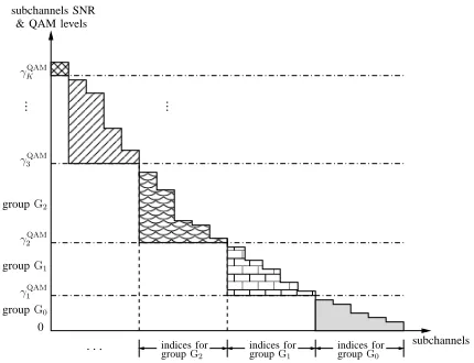
3) Reside subchannels according to their SNR
γi into QAM groups Gk,0 ≤ k ≤ K
bounded by QAM levelsγkQAMandγkQAM+1
with γ0QAM = 0 and γKQAM+1 = +∞ (cf.
Fig. 1 and Fig. 2) such as:
γi≥γkQAMandγi < γkQAM+1 . (10)
4) For each group Gk, load subchannels
Mk and compute the group’s total
alloca-ted bits
Bku= X
i∈Gk
bui,k = X
i∈Gk
log2Mk (11)
withBu
0 = 0, and the total excess (unused)
power
Pkex = P
i∈Gk
(γi−γQAMk )
CNRi
= P
i∈GkPi−
γQAM
k
CNRi .
(12)
5) The overall system allocated bits and used power for the uniform power allocation scheme are therefore,
Bu= K
X
k=1
Bku (13a)
Puused=Pbudget−Pex, (13b)
where Pex is the overall excess (unused)
power of the UPA scheme given by,
Pex =
K
X
k=0
Pkex. (14)
Note that the summation in (13a) starts
from group G1 since none of the
sub-channels in G0 will be loaded in this
initialisation.
...
0 subchannels SNR
& QAM levels
γQAM3
γQAMK
γQAM1
subchannels
γQAM2
groupG1
groupG2
...
indices forG0
[image:4.612.325.540.71.236.2]groupG0
Figure 1: Grouping subchannels of multicar-rier systems into QAM groups according to their SNRs in (9) and step (3) Sec. II-B
...
0 subchannels SNR
& QAM levels
γ3QAM
indices for indices for
γ2QAM
γKQAM
subchannels indices for
groupG0 groupG1
groupG2
γ1QAM groupG1 groupG2
...
· · · groupG0
Figure 2: Grouping ordered subchannels of MIMO systems into QAM groups according to their SNRs in (9) and step (3) in Sec. II-B
The difference between the power budget and
the overall power Puused allocated by the UPA
scheme can be improved by a number of algo-rithms, this represents a useful measure to indi-cate how well a bit loading scheme utilises the
total system transmit power Pbudget. The closer
thePused
u is toPbudget, the better is the utilisation of power achieved by a specific power loading scheme. Therefore, it is clear from (13b) that the
amount of excess power Pex
k that is left unused
has an obvious impact on the performance of the uniform power allocation scheme. The worst
cases are Pex
0 and PKex which reveal inefficient
power allocations in situations of low-to-medium and medium-to-high SNRs, respectively, as will be discussed in Sec. IV.
C. Greedy Power Allocation (GPA) Algorithm
Based on the initialisation step described in the previous section, the full GPA algorithm [5], [6], [9] performs an iterative re-distribution of the unallocated power of the UPA algorithm given in (14) applying the algorithmic steps de-tailed in Table I. At each iteration, this algorithm tries to increase bit loading by upgrading the subchannel of the least power requirements to the next higher QAM level through an exhaustive search, step (5) in Table I. When either of the following events occurred: i) the remaining po-wer cannot afford any further upgrades or ii) all
[image:4.612.75.281.477.660.2]the algorithm stops resulting in an overall system allocated bits and used power given, respectively, by
Bgpa= N
X
i=1
bgpai (15a)
[image:5.612.75.281.244.469.2]Pgpaused=Pbudget−Pdgpa. (15b)
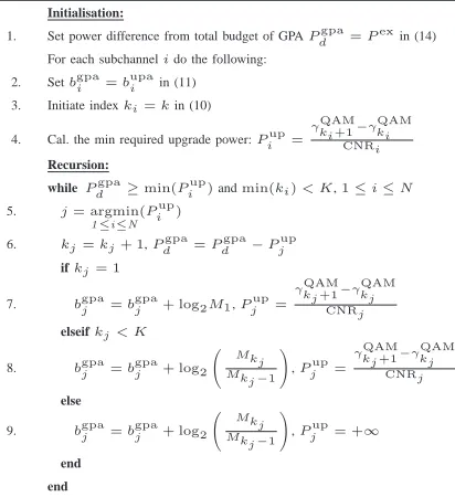
Table I: Full GPA algorithm applied to the initialisation step of the UPA algorithm
Initialisation:
1. Set power difference from total budget of GPAPdgpa=Pexin (14) For each subchannelido the following:
2. Setbgpai =bupai in (11) 3. Initiate indexki=kin (10)
4. Cal. the min required upgrade power:Piup=
γQAM ki+1−γ
QAM
ki
CNRi
Recursion:
whilePdgpa≥min(Piup)andmin(ki)< K,1≤i≤N
5. j= argmin
1≤i≤N
(Piup)
6. kj=kj+ 1,Pdgpa=P
gpa
d −P
up
j ifkj= 1
7. bgpaj =bgpaj + log2M1,Pjup= γQAM
kj+1−γ QAM
kj
CNRj elseifkj< K
8. bgpaj =bgpaj + log2
Mkj Mkj−1
!
,Pjup=
γQAM kj+1−γ
QAM
kj
CNRj
else
9. bgpaj =bgpaj + log2 MkMkj
j−1
!
,Pjup= +∞
end end
III. PROPOSED LOW-COST GPA
With Buk as defined in (11) and Pkex in (12), three low-cost greedy algorithms are proposed to efficiently utilise the total excess power of the
uniform power allocation Pex =PK
k=0Pkex and
hencePbudget. More precisely, GPA is separately
accomplished for each QAM group Gk aiming
to increase the total bit allocation to this group and therefore the overall system allocated bits.
Based on the way of making use of Pkex, we
propose three different algorithms, which below are referred to as (i) QAM-Level Greedy Power Allocation (QAM-L-GPA), (ii) Power Moving-up Greedy Power Allocation (Mu-GPA) and (iii) Power Moving-down Greedy Power Allocation (Md-GPA).
A. QAM-L-GPA Algorithm
As discussed in Sec. II, optimum discrete bit loading with total power and maximum QAM level constraints can be performed by the greedy power allocation (GPA) approach. However, the direct application of GPA is computationally very costly due to the fact that at each simulation iteration an exhaustive sorting of all subchannels is required as evident from Table I.
1) Model Description: A simplification of
GPA can be achieved if subchannels are firstly
divided into QAM groupsGk,0≤k≤K
accor-ding to their SNRs as shown in Fig. 1, where we assume a multicarrier systems with subchannel not ordered with respect to their SNR yet. After ordering or due to implicit ordering of the singu-lar values in case of SVD-based decoupling of MIMO systems, the grouping as shown in Fig. 2 arises. GPA is therefore independently applied
to each group Gk, trying to allocate as much
of the excess power Pkex that is remaining after application of the UPA algorithm within a QAM group. This excess power is iteratively allocated to subchannels within this group according to the greedy concept with the aim to upgrade as many subchannels as possible to the next QAM level.
Table II: QAM-L-GPA algorithm for sub-channels in the kth QAM group Gk
In:bui,k,Pkex,γQAMd,k =γkQAM+1 −γkQAM,CNRiOut:Bgk,P
LO
k
1. ∀i∈Gk, cal. the min required upgrade power:Piup= γd,kQAM
CNRi 2. Initiatebgi,k=bi,ku andPkLO=Pkex
whilePkLO≥min(Piup) 3. j= argmin
i∈Gk
(Piup)
4. PkLO=PkLO−Pjup ifk= 0
5. bgj,k= log2M1,Pjup= +∞
else
6. bgj,k=bgj,k+ log2MkMk+1,Pjup= +∞
end end
7. Bgk= P
i∈Gk
bgi,k
The pseudo code for the above allocation
within the kth QAM group Gk of the
QAM-L-GPA algorithm is given in Table II. Note that different from the standard GPA, this algorithm permits upgrades to the next QAM level only
[image:5.612.331.534.470.629.2]steps (5) and (6) in Table II) and therefore may
leave some left-over (LO) power PkLO for each
QAM group Gk, resulting in a total left-over
power of
PgLO=
K−1
X
k=0
PkLO+PKex. (16)
Intuitively, for the overall performance of the QAM-L-GPA algorithm, the algorithm in
Table II has to be executed K times, once for
each QAM group, from G0 to GK−1 resulting
in an overall system that allocates bits and uses power according to
Bg = K−1
X
k=0
Bkg+BKu (17a)
and
Pgused=Pbudget−PgLO. (17b)
2) Complexity Assessment: The QAM-L-GPA algorithm can be viewed as a QAM-L-GPA applied to individual QAM groups. Instead of jointly applying GPA algorithm across all subchannels which consequently requires high system com-plexity especially for large numbers of subchan-nels, the GPA algorithm only addresses a subset of subchannels within a specific QAM group at a time. Beyond the division of the QAM grouping concept, a further reduction in complexity can be achieved if subchannels are ordered in their gains
CNRi, as the case of SVD-based decoupling of
subchannels for MIMO systems. In this case the search step (3) in Table II can be replaced by a simple incremental indexing.
Referring to Table I and Table II the com-putational complexity of both GPA and QAM-L-GPA algorithms is summarised in Table III, whereby the no. of operations is assessed for each algorithm. Both subchannels “no order” and “order” cases are considered. Note that for the GPA algorithm ordering subchannels does not lead to any improvement in complexity as the search step (5) in the while loop has to include all subchannels. This is due to the fact that by relaxing the grouping concept it is pos-sible to find subchannels in lower QAM levels that need less power to upgrade than others in
higher QAM levels. The quantities L1, L2 in
Table III denote the no. of iterations of the
while loops for GPA (Table I) and QAM-L-GPA
(Table II), respectively. Note that it is expected
that L1 ≥L2 as the Pex in (14) collected from
all subchannels has to be re-distributed by the GPA algorithm, whilePkexin (12) collected from
only subchannels i ∈ Gk is considered by the
QAM-L-GPA algorithm. For the QAM-L-GPA
algorithm α and β stand, respectively, for the
no. of QAM groups occupied by all subchannels
N and the no. of subchannels per QAM group.
Obviously, α and β are not easily quantified as
they both depend onCNRiwhich is aχ2random
variable, therefore the complexity of QAM-L-GPA is assessed in a heuristic fashion. In the worst case and by assuming that subchannels are uniformly distributed across all QAM groups the complexity of QAM-L-GPA is approximately given by the second line formula (cf. Table III) which is still less than its GPA counterpart.
Table III: Computational analysis for both GPA and QAM-L-GPA algorithms
algorithm no. of operations GPA (no order) L1(2N+ 7) + 4N+ 1
GPA (order) same as (no order) QAM-L-GPA (no order) α[L2(2β+ 4) + 2β+ 2]≈
K
L2(2KN+ 4) +
2N K + 2
QAM-L-GPA (order) α[L2(β+ 5) + 2β+ 2]≈ K
L2(NK+ 5) +
2N K + 2
B. Mu-GPA Algorithm
The QAM-L-GPA algorithm results in unused
PkLO for each QAM group. This residual power
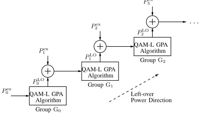
can be exploited by a second stage, whereby it is proposed to move power upwards starting from the lowest QAM group, as outlined in Fig. 3 and by the flowchart in Fig. 4. This modifies the QAM-L-GPA algorithm by considering the
left-over powerP0LOof the QAM groupG0after
run-ning the QAM-L-GPA algorithm on that group , and assign this power for redistribution to group
G1. Any left-over power after running
QAM-L-GPA onG1is then passed further upwards toG2, and so forth. At thekth algorithmic iteration, the
Mu-GPA algorithm is working withGkand tries
Pex 0
Algorithm QAM-L GPA
Algorithm QAM-L GPA
Algorithm QAM-L GPA
· · ·
GroupG0
PLO
0 GroupG1
Pex
1
PLO
1
Pex
2
PLO
2
GroupG2
Pex
3
[image:7.612.346.510.72.427.2]Left-over Power Direction
Figure 3: Mu-GPA algorithm arrangements with final left-over power in (18)
left-over power of the application of the
QAM-L-GPA algorithm to the previous group Gk−1,
i.e., Pkex +PkLO−1 (cf. Fig. 3). Finally, the
left-over power resulting from the QAM groupGK−1
is added to the excess power of the Kth QAM
groupPKex to end up with a final left-over power
PMuLO−g=PKLO−1+PKex (18)
of this algorithm. The overall system allocated bits and used power for this algorithm are, res-pectively,
BMu−g = K−1
X
k=0
BkMu−g+BuK (19a)
PMuused−g =Pbudget−PMuLO−g (19b)
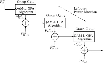
C. Md-GPA Algorithm
A second algorithm is proposed to exploit the
residual power PkLO of each QAM group but in
a reverse direction compared to the Mu-GPA al-gorithm, starting from the highest-indexed QAM
groupGK−1downwards to the least-index QAM
groupG0. This procedures is illustrated in Fig. 5 which show the direction of the left-over power
flow. Proceeding downwards, at the kth stage
this algorithm applies the QAM-L-GPA algo-rithm for the available power, comprising of the excess power missed by the UPA algorithm of
the previous QAM group (Gk+1 in this case)
as well as the left-over power of the previous stage, i.e., Pkex+1 +PkLO+1, as also characterised in Fig. 5. Therefore, the excess power of the QAM group under consideration is not utilised
Compute final left-over power and overall
Gk,0≤k≤K
For all QAM groups:
setbMu−g
i,k =b
u i,k
Apply QAM-L GPA algorithm for
Setk= 1
Apply QAM-L GPA algorithm for subchannnels in groupGkwith
Updatek=k+ 1
subchannnels in groupG0with
P0exto obtain:P0LOand
BMu0 −g=P
i∈G0bMui,0−g
BMu−g
k =
P
i∈Gkb
Mu−g i,k PkLO−1+Pkexto obtain:PkLOand
Yes
End
No Isk=K
allocated bits using (16) and (17a), respectively
Figure 4: Flowchart of the Mu-GPA algorithm
within this group but is transferred to the next working group along with the left-over power of the former QAM group. This will finally results in a left-over power of
PMdLO−g =P0LO+P0ex. (20)
The flowchart of this algorithm is analogous to the Mu-GPA algorithm. The overall system allocated bits and used power are, respectively,
BMd−g = K−1
X
k=0
BkMd−g+BuK (21a)
PMdused−g =Pbudget−PMdLO−g. (21b)
IV. SIMULATIONRESULTS AND
DISCUSSION
[image:7.612.71.268.74.184.2]Pex K
Algorithm QAM-L GPA
Algorithm QAM-L GPA Power Direction Left-over Algorithm
QAM-L GPA GroupGK−1
GroupGK−2
Pex
K−1
· · ·
GroupGK−3
Pex
K−3
Pex
K−2
PLO
K−3
PLO
K−2
PLO
[image:8.612.73.268.73.186.2]K−1
Figure 5: Md-GPA algorithm arrangements with final left-over power in (20)
similarly in utilising the power PLO
k for all
groups k,0 ≤ k ≤ K − 1 that remained
unused by the QAM-L-GPA algorithm. The two algorithms differ in the direction in which left-over power is transferred. Below we compare the two algorithms with the UPA, GPA, and the QAM-L-GPA approaches.
Simulations are conducted over 104 instances
of a 10x10 MIMO system, where the entries
of the MIMO channel H are drawn from a
complex Gaussian distribution with zero-mean
and unit-variance, i.e., hij ∈ CN(0,1).
Re-sults presented below refer to ensemble averages
across the 104 channel realisations for target
BERPbtarget = 10−3 and various levels of SNRs
using square QAM modulation schemes Mk =
4k, k= 1· · ·K withK= 4 being the maximum
permissible QAM level of constellation size, i.e.,
MK = 256 which is equivalent to encoding 8
bits per data symbol.
The total system throughput is examined and shown in Fig. 6 for all proposed algorithms in ad-dition to both UPA and standard GPA algorithms. It is evident that UPA represents an inefficient way of bit loading since the performance is ap-proximately 5 to 10 dB below other algorithms, and provide approximately half the throughput at 10 dB SNR.
Of the proposed low-cost greedy algorithms, both Mu-GPA and Md-GPA algorithms outper-form the QAM-L-GPA without the refinement stage to allocate residual power across QAM groups. Interestingly, Mu-GPA performs better at low SNR, while Md-GPA performs better at hi-gher SNRs. This can be attributed to the fact that
for low-to-medium SNRs PKex (which is missed
0 10 20 30 40 50 60 0
10 20 30 40 50 60 70 80
Throughput [bits/symbol]
SNR [dB] 14 15
23 24 25 26 27
29 30 31 32 60
65 70
B
u
B
gpa
B
g
B
Mu−g
B
[image:8.612.336.541.83.250.2]Md−g
Figure 6: Overall throughput for a 10x10 MIMO system with Pbtarget=10−
3
by the Mu-GPA) in this case will be relatively low and can be allocated without violating the
constraint on maximum QAM levels. WhileP0ex
(which is missed by the Mg-GPA) is most likely to be high — please see (12) and Fig. 2 — such that the remaining power in the lowest QAM group is insufficient to lift subchannels across the QPSK boundary. For medium-to-high SNRs PKex > P0ex can be expected to be high, and then Md-GPA is likely to be advantageous in its bit allocation, as the maximum QAM level constraint is beginning to be felt.
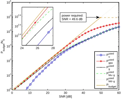
The data throughput performance of the va-rious algorithms can also be confirmed when considering the power utilisation. Fig. 7 shows the total power available for allocation, and the levels of power allocation that is reached by the different algorithms. For Md-GPA and Mu-GPA, it can be noted that within their respective superiority regions, both are very close to the performance of the standard GPA which de-monstrate the good utilisation of the left-over power missed by the QAM-L-GPA algorithm. For high SNR, both QAM-L-GPA and Mu-GPA algorithms behaves like the UPA algorithm due to the increase of Pex
K which is missed by both
of them and therefore deteriorates their perfor-mances.
Finally, for very high SNRs most subchannels
their SNRs, γi in (9), exceed the highest QAM
levelγKQAMin (7). As a result, the overall system throughput of all different algorithms reaches its expected maximum.
0 10 20 30 40 50 60 100
101 102 103 104 105 106
Pbudget
/N
0
SNR [dB]
Pused
u
Pused gpa
Pused
g
Pused
Mu−g
Pused
Md−g
P
budget
24 26 28 102.4
102.5
[image:9.612.82.288.152.321.2]102.6 power required: SNR = 49.6 dB
Figure 7: Transmit power used to achieve
Pbtarget=10− 3
with a min transmit power required by (7) of approximately 49.6 dB
V. CONCLUSIONS
Power allocation to achieve maximum data throughput under constraints on the transmit power and the maximum QAM level has been discussed. The optimum solution is provided by the Greedy Algorithm, which operates across all subchannels but is computationally very ex-pensive. Therefore, in this paper sub-optimal low-cost alternatives have been explored. The common theme amongst the proposed algorithms is to restrict the Greedy Algorithm to subsets of subchannels, which are grouped according to the QAM level assigned to them in the uniform power allocation stage. In order to exploit excess (unused) power in each subset, two algorithms were created which carry left-over power for-ward into the next subset that is optimised by a local greedy algorithms. Two different schemes have been suggested, of which one moves the left-over power upwards from the lowest to the highest subgroup, where in the high SNR case a limitation by the maximum defined QAM level can restrict the performance. A second scheme moves the power from the highest towards the
lower subgroups, whereby at low SNR the chan-nel quality in the lowest subgroups may not be such that it can be lifted across the lowest QAM level, and hence no bits may be loaded with the excess power. However, in general both algorithms perform very close to the GPA in their respective domains of preferred operation, thus permitting to allocate power close to the performance of the GPA at a much reduced cost.
REFERENCES
[1] D. Palomar and J. Fonollosa, “Practical Algorithms for a Family of Waterfilling Solutions,” IEEE
Tran-sactions on Signal Processing, vol. 53, no. 2, pp. 686–
695, Feb 2005.
[2] B. Krongold, K. Ramchandran, and D. Jones, “Com-putationally efficient optimal power allocation algo-rithms for multicarrier communication systems,” IEEE
Transactions on Communications, vol. 48, no. 1, pp.
23–27, Jan 2000.
[3] E. Baccarelli, A. Fasano, and M. Biagi, “Novel Efficient Bit-Loading Algorithms for Peak-Energy-Limited ADSL-Type Multicarrier Systems,” IEEE
Transactions on Signal Processing, vol. 50, no. 5, pp.
1237–1247, May 2002.
[4] X. Zhang and B. Ottersten, “Power Allocation and Bit Loading for Spatial Multiplexing in MIMO Sys-tems,” in IEEE International Conference on Acoustics,
Speech, and Signal Processing, (ICASSP ’03), vol. 5,
April 2003, pp. V–53–56.
[5] J. Campello, “Optimal Discrete Bit Loading for Mul-ticarrier Modulation Systems,” in IEEE International
Symposium on Information Theory, Aug 1998, p. 193.
[6] ——, “Practical bit loading for DMT,” in
Commu-nications, 1999. ICC ’99. 1999 IEEE International Conference on, vol. 2, 1999, pp. 801–805 vol.2.
[7] A. M. Wyglinski, F. Labeau, and P. Kabal, “Bit Loading with BER-Constraint for Multicarrier Sys-tems,” IEEE Transactions on Wireless
Communica-tions, vol. 4, no. 4, pp. 1383–1387, July 2005.
[8] L. Zeng, S. McGrath, and E. Cano, “Rate Maximiza-tion for Multiband OFDM Ultra Wideband Systems Using Adaptive Power and Bit Loading Algorithm,” in IEEE Fifth Advanced International Conference
Telecommunications, AICT ’09, Venice/Mestre, Italy,
May 2009, pp. 369–374.
[9] N. Papandreou and T. Antonakopoulos, “Bit and Po-wer Allocation in Constrained Multicarrier Systems: The Single-User Case,” EURASIP Journal on
Ad-vances in Signal Processing, vol. 2008, pp. 1–14,
2008.
[10] C. Assimakopoulos and F.-N. Pavlidou, “New bit loading algorithms for DMT systems based on the greedy approach,” Wireless Communications and
Mo-bile Computing, vol. 6, no. 8, pp. 1047–1056, 2006.