City, University of London Institutional Repository
Citation:
Behbahani, Peyman (2010). Connection Robustness for Wireless MovingNetworks Using Transport Layer Multi-homing. (Unpublished Doctoral thesis, City University London)
This is the unspecified version of the paper.
This version of the publication may differ from the final published
version.
Permanent repository link:
http://openaccess.city.ac.uk/1089/Link to published version:
Copyright and reuse: City Research Online aims to make research
outputs of City, University of London available to a wider audience.
Copyright and Moral Rights remain with the author(s) and/or copyright
holders. URLs from City Research Online may be freely distributed and
linked to.
City Research Online: http://openaccess.city.ac.uk/ [email protected]
Connection Robustness for Wireless Moving Networks Using Transport Layer Multi-homing
By:
Peyman Behbahani
Under Supervision of Dr Veselin Rakocevic
A THESIS SUBMITTED TO THE SCHOOL OF ENGINEERING AND MATHEMATICAL SCIENCES, CITY UNIVERSITY, LONDON IN PARTIAL FULFILMENT OF THE
REQUIREMENTS FOR THE DEGREE OF
Doctor of Philosophy
Abstract
Given any form of mobility management through wireless communication, one useful enhancement is improving the reliability and robustness of transport-layer connections in a heterogeneous mobile environment. This is particularly true in the case of mobile networks with multiple vertical handovers. In this thesis, issues and challenges in mobility management for mobile terminals in such a scenario are addressed, and a number of techniques to facilitate and improve efficiency and the QoS for such a handover are proposed and investigated. These are initially considered in an end-to-end context and all protocols and changes happened in the middleware of the connection where the network is involved with handover issues and end user transparency is satisfied.
Acknowledgements
First, I would like to thank my supervisor, Dr Veselin Rakocevic. I could not have produced this work without the constant impetus to succeed, support and guidance given by him.
Next, I would like to thank my sponsoring company, T-Systems and particularly BIT (Broadband wireless Internet access in public Transport) project manager, Prof. J. Habermann, who not only funded my research but provided interesting insights and opportunities for interaction with industrial representatives, I am most grateful for this.
Also, thanks to Professor Panos Liatsis my second supervisor and member of Mobile Network Research Group specially Dr Muttukrishnan Rajarajan, Ehsan Hamadani and Soroush Jahromizadeh that I couldn’t have achieved this without them. Particular thanks must be given to Professor Abdol-Hamid Aghvami director of Centre for Telecommunications Research (CTR) and its members specially Mohammad Ghavami, Oliver Holland, Nima Nafisi, Reza Dilmaghani, Vasilis Friderikos, Reza Nakhai and Mona Ghassemian that have partaken in some very useful discussions and finally Dominic Stiles for his valuable editorial remarks.
List of Acronyms and Abbreviations
Acronym/Abbreviation Description
2G 2nd Generation
3G 3rd Generation
3GPP 3rd Generation Partnership Project
AAA Authentication, Authorization and Accounting
ACK ACKnowledgement
AMPS American Mobile Phone Systems
AP Access Point
AR Access Router
ASCONF Address Configuration Change Chunk
ATM Asynchronous Transfer Mode
b Binary Digits (Bits)
B Bytes
BIT Broadband wireless Internet access in public Transport
BR Bridge Router
BU Binding Update
BWA Broadband Wireless Access
CDMA-2000 Code Division Multiple Access Ver. 2000
CN Correspondent Node
CN Core Network
cwnd Congestion Window
CoA Care of Address
CS Circuit Switched
CSCF Call State Control Function
DAR Dynamic Address Reconfiguration
DHCP Dynamic Host Configuration Protocol
DSL Digital Subscribe Line
DVB Digital Video Broadcasting
DVB-AR Digital Video Broadcasting Access Router DVB-H Digital Video Broadcasting - Handheld
FA Foreign Agent
FDD Frequency Division Duplex
FEC Forward Error Correction
FTP File Transport Protocol
GGSN Gateway GPRS Support Node
GPRS General Packet Radio Service
GSM Global Systems for Mobile Communication
H/O Entity Handover Entity
Acronym/Abbreviation Description
HIP Host Identity Payload
HIT Handover Initiation Time
HMIPv6 Hierarchical Mobile IP version 6
HSS Home Subscriber Server
I-CSCF Interrogating Call State Control Function
IETF Internet Engineering Task Force
IP Internet Protocol
ISP Internet Service Provicer
LAN Local Area Network
LFN Local Fixed Node
LLC Logical Link Control
LMN Local Mobile Node
MAC Media Access Control
MAN Metropolitan Area Network
MAP Mobility Anchor Points
MCoA Multiple Care of Addresses
ME Mobile Equipment
MH Mobile Host
MIP Mobile IP
MIPv4 Mobile IP version 4
MIPv6 Mobile IP version 6
MN Mobile Node
MPEG Motion Pictures Experts Group
MPEG-TS MPEG Transport Stream
MR Mobile Router
MR-HA Mobile Router-Home Agent
MSC Mobile Switching Centre
mSCTP Mobile Stream Control Transmission Protocol
MTU Maximum Transmission Unit
Node B Node B (UMTS Basestation)
NAD Network Access Device
NAI Network Access Identifier
NAT Network Address Translation/Translator
NEMO Network Mobility
NMT Nordic Mobile Telephone Systems
NS-2 Network Simulator Version 2
nSCTP NEMO Stream Control Transmission Protocol
ORC Optimised Route Cache Management Protocol
OSI Open Systems Interconnection Basic Reference Model
PAN Personal Area Network
Acronym/Abbreviation Description
PPP Packet Pair Probing
PS Packet Switched
QoS Quality of Service
QPSK Quadrature Phase Shift Keying
RAS Remote Access Service
RFC Request For Comments
RNC Radio Network Controller
RNS Radio Network Subsystem
RO Route Optimization
RRM Radio Resource Management
RWP Random WayPoint
SACK Selective ACK
S-CSCF Serving Call State Control Function SCTP Stream Control Transmission Protocol
SCTP/IP Stream Control Transmission Protocol / Internet Protocol
SGSN Serving GPRS Support Node
SIP Session Initiation Protocol
SLS Service Level Subscription
SSN Stream Sequence Number
TCP Transmission Control Protocol
TCP/IP Transmission Control Protocol/ Internet Protocol
TDD Time Division Duplex
TSN Transmission Sequence Number
UDP User Datagram Protocol
UE User Equipment
UMTS Universal Mobile Telecommunications Service UMTS-AR Universal Mobile Telecommunications Service
Access Router
USIM User Services Identify Module
UTRAN UMTS Terrestrial Radio Access Network
VMN Visiting Mobile Node
VPN Virtual Private Network
W-CDMA Wideband Code Division Multiple Access
Wi-Fi Wireless Fidelity
WiMAX World Interoperability for Microwave Access
WLAN Wireless Local Area Network
WLAN-AR Wireless LAN Access Router
Table of contents
CHAPTER 1. INTRODUCTION ... 15
1.1. CHALLENGES ... 17
1.1.1. Congestion Control ... 17
1.1.2. Effect of Irresponsible Non-congestion Control Protocols ... 18
1.1.3. Provision of Mobility ... 19
1.2. CONTRIBUTIONS OF THIS THESIS ... 20
1.2.1. Soft and seamless vertical handover for moving networks ... 20
1.2.2. Advance fairness and robustness in all IP mobile networks ... 21
1.2.3. QoS provisioning of multi-link / multi-homed communications ... 22
1.3. CONTENT OF THIS THESIS ... 23
1.3.1. Mobility Management Solutions (Chapter 2) ... 23
1.3.2. Multi-homing and group mobility management challenges (Chapter 3) ... 23
1.3.3. nSCTP: Seamless Handover for Moving Networks (Chapter 4) ... 24
1.3.4. Performance analysis for end-to-end parameters in nSCTP and NEMO (Chapter 5) ... 25
1.3.5. Simulation studies of the performance of SCTP and nSCTP (Chapter 6) ... 26
1.3.6. QoS provisioning for SCTP (Chapter 7) ... 26
CHAPTER 2. WIRELESS COMMUNICATION AND MOBILITY MANAGEMENT ... 28
2.1. INTRODUCTION ... 28
2.2. HETEROGENEOUS ENVIRONMENT IN MOBILE COMMUNICATIONS ... 31
2.2.1. UMTS ... 33
2.2.2. WLAN ... 36
2.2.3. Wireless Metropolitan Area Network (WMAN) ... 37
2.3.OSI REFERENCE MODEL AND MOBILITY MANAGEMENT ... 38
2.4. APPLICATION BASED TERMINAL MOBILITY ... 40
2.5. TRANSPORT LAYER BASED MOBILITY ... 41
2.5.1. SCTP ... 42
2.5.2. Mobile SCTP (mSCTP) ... 46
2.6. NETWORK LAYER BASED MOBILITY ... 49
2.7. DATA LINK BASED MOBILITY (IEEE802.21) ... 52
2.8.GROUP MOBILITY MANAGEMENT ... 54
CHAPTER 3. MULTI-HOMING AND GROUP MOBILITY MANAGEMENT SOLUTIONS ... 56
3.1. MULTI-HOMING SOLUTIONS ... 56
3.2.1. Hierarchical Mobile IP (HMIPv6) ... 60
3.2.2. Prefix Scope Binding Updates ... 61
3.2.3. Mobile Router Tunnelling Protocol ... 62
3.2.4. Optimised Route Cache Management Protocol for Network Mobility (ORC) ... 64
3.2.5. Comparison ... 64
3.3.NETWORK MOBILITY (NEMO) ... 66
3.3.1. NEMO Components ... 66
3.3.2. Tunnelling Configuration ... 68
3.4. CHAPTER SUMMARY AND PROBLEM DEFINITION ... 71
CHAPTER 4. NSCTP: SEAMLESS HANDOVER FOR MOVING NETWORK .. 73
4.1. BENEFITS OF MULTI-HOMING IN NEMO ... 74
4.1.1. Permanent and Ubiquitous access ... 74
4.1.2. Load sharing ... 75
4.1.3. Reliability ... 75
4.1.4. Aggregate bandwidth ... 75
4.2. MULTI-HOMING CONFIGURATIONS FOR NEMO ... 76
4.2.1. Possible Configurations ... 76
4.2.2. Important Criteria in Multi-homing Configurations ... 77
4.2.3. Selected Configuration ... 78
4.3. TRANSPORT LAYER TUNNELLING ... 79
4.3.1. IP Encapsulator ... 80
4.3.2. SCTP/IP Encapsulator ... 81
4.3.3. IP Decapsulation ... 83
4.3.4. SCTP/IP Decapsulator ... 83
4.4. NSCTP PROTOCOL ... 85
4.5. DATA AND SIGNALLING PATHS IN NEMO ... 88
4.6. DATA AND SIGNALLING PATHS IN NSCTP ... 90
4.7. ENHANCED MR AND THE MR’S HOME NETWORK ... 93
4.8. CHAPTER SUMMARY ... 94
CHAPTER 5. PERFORMANCE ANALYSIS OF TCP OVER NSCTP ... 95
5.1.TRANSPORT LAYER TUNNELLING OVERVIEW ... 96
5.1.1. Advantages of transport layer tunnelling ... 96
5.1.2. Drawbacks of transport layer tunnelling ... 97
5.2. HANDOVER DELAY INVESTIGATION IN NSCTP AND NEMO ... 98
5.2.1. Handover Delay in NEMO ... 98
5.2.2. Handover Delay in nSCTP ... 98
5.3. END-TO-END THROUGHPUT INVESTIGATION IN NSCTP AND NEMO ... 99
5.4. PACKET LOSS INVESTIGATION IN NSCTP AND NEMO ... 103
5.4.1. Packet loss in NEMO (LNEMO) ... 103
5.4.2. Packet loss in nSCTP (LnSCTP) ... 104
5.5. COMPARISON OF ANALYTICAL RESULTS IN NEMO AND NSCTP ... 104
5.5.1. Handover Latency Comparison ... 104
5.5.2. Throughput Comparison ... 105
5.5.3. Packet Losses Comparison ... 106
5.6. TCP MODEL ... 107
5.7. SCTP MODEL ... 107
5.8. NSCTP MODEL ... 108
5.9. NUMERICAL RESULT AND DISCUSSIONS ... 110
5.10. CHAPTER SUMMARY ... 112
CHAPTER 6. SIMULATION STUDIES OF THE PERFORMANCE OF SCTP AND NSCTP ... 114
6.1. NETWORK SIMULATOR 2 ... 116
6.2. VERTICAL HANDOVER WITH THE BASIC SCTP ... 118
6.2.1. Simulation Scenario ... 118
6.2.2. Packet arrivals Comparison ... 120
6.3. VERTICAL HANDOVER WITH MULTI-HOMING FEATURE OF SCTP ... 123
6.3.1. Simulation Scenario ... 124
6.3.2. Error-Free Environment Scenario ... 125
6.3.3. Scenarios with Random Errors ... 131
6.4. LINKS WITH SUDDEN BREAKAGE ... 134
6.5. NSCTP SIMULATION ... 137
6.6. CHAPTER SUMMARY ... 139
CHAPTER 7. QOS PROVISIONING IN SCTP ... 141
7.1. BANDWIDTH ESTIMATION TECHNIQUES AT TRANSPORT LAYER ... 142
7.1.1. Single Packet Technique ... 142
7.1.2. Packet Pair Technique ... 143
7.2.IMPORTANT PARAMETERS ON A POLICY BASED HANDOVER ... 144
7.3. BANDWIDTH ESTIMATION ALGORITHM FOR NSCTP ... 146
7.3.1. Monitoring the packet loss and the consecutive packet loss ... 147
7.3.2. Estimating the Available Bandwidth on the Primary link ... 148
7.3.3. Estimating the Available Bandwidth on the Alternative link(s) ... 149
7.4. SIMULATION STUDIES ON DYNAMIC SWITCHOVER TECHNIQUE WITHIN AN SCTP ASSOCIATION ... 150
7.4.1. Simulation Scenario ... 151
7.5. RESULTS COMPARISON AND DISCUSSION ... 157
7.6. CHAPTER SUMMARY ... 161
CHAPTER 8. CONCLUSION ... 162
8.1. APPLICABILITY OF THE SOLUTIONS PROVIDED ... 164
8.2. POTENTIAL FOR FUTURE WORK ... 164
PUBLICATIONS RESULTING FROM THIS THESIS ... 167
List of figures
FIGURE 2-1:SUMMARY OF THE FUNCTIONALITY OF DIFFERENT GENERATIONS OF MOBILE
NETWORKS ... 33
FIGURE 2-2: UMTS ARCHITECTURE ... 34
FIGURE 2-3: SIP SIGNALLING ... 41
FIGURE 2-4: MULTI-HOMING SCENARIO ... 44
FIGURE 2-5: MULTI-STREAMING SCENARIO ... 45
FIGURE 2-6: SCTP ASSOCIATION WITH BOTH MULTI-STREAMING/MULTI-HOMING FEATURES (END POINT A IS A SENDER AND B IS A RECEIVER) ... 46
FIGURE 2-7:ASCONFCHUNK FORMAT ... 47
FIGURE 2-8:ASCONFPARAMETER FORMAT FOR ADD-IP,DELETE-IP AND SET PRIMARY-IP ... 47
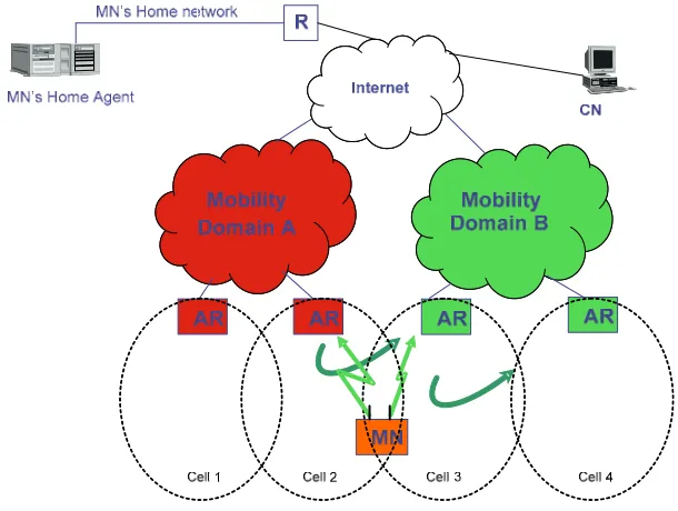
FIGURE 2-9: MICRO AND MACRO MOBILITY IN MULTI-HOMED SCENARIO WITH MSCTP ... 48
FIGURE 2-10: BASIC OPERATION OF MOBILE IP ... 52
FIGURE 2-11: IEEE 802.21 ARCHITECTURE ... 53
FIGURE 2-12: HANDOVER SCENARIOS (A) SINGLE NODE MOBILITY (B) GROUP MOBILITY ... 54
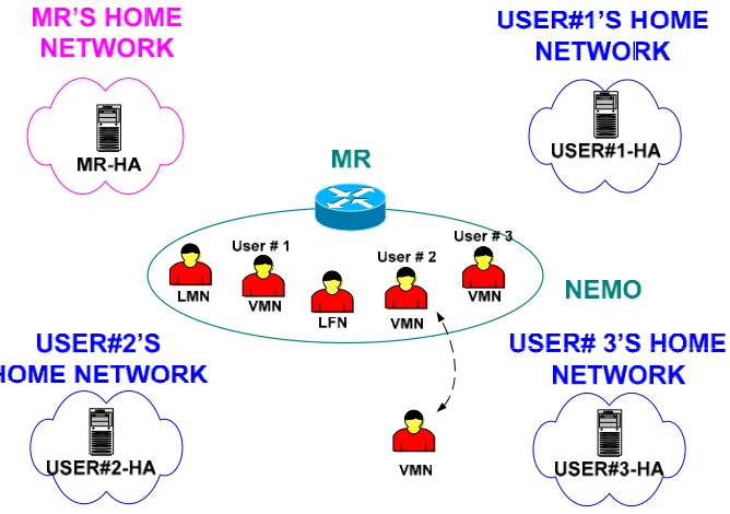
FIGURE 3-1: NEMO COMPONENTS ... 66
FIGURE 3-2 SENDER AND RECEIVER IP ADDRESS FIELDS IN NEMO WHEN CN IS SENDER ... 68
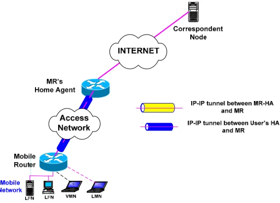
FIGURE 3-3:IP TRAFFIC BETWEEN A VMN AND A CN USING NEMO;1:ORIGINAL DATA PATH,2: INNER TUNNEL,3:OUTER TUNNEL ... 70
FIGURE 3-4: DATA PATH FOR A VMN ... 70
FIGURE 3-5: DATA PATH FOR A LFN/LMN ... 71
FIGURE 4-1: IP-IN-IP ENCAPSULATION ... 81
FIGURE 4-2: SCTP/IP ENCAPSULATION MECHANISMS FOR ONGOING FLOW UNDER NSCTP STRUCTURE ... 82
FIGURE 4-3:SCTP/IPENCAPSULATION AND PROTOCOL STACK IN NSCTP OUTER TUNNEL ... 82
FIGURE 4-4:SCTP/IP DECAPSULATION MECHANISMS FOR ONGOING FLOW IN NSCTP STRUCTURE84 FIGURE 4-5: NSCTP HANDOVER MANAGEMENT BY THE EFFECT OF SIGNAL STRENGTH THRESHOLDS ... 86
FIGURE 4-6: SCTP/IP ENCAPSULATION MECHANISMS FOR ONGOING FLOW UNDER NSCTP STRUCTURE ... 87
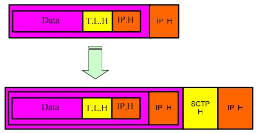
FIGURE 4-7: PACKET FORMAT (A) IN NEMO (B) IN NSCTP ... 88
FIGURE 4-8: DATA AND SIGNALLING PATHS IN NEMO STRUCTURE ... 89
FIGURE 4-9:DATA AND SIGNALLING PATHS IN NSCTP STRUCTURE ... 91
FIGURE 4-10:ENHANCED ENCAPSULATION FOR THE MR AND THE MR’S HA ... 93
FIGURE 5-1: THROUGHPUT COMPARISONS WHILE THE TRANSMISSION RATE CHANGES ... 106
FIGURE 5-2: NSCTP BLOCK DIAGRAM STRUCTURE ... 108
FIGURE 6-1: SIMPLIFIED USER’S VIEW OF NS, TAKEN FROM[71] ... 117
FIGURE 6-2: SIMULATION TOPOLOGY IN A WIRED-CUM-WIRELESS SCENARIO ... 120
FIGURE 6-3: DISTRIBUTION OF BSS IN A 670M*670M AREA ... 120
FIGURE 6-4: COMPARISON OF AGGREGATION RECEIVED DATA IN ZERO DROP AND 5% LOSS RATE SCENARIOS ... 121
FIGURE 6-5:COMPARISON OF AGGREGATION DATA-PACKET ARRIVAL IN DIFFERENT TRANSPORT LAYER PROTOCOL WITH HANDOVERS BASED ON MIP IN AN ERROR-FREE ENVIRONMENT ... 122
FIGURE 6-6: COMPARISON OF AGGREGATION DATA-PACKET ARRIVAL IN DIFFERENT TRANSPORT LAYER PROTOCOL WITH HANDOVERS BASED ON MIP AND 5% UNIFORM PACKET LOSSES .. 122
FIGURE 6-7: END-TO-END MULTI-HOMED SIMULATION TOPOLOGY ... 124
FIGURE 6-8: STRUCTURE OF A MULTI-HOMED SCENARIO IMPLEMENTED IN NS-2 ... 125
FIGURE 6-9: AGGREGATION OF RECEIVED DATA ... 127
FIGURE 6-10: EFFECT OF CONGESTION WINDOW IN MULTI-HOMED SITUATION ... 127
FIGURE 6-11: AGGREGATION OF RECEIVED DATA ... 128
FIGURE 6-12:EFFECT OF CONGESTION WINDOW IN MULTI-HOMED SITUATION ... 128
FIGURE 6-13: AGGREGATION OF RECEIVED DATA ... 129
FIGURE 6-14: EFFECT OF CONGESTION WINDOW IN MULTI-HOMED SITUATION ... 130
FIGURE 6-15: AGGREGATION OF RECEIVED DATA ... 130
FIGURE 6-16: EFFECT OF CONGESTION WINDOW IN MULTI-HOMED SITUATION ... 131
FIGURE 6-17: AGGREGATION OF RECEIVED DATA IN A WLAN-WLAN HANDOVER WITH DIFFERENT ERROR-RATE ON THE LINKS ... 133
FIGURE 6-18:AGGREGATION OF RECEIVED DATA IN A UMTS-UMTS HANDOVER WITH 5% ERROR -RATE ON BOTH LINKS ... 133
FIGURE 6-19: AGGREGATION OF RECEIVED DATA IN A WLAN-UMTS HANDOVER WITH 5% ERROR-RATE ON BOTH LINKS ... 133
FIGURE 6-20: NETWORK TOPOLOGY ... 134
FIGURE 6-21: PACKET-ARRIVAL RATE IN THE SUDDEN LINK-BREAKAGE SCENARIO ... 136
FIGURE 6-22: CONGESTION WINDOW SIZE IN THE SUDDEN LINK-BREAKAGE SCENARIO ... 136
FIGURE 6-23: SIMULATION TOPOLOGY ... 137
FIGURE 6-24:COMPARISON THE RESULTS OF THE NSCTP AND NEMO HANDOVER ... 138
FIGURE 7-1:PACKET PAIR OPERATION ... 143
FIGURE 7-2: SIMULATION SCENARIO FOR NSCTP WHILE MORE THAN ONE CONNECTION IS AVAILABLE ... 147
FIGURE 7-3: HANDOVER IMPROVEMENT FLOWCHART BASED ON CONSECUTIVE AND TOTAL NUMBER OF PACKET LOSS ... 148
FIGURE 7-4: BOTTLENECK LINK THAT CAUSES PACKET QUEUING WHEN TWO CONSCETIVE HEART BIT SEND CLOSE ENOUGH TOGETHER ... 149
FIGURE 7-6: BANDWIDTH RESPONSE ACQUIRED FROM THE AVAILABLE LINK IN THE WIRELESS CLOUD IN FIGURE 7-5 ... 153
FIGURE 7-7: GOODPUT COMPARISON OF TWO SCHEMES - ORIGINAL SCTP AND SCTP WITH
DYNAMIC CHANGEOVER MECHANISM ... 154
FIGURE 7-8: THE PROBLEM OF STARTING AT A LOW BANDWIDTH LINK AND THEN SWITCH TO THE HIGHER BANDWIDTH ... 155
FIGURE 7-9: THE PROBLEM OF SLOW START OF SCTP WHILE A HANDOVER IS PERFORMING ... 156
FIGURE 7-10: GOODPUT COMPARISON IN STATIC AND DYNAMIC HANDOVER SCENARIOS ... 156
FIGURE 7-11: AGGREGATION OF RECEIVED PACKET ON DIFFERENT SWITCHING OVER TECHNIQUES (STATIC, DYNAMIC AND ENHANCED DYNAMIC HANDOVER) ... 157
FIGURE 7-12: PERFORMANCE COMPARISON IN DYNAMIC SWITCHOVER IN AGGRESSIVE,
CONSERVATIVE AND SLUGGISH SCENARIOS ... 159
FIGURE 7-13: THE IMPACT OF THRESHOLD SWITCHOVER ON THE AMOUNT OF TRANSFERRED DATA AND THE NUMBER OF HANDOVERS IN LOW BANDWIDTH SCENARIOS ... 160
List of Tables
TABLE 2-1:A SUMMARISE OF SCTP,TCP AND UDP FUNCTIONALITIES ... 43
TABLE 6-1: SUMMARY OF SIMULATION PARAMETERS ... 125
TABLE 6-2: SUMMARY OF TIMING PARAMETERS ... 126
TABLE 6-3: SUMMARY OF TIMING PARAMETERS ... 132
TABLE 6-4: SIMULATION PARAMETERS ... 135
Chapter 1.
Introduction
As integrated circuit transistor density continues to improve according to Moore’s law and operating voltages and power dissipation are cut, more and more terminal functionalities are being implemented. For example, the integration between mobile modem chipsets and WLAN modules is becoming possible, offering connectivity to WLANs as well as to existing cellular networks and featuring compatibility with 802.11b and 802.11g protocols on both CDMA2000 and WCDMA (UMTS) networks. In a wireless access infrastructural point of view, a wide selection of technologies is available in many places throughout the globe. Often, these technologies are designed to fulfil dissimilar purposes, or to provide substitute levels of QoS to users, perhaps with alternative pricing structures. If users were allowed to use or switch between these technologies, dependent on changes in circumstances such as availability, utilised application, or undertaking the importance of the communication, then overall user satisfaction could be enhanced. And if users were allowed to switch between these technologies based on their mobility, for example to take advantage of a high-bandwidth low-cost service available in a limited area (such as a WLAN hot spot), then perceived service quality would be further improved.
In many situations the mobility of diverse users is matched; for instance, in public transport scenarios a number of users remain in the close proximity during the movement of the transportation vehicle. In Mobile IP (MIP)[1], signalling is required for each of these users upon each change in their topological point of attachment to the Internet. However, if the terminal movements could be dealt with as a group, with all terminals using the same network, the group handover would be much more efficient. In the group mobility scenario, signalling used to handover the network with a single set of messages between network’s gateway and the gateway’s home network. This is the principle behind the concept of NEtwork MObility (NEMO)[2].
problem of link failures by allowing a transport layer session to bind multiple IP addresses at each end point of communication. This feature provides both endpoints with multiple communication paths and thus, gives them the ability to failover (switch) to an alternate path when a link failure occurs or a minimum required QoS has not been met. The simultaneous connectivity can be achieved in a heterogeneous environment by using multiple ISPs or multiple access technologies, such as cellular networks (e.g. GPRS, UMTS) and wireless LANs and MANs (e.g. 802.11, WiMAX).
The current transport layer protocols, TCP and UDP, do not support multi-homing. TCP allows binding to only one network address at each end of connection. This is the main reason why a new transport-layer protocol, the Stream Control Transmission Protocol (SCTP)[3], is being investigated in this thesis. SCTP allows binding of one transport layer association to multiple IP addresses at each end of the association. SCTP has a built-in failure detection and recovery system, known as failover, which allows associations to dynamically send traffic to an alternate peer IP address when needed. SCTP’s failover mechanism is static and does not adapt to application requirements or network conditions.
Furthermore, SCTP provides the multi-streaming functionality. Multi-streaming allows independent delivery among data streams. This means that, the application data can be partitioned into multiple streams. These portions or data chunks are formed inside an SCTP packet and each packet can contain multiple data chunks from different applications. The chunks header contains Transmission Sequence Number (TSN), Stream ID and Stream Sequence Number (SSN) that can provide independent delivery of each stream to the application.
advantage of this type of protocol is a much wider applicability of the solutions; furthermore, this is consistent with expectations for future-generation mobile systems.
1.1.
Challenges
From the transport layer point of view three significant technical challenges in reliable connections are: congestion control, effect of irresponsible non-congestion control protocols, and the provision of mobility. They are discussed here.
1.1.1.Congestion Control
Congestion control mechanism operates in the Internet to moderate the transmission rate to fairly share the bottleneck bandwidth. The approach of Transmission Control Protocol (TCP) as the most common transport protocol in the Internet is “additive increase multiple decrease”. In any end to end connections such as provided by TCP, congestion control only needs to select the appropriate transmission rate based on congestion on the path between the source and the receiver. However, in reliable multi-homed scenarios, there may be multiple network paths for each source-receiver pairing. Hence significant questions arise: Which source-receiver path would be more appropriate for transmission to be selected? How can this selected path be changed in reaction to dynamic variations in congestion, bandwidth or any other changes in the network circumstances among source-receiver paths?
Interference: Cellular telephone channels are subject to adjacent-cell communications using the same signal frequency. The problem with such interference is that it occupies the same frequency band as the desired communication signal, and has a similar structure.
Noise: Noise signals have little structure and arise from both human and natural sources. That can increase the error-rate in the air interface during transmission. Error-rate is typically very low in wired media; approximately 10-12 in fibre-optics and 10-3 in UTP cable, while, in a wireless link it is typically 10-1 or 1 error every 10 bits[4].
Limited Bandwidth: This is the maximum rate at which the transmission
medium can carry data. Based on communication theorem stated by Shannon–Hartley [5], the maximum amount of error-free digital data that can be transmitted over a communications channel (e.g., a copper wire or an optical fibre) with a specified bandwidth in the presence of noise. In fibre optics it is more than 10Gbps, and in UTP it is up to 1Gbps. In a wireless link, the maximum is about 100Mbps, and significantly reduced in a mobile scenario due to channel fading and noise conditions[4].
Mobility: The physical movement of end-hosts between regions covered
by different networks and access-points are not experienced in wired technology. Change of IP address is a natural consequence of a movement that required router adaptation and appropriated routing which has not defined in a wired scenario. This can include frequent changes in IP addresses and other problems such as brief disconnectivity (blackout) and break-up in data transmission during handover.
1.1.2.Effect of Irresponsible Non-congestion Control Protocols
communication links regardless of consideration of the available bandwidth on the paths. They do not reduce their load on the network when subjected to packet drops. This will result in aggressive capacity consumption by unresponsive protocols in competition with the behaved transport protocols such as TCP and SCTP.
Lack of fairness is the main problem of the above issue that TCP flows reduce their transmission rates in response to congestion, and UDP datagrams use the available bandwidth. This problem will be highlighted more particularly in the mobile network that a combination of UDP and TCP flows need to transfer on the line simultaneously and the volume of UDP connections are high.
1.1.3. Provision of Mobility
In mobile communications, links and data flow are involved in two major mobility models known as micro and macro mobility (intra-domain and inter-domain handover respectively). In micro or intra-inter-domain mobility, handovers are within a subnet which means changes on mobile terminals’ IP addresses are not needed. The major problem arises in a situation when a mobile node moves between two subnets, considering that by definition subnets have different network prefixes. In this case, resuming the connection is subject to releasing the old IP address, acquiring a new IP address from the new subnet, registering it with the home location register in the terminal’s home network and finally informing the corresponding node to resume the connection on the new IP address. This procedure will cause termination of current flow and resuming the communication to the new address of mobile node. It also needs to resubmit all the packets that have not been acknowledged, and thus synchronize the packet transmission between the two IP addresses. The situation will deteriorate when there are several ongoing sessions at the same time. In that case, all the corresponding nodes would have to be notified of the new IP address and all of them have to synchronize the transmission.
pertaining to these terminals to be performed for the group as one. This would improve the efficiency, and likely the reliability, of radio resource control.
1.2.
Contributions of this Thesis
Solutions that can be used to address the above cited challenges for moving network which are discussed and presented in this thesis are as follow:
Soft and seamless vertical handover for moving networks
Advance fairness and robustness in all IP mobile networks
QoS provisioning of multi-link / multi-homed communications
Also they are summarised in this section.
1.2.1.Soft and seamless vertical handover for moving networks
Each layer of network protocol stack could be taking a particular role in the next generation of mobile networks in order to create advance mobility management. Different layers can have different responsibilities to develop a soft and seamless handover in intra and inter domain mobility. Suggesting which layer/layers are most suitable for mobility management is a challenging issue that depends on the system requirement, QoS parameters and the ability for changes in the network architecture that have been addressed in this thesis. Consequently, based on the focus of this thesis a suitable protocol for network mobility has been proposed.
By growing the generation of mobile nodes and networks in all IP scenarios the demands for high data rate transmission in high speed vehicle and public transport were increased. Recently the need for developing a new mobility management protocol has become an essential part of the telecoms research communities.
Efficient network mobility handover is essential to meet the QoS parameters. NEMO suffers from tunnelling overheads while it still inherits the well-known MIP issue which is long handover latency and results in high packet losses and severely reduces its end-to-end performance particularly in vertical handovers[2].
In this thesis a new mobility management protocol for a moving network based on Stream Control Transmission Protocol (SCTP) at the transport layer has been proposed. SCTP facilitated with multi-homing that has been used to handle the mobility issues within mobile network and developing nSCTP (NEMO-SCTP). The concept of nSCTP is “make before break”, using more than one separated interfaces. This can be done in the overlap area of cells in a cellular network topology. While still one of the interfaces is communicating with the old domain, a new connection with the new domain will be established. In the later stage in a suitable time transmission will be switched to the new interface and the communication will be resumed.
Detailed structure and signalling for nSCTP is taken into consideration in this thesis and the performance of this newly developed protocol has been tested through analysis and simulation studies.
1.2.2.Advance fairness and robustness in all IP mobile networks
nSCTP uses a tunnelling method at transport layer in the wireless part of the network. This increases the QoS parameters by moderating the irresponsible protocol (e.g. UDP) that is discussed in section 1.1.2. These greedy protocols do not reduce their transmission rate when the communication is subjected to congestion and they will be taken over all or the greater portion of the available bandwidth in competition with the fairness conforming transport protocol (e.g. TCP). This problem has been addressed in nSCTP by introducing a transport layer tunnelling exactly at the bottleneck section of communication which is more vulnerable to congestion or packet loss. Therefore, the fairness of the system will be increased at the presence of nSCTP.
network is commonly due to instability of the wireless media. A local retransmission of lost packet could greatly enhance the performance of the network if the systems overhead do not apply a huge amount of signalling and processing on the communication link. Developing this solution within nSCTP to activate a local retransmission between a mobile router’s home-agent in the wired part of the communication with a mobile router which is used as a gateway of the mobile network is another contribution of this thesis. This solution introduces a new processing delay on the communication path but increases the performance of handling errors on the wireless hope(s) or portion of the system. Analysing the performance of the system and discovering the optimal threshold of lost packet in the wireless and wired part of network have been addressed.
1.2.3.QoS provisioning of multi-link / multi-homed communications
1.3.
Content of this thesis
After providing some overview to this thesis, the precise content is now introduced. The reasoning and justification behind each of the investigated/proposed technologies is discussed on a chapter-by-chapter basis.
1.3.1.Mobility Management Solutions (Chapter 2)
An important aspect of mobile network performance is mobility management. Through creating mobility management protocols, it is possible to handle handover in different layers of the OSI reference model and thus to infer any requirements that might be needed of the network to carry the traffic load adequately while providing an appropriate QoS to end-users.
To answer the question of which layer(s) is(are) more suitable for handling the mobility is challenging in the mobile network, especially in a heterogeneous infrastructure where moving networks or mobile nodes are involved in vertical and horizontal handovers. In addition, the specification of available wireless technologies in a heterogeneous environment and their impact on the mobility issues is another important part of mobility managements that should be addressed.
In this chapter, a hierarchical model of aspects of mobility management is presented and different proposals for mobility managements are considered. Network, transport and application layers mobility management solutions are taken into consideration. Group mobility management solutions which are the main focus of this thesis are presented.
1.3.2.Multi-homing and group mobility management challenges
(Chapter 3)
number of terminals are about to handover to a new cell, if they are considered as a group the member of that group are not involved in handover issues. This would improve the efficiency, and likely the reliability, of mobility management.
For a single mobile node, there are different basic approaches for performing multi-homing that have been considered in detail in chapter 3 and a variety of challenges have been considered. Multi-homing is gaining more interest recently in mobile networks. A mobile network wishes to be multi-homed for the purposes of ubiquitous access, load sharing, reliability and aggregated bandwidth. There are different methods of multi-homing for NEMO that are discussed in this chapter. For the purpose of multi-homing in this thesis a single mobile router, a single home agent and a single mobile node prefix have been considered.
The proliferations of wireless technologies have given rise to the possibility of multiple accesses for a mobile multi-homed host. There are several reasons for multi-homed mobile networks that can refer to the aspects of fault resilience and redundancy, load balancing, service value and policy. There are different approaches to multi-homing in different layers of the OSI reference model. Multi-homing related works have been considered in this chapter and a comparison of benefits and drawbacks of each solution have been considered.
Also, in this chapter the challenges introduced by the use of network mobility, and different related works on group mobility managements are provided. This chapter provides a comparison between the solutions and introduces NEMO basic support protocol [2] which is the platform for the next chapters of this thesis.
1.3.3. nSCTP: Seamless Handover for Moving Networks (Chapter 4)
for a group mobility scenario will provide many limitations like software incompatibility and hardware limitations as a multi-interfaces node in mobile networks are not always achievable.
The scenarios investigated in this chapter contain the new tunnelling scheme that can be applied for moving network in NEMO basic protocol support. In this scenario SCTP-in-IP and IP-in-SCTP tunnels have been proposed and the algorithms for these tunnels have been proposed and illustrated in detail under two major modules named SCTP/IP encapsulator and SCTP/IP decapsulator. This tunnel has been used to develop a new protocol which uses the multi-homing feature of SCTP to handle the seamless handover over heterogeneous wireless networks.
Considering the challenges introduced by the use of multi-homing, particularly in mobile network communications scenarios, which could be beneficial for the nodes inside the mobile networks, is the concern of this chapter. nSCTP is proposed in this chapter based on SCTP/IP to facilitate multi-homing feature of SCTP for the mobile networks without involving the drawbacks of this protocol that have been mentioned before.
In the light of these observations, this chapter is concerned with dynamic switching between interfaces made available between the mobile router and the mobile router’s home agent. The range of work performed looks at the practicality of multi-homing and its challenges, dynamic switching, signalling path and enhancement for Mobile Router and its home agent. Hence the conceived protocol is generally applicable to a range of mobile networks, requiring no changes in the Internet infrastructure, fully transparent to the end users and is also extremely computationally simple and efficient.
1.3.4.Performance analysis for end-to-end parameters in nSCTP and
NEMO (Chapter 5)
reliable protocol into the middle of a given end-to-end connection that could reduce the performance of nSCTP compared to NEMO, which has been used as a guideline of this investigation. Moreover, SCTP/IP encapsulation which has been briefly described in section 1.3.3 and is further explained in chapter 4 can increase the outer tunnel overhead in NEMO basic protocol [2], which results in reducing the overhead.
In this chapter, for considering the mentioned trade off between overhead and signalling, an analytical model for both NEMO and nSCTP have been developed. Detailed investigations for NEMO and nSCTP in terms of handover delay, packet loss and throughput are provided. For a firm comparison of analytical results in NEMO and nSCTP numerical examples are provided.
1.3.5.Simulation studies of the performance of SCTP and nSCTP
(Chapter 6)
Challenges and possible solutions introduced by the use of reliable transport layer protocols taken into consideration through a simulation study in the wired and wireless scenario. Network simulator ver.2 (NS-2) has been introduced to use as a platform for the simulation studied in this thesis. Firstly, for proof of concept a simulator is established to use SCTP as a reliable transport protocol in a wired-cum-wireless scenario. A firm comparison between different versions of TCP and SCTP showed that SCTP can have better or at least equivalent performance compared to other reliable protocols. The concept of multi-homing and using that feature for handling the mobility is the second set of simulation and finally the last part of simulation, which is still an ongoing part of this chapter, is allocated to the main concentration of this thesis which is developing of nSCTP.
1.3.6.QoS provisioning for SCTP (Chapter 7)
primary paths with the secondary. This feature along with ADD-IP extension of SCTP [7] formed some of the transport layer handover managements such as mSCTP [8] and nSCTP[9]. This scheme of failover however provides a soft and seamless handover but the number of packet losses during the handover period are still high and on the other hand, the association between multi-homed entities is only aware of the existence of the alternative paths and has no information about the quality of each path.
In spite of all the benefits and advantages of SCTP, the failover mechanism of this protocol does not adapt to application requirements or network conditions. In other words, an association will insist on staying with a defined primary link until it is disconnected completely or a certain number of consecutive time-outs are experienced, while some higher quality links may be available.
Chapter 2.
Wireless
Communication and Mobility
Management
2.1.
Introduction
The Internet has been designed for static wired connections and originally was a combination of several nodes and networks. Demand for “anywhere, anytime” communications has been increasing recently and consequently wireless mobile nodes have been introduced. These nodes need to keep their connectivity while they are moving. Mobility management is an intelligent function of wireless mobile nodes that keeps track of movement and communications. When a mobile device is roaming through one or more service areas, mobility management mechanisms are required to keep the ongoing sessions alive. Broadly speaking, mobility management can be classified into location management and handover management.
1. Location management: This function is used for discovering the mobile node’s current point of attachment. Location management is responsible for location update and data delivery. Location update in definition is keeping track of the mobile terminal by sending notification periodically. Current position of a mobile node should be kept in a database and is used to deliver data or a call to the location area of the MN.
2. Handover management: It is responsible for enabling users to keep their connections alive as they move and change their point of connection to the network.
layers for mobility. The work shows the common network layer solution, Mobile IP, has several weaknesses and limitation with regard to its effectiveness. The authors believed most of this problem can be tackled by a higher transport or session layer approach and suggested a transport layer solution as the strongest candidate among various levels. Ratola [11] introduces and compares three implementing mobility protocols, each from a different layer. The purpose of the comparison is to determine which layer - three, three and a half, or four - would be best suited for mobility. The chosen protocols are Mobile IPv6 (MIPv6), Host Identity Protocol (HIP), and Stream Control Transmission Protocol (SCTP) respectively. Ratola believes a new layer 3.5 is necessary because using lower layers do not have such a great impact and also a new transport layer protocol causes incompatibility in implemented software. In another study done by Atiquzzaman et al. [12] different transport layer solution for mobility management have been compared and they believe that a complete mobility scheme, which supports IP diversity, soft handoff, transparency to applications with no changes in the network infrastructure, is achievable in transport layer solutions.
A mobility management solution’s efficiency can be evaluated based on the following terms[12]:
1. Packet loss during handover and handover latency: they are two crucial parameters for mobility management protocol to avoid any service disruption or connectivity.
2. Seamless handover: is the main goal for system with uninterrupted mobility.
3. Compatibility with IP addressing routing protocols: The Internet is following a hierarchical IP addressing and routing structure with which mobility solutions should be adapted.
4. Application layer transparency: Mobility management mechanisms should not affect the upper layer protocols.
6. Change in Internet infrastructure: The mobility solutions should avoid making changes in either the infrastructure of the Internet or the network layers and standards.
Performing individual handovers for a group of users which are roaming together can cause huge signalling overhead. Network mobility support is a solution to overcome this problem. In this type of scenario, a whole network is viewed as a single unit, which changes its point of attachment to the Internet and thus its reachability in the Internet topology. In such a network one or more mobile routers connect the local fixed and visiting mobile nodes inside the network, to the Internet. The Local Fixed Nodes (LFNs) in a moving network are unable to change their point of attachment to the MR’s network. These nodes are mobility unaware nodes, meaning that they do not have any mobility software running on them. Also a Visiting Mobile Node (VMN) is a node downstream of the MR which is capable of joining/leaving the MR’s network when necessary. VMNs are mobility aware nodes, meaning that they must have mobility software such as MIPv6 installed and running.
NEtwork MObility (NEMO) [2] is a protocol extension to Mobile IPv6 (MIPv6) [6] to provide support for network mobility. It also allows every node in the Mobile Network to be reachable while moving around. The MR(s), which connects the network to the Internet, runs the NEMO Basic Support Protocol Solution with its Home Agent. The protocol is designed so that network mobility is transparent to the nodes inside the Mobile Network.
In this chapter, we will explain briefly Mobile IP functionalities and its abilities and follows by a discussion about group mobility management or train scenario.
Key terminology definitions in this chapter:
Mobility: is defined as the ability to maintain a continuity of the service regardless of terminal mobility, personal mobility or service mobility.
Vertical handover: is a type of link that would provide the necessary bridging over and through different networks in order to establish an efficient inter-work between networks entities.
Technology intelligence: a device, node or even a network is said to be intelligent when it takes care of the most routing/signalling/addressing and handover operations in an efficient and reliable manner.
Soft Handover: During a soft handover there are two simultaneous active links, therefore, we will not have any packet lost. As the bandwidth and throughput may be totally different between two contributing subnet works, delay and jitter can be larger than required.
Hard Handover: With a hard handover, it is possible that two links co-exist during a period of time, but only one of them is active at a certain point in time. Therefore, in a hard handover there is the possibility of a temporary break in the communication.
2.2.
Heterogeneous environment in mobile
communications
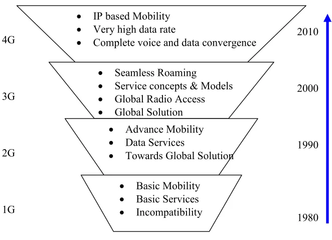
There are three different generations as far as mobile communication is concerned. The first generation, 1G, was established in the mid 1980s. 1G is a semi analogue mobile network because it uses an analogue radio path with digital switching. The most popular 1G mobile networks are Nordic Mobile Telephone Systems (NMT) and American Mobile Phone Systems (AMPS) [13, 14]. These networks provide only basic services (such as speech and speech-related) for users. 1G networks have national specifications. Therefore, 1G networks are incompatible with each other.
this is that these networks are mainly designed to deal with circuit switch voice and each channel is dedicated to only one user.
The General Packet Radio Service (GPRS) has been developed to address these issues by providing the packet switch bearer service. GPRS applies packet radio principles to efficiently transfer data between GSM mobile stations and external packet data network. GPRS provides connection set up time of 1 second and data rates up to several tens of Kbits/s.[13] (The theoretical maximum GPRS data rate is 171.2 Kbps per channel.)
The 3G can be considered as the next step beyond GPRS. The third generation is expected to complete the globalization process of mobile communication. Universal Mobile Telecommunication Systems (UMTS) and CDMA-2000 are the two main 3G networking standards. The emphasis of this thesis is on UMTS which has been approved as the standard for the UK and other European countries by the European Telecommunications Standards Institute (ETSI) [15]. UMTS is the third generation of cellular networks, offers advanced features such as: high data rate (144 Kbps for satellite and rural outdoor, 384Kbps for urban outdoor, 2Mbps for indoor and low range outdoor) and improved QoS services to users. UMTS also provides better frequency efficiency and lower transport costs using ATM network for both voice and data services.
UMTS provided a platform to combine different services such as: speech and data with the Internet. From a commercial point of view, UMTS creates a global market for mobile multimedia with vast opportunities for new revenues, such as:
Providing a wide variety of new multimedia and entertainment services
Offering personalized news and information
Providing a targeted advertising channel and stimulating income from Web referrals
Deploying services that facilitate transactions
4G
3G
2G
1G
1990 2000
1980 2010
• IP based Mobility
• Very high data rate
• Complete voice and data convergence
• Seamless Roaming
• Service concepts & Models
• Global Radio Access
• Global Solution
• Advance Mobility
• Data Services
• Towards Global Solution
• Basic Mobility
• Basic Services
[image:34.595.156.487.84.323.2]• Incompatibility
Figure 2-1: Summary of the functionality of different generations of mobile networks
2.2.1. UMTS
2.2.1.1. Architecture
As illustrated in Figure 2-2, a UMTS network consists of three domains: Core Network (CN), UMTS Terrestrial Radio Access Network (UTRAN) and User Equipment (UE) [14].
Core Network (CN): The CN includes physical entities to provide
Node B Node B
RNC
Application Servers
RNS
Node B Node B
RNC RNS
UTRAN
User Equipment
SGSN
GGSN
IMS
MSC
GMSC
HSS
Core Network
CN PS Domain CN CS Domain
RAS
WLAN
CSCF
[image:35.595.143.483.69.513.2]HSS
Figure 2-2: UMTS architecture
UMTS Terrestrial Radio Access Network (UTRAN): UTRAN consists of RNCs and Node-Bs, which are shown in section Figure 2-2.
2.2.1.2. UMTS Components
The components of UMTS architecture are as follows:
GGSN (Gateway GPRS Support Node): Provides access to the services area over the Internet
SGSN (Serving GPRS Support Node): Provides the functions of network access node and mobility management
IMS (IP Multimedia System): Responsible for delivering internet services over GPRS. It supports other networks and provides an open standards-based network that delivers integrated multimedia services.
MSC (Mobile Switching Centre): Contains connection management
functionality. The MSC server is also responsible for mobile management and contains the VLR (Visitor Location Register).
HSS (Home Subscriber Server): Is an evolution of the Home Location
Register. HSS provides storage for relevant information for both GSM and UMTS subscribers. HSS has two parts: User Profiles and User Locations.
GMSC (Gateway Mobile Switching Centre): works as a gateway
between PLMN (Public Land Mobile Network) and PSTN (Public Switched Telephone Network) in order to provide the necessary signalling and convert traffic formats between two networks. For mobile terminated calls, it interacts with the HSS to obtain routing information.
RNS (Radio Network Subsystem): Contains one RNC and is responsible
for the resources and Transmission/Receiving in a set of cells.
RNC (Radio Network Controller): Enables autonomous Radio Resource Management (RRM) by UTRAN and is responsible for controlling the use and integrity of the radio resources. RNC also assists in the soft handover of UEs when a UE moves from one cell to another.
2.2.2.WLAN
Wireless LAN technology has evolved to extend LANs, which was emerged during 1970s to enable sharing of expensive resources such as printers and to manage the wiring problem caused by increasing number of terminals in offices. By the early 1980s, three standards for LAN were developed: Ethernet (IEEE 802.3), Token Bus (IEEE 802.4) and Token Ring (IEEE 802.5); they each specified distinct physical (PHY) and medium access channel (MAC) layers and different topologies for networking. Currently, LANs are mostly based on switched Ethernet technology that consists of an interconnection of hosts and routers. The 802.11 [16] industry standard and its various revisions are a particular form of Wireless LAN. 802.11 WLAN is commonly referred to as “Wi-Fi” (Wireless Fidelity). The IEEE802.11 Working Group was formed in 1990 to define standard physical (PHY) and medium-access control (MAC) layers for WLANs in the publicly available ISM (Industrial, Scientific and Medical) bands. The original goal was to have data rates of 2Mbps, falling back to 1 Mbps in the presence of interference or if the signal became too weak.
Since then, several task groups (designated by letters) have been created to extend the IEEE 802.11 standard. Task groups 802.11b [17] and 802.11a [17] have completed their work by providing two relevant extensions to the original standard. The 802.11b task group produced a standard for WLAN operations in the 2.4 GHz band, with data rates up to 11Mbps. This standard, published in 1999, has been very successful in its deployment in public places. The 802.11a task group created a standard for WLAN operations in the 5GHz band, with data rates up to 54Mbps. Among the other task groups, it is worth mentioning task group 802.11e (which propose algorithms to enhance the MAC with QoS features to support voice and video over 802.11 networks) and task group 802.11g (which is working to develop a 54Mbps data rate extension to 802.11b at 2.4 GHz).
Internet). Data rates for WLAN systems typically vary from 1 Mbps to more than 100 Mbps.
Wireless LAN systems may be used to provide service to visiting users in specific areas (called “hot spots”). Hot spots are geographic regions or service access points that have a higher amount of usage than average. Examples of hot spots include wireless LAN (WLAN) access points in a trains, buses, railway stations and coffee shops.
2.2.2.1. WLAN Components
End User Access Devices (Stations): End user access devices are called stations (STA) in a WLAN system. End user stations are transmitter and receiver that convert radio signals into digital signals that can be routed to and from communication devices.
Access Points (APs): An access point (AP) is a radio access transceiver
(combined transmitter and receiver) that is used to connect wireless data devices (stations) to a Local Area Network (LAN) system. Access points convert and control the sending of data packets and can connect one or many wireless devices to a wired LAN[16]. Access points can perform one or many types of data transfer functions including bridging (linking networks), retransmitting (repeating), distributing (hubs), directing packets (switching or routing) or to adapt formats for other types of networks (gateways).
Gateway: Gateways are communications devices or assemblies that
transform data that is received from one network into a format that can be used by a different network. Wireless gateways are access points that can assign temporary IP addresses (DHCP) to nodes and have the ability to share a single public IP addresses with several private IP addresses.
2.2.3.Wireless Metropolitan Area Network (WMAN)
applications include interconnecting law-enforcement, public utility, or public safety communication services.
With the introduction of Broadband Wireless Access (BWA) technology, WMANs can be used to provide broadband access to public users in an urban area. This allows WMAN systems to compete with other technologies such as Digital Subscribe Line (DSL) and cable modems.
To develop a cost effective, high-speed data transmission WMAN system, the IEEE created the 802.16 [18]. The 802.16 systems is a line of sight system that operates in the 10 to 66 GHz of radio spectrum. WiMAX (World Interoperability for Microwave Access), based on the IEEE 802.16 standard, is aimed to provide wireless data over long distances, in a variety of different ways, from point to point links to full mobile cellular type access.
2.3.
OSI reference model and mobility management
The OSI reference model breaks the communication into seven layers. Each layer has a well-defined scope of its functions clearly. When it comes to mobility management, there are techniques that can be used at each layer. This section gives a brief overview of these techniques.
Physical Layer: this layer transmits the bit stream over an interface or media between sender and receiver. The air interface in wireless communication is responsible for carrying radio signals and finally the data from sender to receiver antennas.
Data Link Layer: is responsible for specifications of the logical
Network Layer: this layer provides switching and routing technologies. Addressing, internetworking, error handling, congestion control are the other function of third layer of OSI reference model. Network layer in mobile networks besides the addressing and care of MN addressing is responsible for location and handover management. Mobile IP (MIP) [1] is one of the most important protocols for macro mobility management and Hierarchical Mobile IP (HMIP)[19] is a sample for Micro-mobility roaming.
Transport Layer: this layer is responsible for transparent transfer of data between two end systems. This layer provides error recovery and flow control and the key differences with network layer is that transport layer is end-to-end while network layer is a point-to-point chain between routers. This layer also can provide functionality for multi-homing and handover management in mobile networks. mSCTP[20] is an example of a handover management protocol in this layer that uses the multi-homing feature of SCTP to handle micro and macro mobility. Mobile SCTP (mSCTP) [21] is the new extension of SCTP that uses the multi-homing feature of SCTP to manage handover in wireless networks. The mSCTP needs to use a location management protocol like Mobile IP (MIP) [1], Session Initiation Protocol (SIP) [22] or any other location management protocol to complete the mobility management process, the details of this is explained in the next chapter and further information is available in [23 2006].
Session, Presentation and Application Layers: these layers which mostly recognised as application layer support applications and end users’ processes. Authentication, Authorization and Accounting (AAA) that are part of security in computer networks is part of the tasks in these layers. In mobile communication, this layer can perform a role in handover management and location management. Session Initiation Protocol (SIP)[22] is an example of location management that operates in this layer.
2.4.
Application based terminal mobility
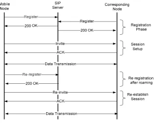
Session Initiation Protocol (SIP) is the main mobility management protocol in application layer, specified in IETF RFC–3261 [22]. SIP can establish, modify and terminate multimedia sessions. The main function of SIP is to establish real-time calls and conferences over internet-protocol networks. Each session may include different types of data, such as audio and video, although currently most SIP extensions address audio communication. [24]
SIP defines a number of components, namely user agents (application that initiates the SIP request), redirect servers (gives the client information about the next hops the message should take), proxy servers (receives SIP messages from a client or another proxy server and forwards the messages to the next SIP server in the network) and registrars (deals with current-location of user agent registration). SIP inherently supports personal mobility and can be extended to support service and terminal mobility. Terminal mobility allows a device to move between IP sub-nets, while continuing to be reachable for incoming requests and maintaining sessions across subnet changes. Mobility of hosts in heterogeneous networks is managed by using the terminal mobility support of SIP.
Figure 2-3: SIP signalling
SIP suffers from some drawbacks[25]. Firstly, the SIP session must be setup completely while the mobile terminal is in the overlap area of the cells to avoid connection disruption. Secondly, mobile node should acquire the IP address via DHCP that can increase the handover delay.
2.5.
Transport layer based mobility
novel transport layer solution for dealing with random link failures in mobile networks.
Multi-homing is a concept that has been gaining more interest in the research communities [12]. Multi-homing addresses the problem of single point of failure by using the alternative connections. This feature provides both endpoints with multiple communication paths and thus the ability to failover (switch) to an alternative path when the link failure occurs. The simultaneous connectivity can be realised using multiple ISPs or multiple wireless access technologies, such as cellular networks (e.g. GPRS, UMTS) and wireless LANs and MANs (e.g. 802.11, WiMAX).
The current transport protocols, TCP and UDP, do not support multi-homing. TCP allows binding to only one network address at each connection ends. This is the main reason why a new transport-layer protocol, Stream Control Transmission Protocol (SCTP) [3], is being investigated in this research. SCTP is a general purpose transport layer protocol providing reliable ordered delivery of data (like TCP) and also unreliable data message (like UDP). SCTP also featured with multi-homing and multi-streaming capabilities.
2.5.1. SCTP
To appreciate the functionalities of SCTP, a comparison between SCTP, TCP and UDP is presented in Table 2-1.
Protocol Feature SCTP TCP UDP
Reliable data transfer Yes Yes No
Partial reliable data transfer Yes No No
Connection oriented delivery Yes Yes No
Congestion control and avoidance Yes Yes No
Path MTU discovery and message fragmentation
Yes Yes No
Message bundling Yes Yes No
Multi-homing Yes No No
Multi-streaming Yes No No
Ordered data deliver Yes Yes No
Unordered data delivery Yes No Yes
[image:44.595.110.504.145.406.2]Path reachability check Yes No No
Table 2-1: A summary of SCTP, TCP and UDP functionalities[27]
An SCTP connection, called association, includes two major new capabilities, multi-homing and multi-streaming.
2.5.1.1. Multi-homing
A host is called multi-homed if it is reachable or accessible through multiple IP addresses. This feature of SCTP, multi-homing, allows for binding of one transport-layer association to multiple IP addresses, which makes an SCTP sender capable of sending data to a multi-homed receiver through different destination addresses as illustrated in Figure 2-4. Therefore, if one of the IP addresses becomes unreachable, which could happen due to link failure as MN is too far from an access point, failing in ISP or failing in host’s interface, the destination host can still receive data through an alternative interface.
built-in failure detection and recovery system, known as failover, which allows associations to dynamically send traffic to an alternate peer IP address when needed. SCTP’s failover mechanism is static and does not adapt to application requirements or network conditions.
As a TCP connection uses a single IP address at each end host, the possible connections between host A and B, in Figure 2-4, are (A1,B1), (A1,B2), (A2,B1) or (A2,B2). SCTP connection allows association between all available IP addresses at each end point. Hence, an SCTP association between host A and B could consist of two sets of IP addresses: {(A1, A2), (B1, B2)}.
Host A
A1A2
Host B
B1B2
Internet
ISP
ISP
ISP
ISP
Figure 2-4: Multi-homing Scenario
This feature of SCTP is currently used for redundancy or fault tolerance. If one destination address becomes unreachable, the destination can still send and receive via other interfaces bound to the association. When the peer is multi-homed, an SCTP endpoint will normally be required to select one of the peer’s destination addresses as the primary destination address. All other destination addresses or associations of the peer become alternate or backup addresses. The endpoints periodically check the availability and reachability of the links. In SCTP signalling, HEARTBEAT chunks are responsible for keeping the reachability status up-to-date [3].
2.5.1.2.Multi-streaming
Another important feature of SCTP is multi-streaming. In a TCP connection, all bytes received must be processed in the same order they were sent. For instance, if a segment is transmitted first, it must safely arrive at the destination before a second message can be processed even if the second segment arrives earlier. SCTP has the ability to process multiple segments (in any order of arrival) by sending segments in different streams. Therefore, SCTP distinguishes different streams of messages within one SCTP association.
Figure 2-5 shows a multi-streamed association between hosts A and B. During this example, host A requested three streams to host B (numbered 0 to 2), and host B requested only one stream to host A (numbered 0).
Figure 2-5: Multi-streaming Scenario
The multi-streaming allows independent delivery among data stream. Application data can be portioned into multiple streams. These portions or data chunks will be formed inside an SCTP packet and each packet can contain multiple data chunks from different applications. Chunks header contains Transmission Sequence Number (TSN), Stream ID and Stream Sequence Number (SSN) that can provide independent delivery of each stream to the application.
retransmission or failover purposes. Also, the functionality of multi-streaming allows different applications to handle via separated streams. This will solve the Head-of-Line (HoL) Blocking drawback of TCP that uses only one stream per communication link. Therefore in SCTP, if data on Stream 1 (S1) is lost, only Stream 1 is blocked at the receiver while waiting for re-transmission and other streams can still carry on the transmission without and disruption on their delivery.
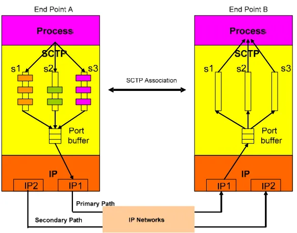
Figure 2-6: SCTP association with both multi-streaming/multi-homing features (End point A is a Sender and B is a receiver)
2.5.2.Mobile SCTP (mSCTP)
With the help of the dynamic address reconfiguration, the SCTP with the ADDIP extension (called mSCTP[8, 20]) would provide soft handover for the mobile terminals without any additional support of routers/agents in the networks. The ADDIP extension enables the SCTP to add, delete and change the IP addresses during active SCTP association. In this scheme SCTP with ADDIP takes care of handover and provides a soft and seamless roaming and a location management protocol like MIP or SIP is used for keep tracking of the MN movements.
parameters, two additional chunks, Address Configuration Change Chunk (ASCONF) and Address Configuration Acknowledgment (ASCONF-ACK) are defined [7].
Figure 2-7 shows the ASCONF chunk format involved in DAR [7]. The Type field is filled with the value, 0xC1, to identify ASCONF chunk and the Flag field sets to 0 as it is not used in this chunk. The Chunk length field denotes the length of the chunk and serial number is used in order to distinguish a particular ASCONF chunk from other chunks. Address parameter is set to a sender address. ASCONF parameter fields contain add-IP, delete-IP, and set-primary-IP parameters.
Figure 2-7: ASCONF Chunk Format
ASCONF parameters are formed in the shown structure in Figure 2-8. Type field gets the value of 0x001, 0x002, 0x004 for add-IP, delete-IP, and set-primary-IP parameters respectively. Length is the size of parameter, which depends on the address parameter length. The address parameter length as described in subsection 3.3.2.1 of RFC2960 is 8 bytes for IPv4 and 20 Bytes for IPv6. ASCONF-request correlation ID is used for a sender of the ASCONF chunk to distinguish the particular chunk from other chunks.

![Table 2-1: A summary of SCTP, TCP and UDP functionalities[27]](https://thumb-us.123doks.com/thumbv2/123dok_us/1604961.113374/44.595.110.504.145.406/table-summary-sctp-tcp-udp-functionalities.webp)