Space-based geoengineering: challenges
and requirements
C R McInnes
Department of Mechanical Engineering, University of Strathclyde, Glasgow G1 1XJ, UK. email: [email protected]
The manuscript was received on 11 November 2008 and was accepted after revision for publication on 15 September 2009.
DOI: 10.1243/09544062JMES1439
Abstract: The prospect of engineering the Earth’s climate (geoengineering) raises a multitude of issues associated with climatology, engineering on macroscopic scales, and indeed the ethics of such ventures. Depending on personal views, such large-scale engineering is either an obvious necessity for the deep future, or yet another example of human conceit. In this article a simple climate model will be used to estimate requirements for engineering the Earth’s climate, princi-pally using space-based geoengineering. Active cooling of the climate to mitigate anthropogenic climate change due to a doubling of the carbon dioxide concentration in the Earth’s atmosphere is considered. This representative scenario will allow the scale of the engineering challenge to be determined. It will be argued that simple occulting discs at the interior Lagrange point may represent a less complex solution than concepts for highly engineered refracting discs proposed recently. While engineering on macroscopic scales can appear formidable, emerging capabili-ties may allow such ventures to be seriously considered in the long term. This article is not an exhaustive review of geoengineering, but aims to provide a foretaste of the future opportunities, challenges, and requirements for space-based geoengineering ventures.
Keywords: macroengineering, geoengineering, climate change
1 INTRODUCTION
Human civilization has developed during a time when the climate has been in a relatively benign state, with modern civilization quickly developing during a tem-perate period between extremes. These favourable circumstances have allowed rapid global population growth combined with relative affluence in the West. However, the recent controversy surrounding human-driven climate change has brought into sharp focus the fact that the climate is not static. The popular view of the climate as being perpetually in equilibrium is only due to the narrow window of human history through which we view the past.
Natural climate variability has been a major driver in the long-term expansion of human activity. Histor-ically, population growth, migration, and the devel-opment of technology have been, at least partly, in response to the driver of climate variability and its influence on the complex web of human activities. However, as modern industrial society becomes more sophisticated and integrated, future climate variability
will likely have a more profound influence than has been the case in the past. For example, if a period similar to the ‘little ice age’ of 1645–1715 [1] were to recur in western society, the resulting change in energy demand would have major consequences for energy prices and possibly economic stability. Aside from such relatively recent and geographically localized events, there is of course significant long-term vari-ability in the Earth’s climate. The advance and retreat of ice sheets appears to be forced by the Milankovitch cycles, which can trip the climate into periodic ice ages through stochastic resonance [2].
dioxide concentration from a pre-industrial value of 280–560 ppm will lead to an increase in mean global temperature of order 1.75 K [3], although some studies indicate more significant warming [4]. Proxy records appear to show that the mean global temperature has already risen by 0.6±0.2 K during the last century, although there is still debate as to the appropriate use of such data [5]. As will be seen in section 3.2, a dou-bling of carbon dioxide concentration is estimated to require a reduction in total solar insolation of order 1.8 per cent to mitigate its effects.
Most attention and effort has been focused on emission reductions in order to minimize the peak concentration of carbon dioxide later in this century. While such approaches have dominated the debate on anthropogenic climate change, there is a grow-ing discussion of engineergrow-ing solutions, which can be deployed in addition to emission reductions, or as an alternative method of mitigation should emission con-trols prove to be politically unobtainable. While even the discussion of such geoengineering solutions can be controversial, it seems prudent to investigate geo-engineering both as an effective tool to mitigate the effects of short-term anthropogenic climate change, and perhaps more importantly, as a tool to deal with the extremes of long-term natural climate variabil-ity [6–8]. It should be noted that given the global effects of geoengineering, serious political issues will of course arise concerning any future deployment.
Last, it should be noted that simple climate mod-els can possess multiple, overlapping equilibria with the same forcing from solar insolation [9]. These mod-els help explain the fact that the climate can switch rapidly between different states and is sensitive to rel-atively small changes in solar insolation driven, for example, by the Milankovitch cycles. The intriguing possibility then arises that the complexity of the cli-mate can be actively exploited, so that geoengineering can be deployed in a more subtle and sophisticated manner than has been considered in the past. By exploiting the non-linearity of the climate, it may be that geoengineering schemes can be considered which can actively control such transitions between climate states using only modest, localized engineering inter-vention. This is an exciting possibility for the future, which may significantly reduce the scale of endeavour required compared to the macro-engineering schemes discussed here.
2 GEOENGINEERING
2.1 Climate response
The definition of geoengineering is open to inter-pretation, since it can be argued that the industrial release of carbon dioxide and other emissions is a form of geoengineering, given the likely climatic change
that it will bring about. However, geoengineering will be used here as a term to describe deliber-ate, active intervention to modify the climate in a controlled manner, with presumed beneficial effect. It will be assumed that space-based geoengineering schemes can be slowly deployed over a period as long as 100 years, either to directly mitigate the effects on the climate of an unconstrained rise in carbon dioxide emissions or to spread terrestrial mitigation costs by allowing a gradual conversion to low carbon technologies.
While geoengineering has a long history in various guises [8], it is only relatively recently that space-based geoengineering using orbiting solar reflectors has been considered (although as early as 1929 Oberth discusses the use of reflectors for localized climate engineering [10]). While only large-scale ventures are investigated here, there are a range of other measures available including active carbon capture and seques-tration from fossil fuels, natural carbon sequesseques-tration through ocean fertilization, cloud formation, modifi-cation of surface albedo through ice cover, and land use and the control of atmospheric emissivity through long-lived radiatively active gases (including carbon dioxide) [8].
Critics of geoengineering have argued that a coarse modification of total solar insolation will lead to a range of undesirable consequences. In particular, it has been argued that while carbon dioxide traps heat during both the day and night cycles, a reduction in solar insolation will only be experienced during the day cycle. In addition, the averaged effect of such geoengineering would be most pronounced at the equator, leading to a less distinctive diurnal cycle and lower temperature gradients with latitude.
2.2 Terrestrial geoengineering schemes
Most proposals for large-scale geoengineering involve modifying total solar insolation through scattering sunlight back to space. A range of strategies have been proposed to mitigate anthropocentric climate change, including large-scale deposition of scattering aerosols in the stratosphere on a global scale, either sulphur dioxide particles [8,13] or di-electric aerosols [14,15]. Early proposals by Budyko (as described by Keith [7] and Schneider [8]) estimated that approximately 107
tonnes of sulphur dioxide per annum are required to offset a doubling of carbon dioxide concentration, while Teller et al. [14, 15] estimated that approxi-mately 107tonnes per annum of∼100 nm aerosols are
required to increase the Earth’s albedo by 1 per cent. Telleret al.also demonstrated that by using optically resonant scattering particles the mass requirements for such a venture could be reduced to 105–106tonnes
per annum, with either mesh microstructures or vast numbers of small 4-mm helium-filled aluminium bal-loons sized to float to 25 km, with a long life in the stratosphere, but oxidizing rapidly in the troposphere. Recent estimates by Crutzen identify a requirement for 1–2×10⁶tonnes of sulphur per annum deposited
in the stratosphere from balloons in the tropics [13]. Climate cooling following major volcanic erup-tions, such as Mount Pinatubo in 1991, demonstrates that such active control is possible, although engi-neered ventures would of course be significantly better optimized. The Pinatubo eruption deposited an esti-mated 1.7×10⁷tonnes of sulphur dioxide into the
atmosphere, leading to a mean hemispheric surface cooling of order 0.5 K [16]. The climate cooling from the Pinatubo eruption is likely to have been greater than the effective warming from anthropogenic car-bon dioxide during 1991–1993. However, there are concerns that large-scale deposition of engineered aerosols may lead to changes in atmospheric chem-istry, in particular enhancing ozone depletion and the production of acid rain from sulphates.
Other promising, near-term geoengineering sche-mes include the exploitation of the Twomey effect, proposed by Latham and Salter to increase the reflec-tivity of low-level ocean clouds [17]. Automated ocean vessels would spray fine salt aerosols to generate nucleation centres for cloud formation. A combina-tion of the mocombina-tion of the vessels and atmospheric circulation would ensure good spatial coverage. A fleet of some 1500 wind-driven vessels is estimated to be required with each vessel mass of order 300 tonnes, yielding a total system mass of order 5×10⁵tonnes.
2.3 Space-based geoengineering schemes
Aside from aerosol deposition (albedo modifica-tion) and carbon sequestration (atmospheric emis-sivity modification), large-scale geoengineering using
orbiting reflectors has been considered by various authors to manipulate the total solar insolation [18–24]. These concepts centre on fabricating and deploying a large occulting disc (or many smaller discs) to reduce the total solar insolation in order to mitigate increased carbon dioxide emissions. For example, the use of vast numbers (∼5×10⁴) of
100 km2, actively controlled occulting discs in the
Earth’s orbit has been considered, but would likely lead to an apparent flickering of the Sun (∼2 per cent ampli-tude) and would create a significant orbital debris hazard [7]. In addition, various proposals for an artifi-cial ring of passive scattering particles in the Earth’s orbit have been documented with a mass of order 2×10⁹tonnes [21,25]. A recent addition to this class
of concepts is the use of clouds of dust grains located at the stable Earth–Moon triangular Lagrange points L4andL5[26]. In this scheme of order 2×10¹¹tonnes
of lunar or cometary dust is deposited in the Earth– Moon system forming clouds at L4 and L5. As with
other occulting schemes, the dust would lead to a reduction in solar insolation to offset radiative forc-ing by carbon dioxide. However, since each cloud only reduces solar insolation for a relatively short period each month, when the cloud is between the Earth and the Sun, significant mass is required to ensure a large optical depth and so useful cooling on average.
A perhaps more effective scheme is to station a large occulting disc (or discs), typically with a total mass of order 107–108tonnes, close to the Sun–EarthL
1
(Lagrange) equilibrium point some 1.5×10⁶km
sun-wards of the Earth. The equilibrium location at theL1
point is unstable, necessitating the use of active con-trol using solar radiation pressure. Indeed, the use of a large numbers of smaller occulting discs proposed by McInnes would mitigate the potentially catastrophic effect of the loss a single large disc [23].
The use ofL1for geoengineering has been recently
revisited by Angel who proposes swarms of engineered thin film refractive (rather than reflective) discs with a total mass of order 2×10⁷tonnes [24]. Rather than
directly reflect solar radiation, the refracting discs scat-ter sunlight to avoid the Earth’s disc, but are highly engineered thin film devices that require terrestrial fabrication and launch at extremely high cost. How-ever, it is possible that much simpler partly reflecting discs could be fabricated in-situ from near-Earth asteroid resources [23]. There is a trade-off between the total mass of a geoengineering scheme and the engineering challenge of fabrication and deployment, as will be discussed later in section 5.
advantages, there are clearly challenges associated with the fabrication and active control of such large, gossamer structures. Again, it is almost certain that such structures would be fabricated in-orbit, either using lunar material or material processed from a suit-able near-Earth asteroid. Therefore, a prerequisite for space-based geoengineering is the capability to effec-tively and economically exploit the resources of the moon or asteroids. The issues associated with the fab-rication of large solar reflectors will be discussed later in section 5.
3 CLIMATE DYNAMICS
3.1 Energy balance model
In order to determine the requirements for geoengi-neering, it is necessary to investigate the response of the Earth’s climate to large-scale engineering inter-vention. In particular, the response of the global mean temperature to changes in total solar insola-tion is of interest, as are any non-linear effects that would pose a risk of unintended and potentially catas-trophic modifications to the climate. By determining an approximate relationship between global mean temperature and solar insolation, the requirements for space-based geoengineering can be estimated and the scale of the venture can be determined. The energy balance model (EBM) is an extremely simple climate model that captures the essential large-scale features of the Earth’s climate dynamics [28]. This low-order (so-called zero-dimensional) model clearly does not contain the sophistication of numerical general cir-culation models, but does allow insights into the underlying processes at work. The EBM assumes that any change to the heat balance of the Earth is sim-ply due to an inequality between absorbed heat flux QIN and emitted heat flux QOUT. Therefore,
assum-ing some mean specific heat capacityCper unit area and global mean temperatureT, the dynamics of the Earth’s climate can be written simply as
CdT
dt =QIN−QOUT (1a)
so that CdT
dt =Q(1−α)−εσT
4 (1b)
where Q (342.5 W/m2) is the total solar insolation,
α (∼0.3) is the mean planetary albedo, ε is the mean atmospheric emissivity (∼0.62), andσ (5.67× 10⁻⁸W/m2/K4) is the Stefan–Bolztman constant [28]. It
should be noted that the solar insolation is defined in terms of the solar constantF(1370 W/m2) asQ=F/4,
since the Earth presents only a circular cross-sectional area to the incoming flux but radiates over its entire spherical surface area. Assuming that the climate is in
equilibrium(dT/dt =0), a naive initial estimate of the Earth’s mean temperature can be obtain from equation (1b) as
¯ T =
Q(1−α)
εσ
1/4
(2)
which yields an estimated mean temperature of 14.0◦C (287 K), in good agreement with the observed
global mean temperature. In order to provide a more accurate EBM, an empirical relationship that models the emitted heat flux QOUT can be used. This more
complete EBM can then be written as
CdT
dt =Q[1−α(T)] −A−BT (3) where the coefficients forQOUT are determined from
empirical observational data as A=204 W/m2 and
B=2.17 W/m2/K [28]. Again, assuming that the
cli-mate is in equilibrium (dT/dt=0), a new estimate of the Earth’s mean temperature can be found from equation (3) as
¯
T = Q(1−α)−A
B (4)
This new estimate of the global mean temperature is found to be 16.5◦C (289.5 K), which is again in good
agreement with the observed global mean tempera-ture. Again, the EBM is used here solely to provide an estimate of the scale of geoengineering required.
3.2 Climate cooling
As discussed in section 1, it is generally agreed that there has been an increase in the global mean tem-perature of order 0.6±0.2 K during the last century. This rise in global mean temperature is specifically due to a significant increase in radiatively active gases in the atmosphere, principally carbon dioxide, leading to a reduction in the effective emissivity of the atmo-sphere. The reduction in emissivity can be expressed as a change in radiative forcing. For a doubling of the car-bon dioxide content in the atmosphere it can be shown that the coefficientAis reduced by 4.17 W/m2,
result-ing in lower re-radiation of heat due to an enhanced greenhouse effect [3]. It is noted that more recent esti-mates of forcing are of order 3.7 W/m2. However, Angel
[26] also uses the data from reference [3] and so the same forcing is used here to allow for direct compar-ison. In principle, this change in radiative forcing can be offset by a reduction in the effective solar insola-tion through geoengineering. From equainsola-tion (4), the required change in solar insolation δQ to offset a change in radiative forcingδAwhile maintaining the same mean global temperature is given by
δQ=Q−B ¯
T+(A−δA)
Therefore, using equation (5) the simple EBM shows that to maintain the mean temperature of 17◦C (290 K)
in the presence of a doubling of the carbon diox-ide content of the Earth’s atmosphere, a reduction in solar insolationδQ/Qof 1.7 per cent is required. The requirements to engineer such a reduction in effective solar insolation will be determined later in section 4. Again, it is noted that numerical studies of the effect of geoengineering have demonstrated that reducing solar insolation appears to compensate for increased atmospheric carbon dioxide, significantly ameliorat-ing increases in global mean temperatures [3,11,12]. Assuming that such a reduction in solar insolation δQcan be engineered, the response of the mean global temperature can be obtained from equation (3). If the change in insolation is small, so that the albedo is fixed, there is a change in mean global temperature such that
T(t)= ¯T+δQ B (1−α)
1−exp
−t
τ
(6)
where τ =C/B is the relaxation time of the system. By considering the heat capacity of the top 70 m of the oceans (mixing layer), it is found thatτ ∼3 years, so that the response of the climate to changes in insolation is slow, but at an acceptable time scale for a geoengineering venture. For t ≫τ the result-ing change in mean global temperature is of order (1−α)δQ/B, so that a reduction in solar insolation δQ/Q of 1.7 per cent to offset a doubling of the car-bon dioxide content of the atmosphere is equivalent to reducing the mean global temperature by approx-imately 2 K. The requirements to engineer such a reduction in solar insolation using a large occulting disc (or discs) will be considered in the next section.
4 ENGINEERING REQUIREMENTS
4.1 Occulting solar discs
The concept of using a large occulting disc (or discs) near the Sun–Earth L1 equilibrium point to reduce
solar insolation has been discussed by various authors, as noted in section 2.3. In this section, it will be shown that there is in fact a minimum system mass which can be obtained if the disc is positioned at an opti-mum location along the Sun–Earth line, sunward of the classicalL1Lagrange point. This optimum location
is found from an analysis of the three-body mechan-ics of the problem with the addition of solar radiation pressure on the disc [29]. The location of the disc can be optimized since the solar radiation pressure exerted on the disc will generate a new equilibrium position, sunward of the classicalL1Lagrange point. If the disc
mass is reduced, the solar radiation pressure induced acceleration will increase and so the equilibrium point will be displaced sunward of the classicalL1point [22].
However, as the disc is displaced sunward the required
disc area to maintain the necessary reduction in solar insolation at the Earth will grow, leading to an increase in disc mass. These two processes must then be bal-anced in order to minimize the total disc mass through an optimum choice of disc location.
4.2 Occulter orbit
Now that the required change in solar insolation has been obtained from section 3.1, a suitable occulting disc (or discs) can be sized. For a disc of radius RS
at some distancerSfrom the Earth, the disc will
sub-tend a solid angle S of πR2S/rS2, as shown in Fig. 1.
Similarly the Sun, of radiusROat distancerOfrom the
Earth, will subtend a solid angleOofπRO2/rO2, so that
the disc will partially occult the Sun and reduce the insolation at the Earth by a factor S/O. It should
be noted that by partly occulting the solar disc the solar fluxFis reduced such thatδQ=δF/4; however, the relative change in insolationδQ/Q is identical to the relative change in fluxδF/F. Therefore, the reduc-tion in insolareduc-tion produced by the occulting disc is defined by
δQ Q =
R
S
RO 2r
O
rS 2
(7)
Using equation (7), the required disc radius may now be obtained as a function of its distancerS from
the Earth to provide the required change in solar insolation ofδQ/Qas
RS=RO r
S
rO
δQ Q
1/2
(8)
However, before the occulting disc is sized, the opti-mum distance of the disc from the Earth can be determined to minimize the total disc mass. As dis-cussed in section 2.3, the disc will be located near the
Fig. 1 Occulting solar disc stationed along the Sun– Earth line at an artificial equilibrium point.L1and
[image:5.595.323.557.561.731.2]L1Sun–Earth equilibrium point. However, due to the
solar radiation pressure acting on the disc, the equilib-rium point will be displaced sunward of the classicalL1
point. A trade-off therefore exists between lowering the disc mass and displacing the equilibrium point sun-ward, and ultimately increasing the disc mass due to the increased disc area to provide the required partial occultation of the Sun. This trade-off leads to an opti-mum disc location that will minimize the total mass of the system.
The condition for equilibrium of the occulting disc in the Sun–Earth three-body problem can be deter-mined from a simple force balance. The eccentricity of the Earth’s orbit is neglected as is the lunar gravita-tional perturbation. Although the general solution for artificial equilibria for a reflector is known [29], only a simple one-dimensional problem need be considered here to locate the displaced equilibrium point. Sim-ilarly, it will be assumed that the disc station-keeps close to the Sun–Earth line to provide direct shadow. Since the mass of the EarthMEis essentially
negligi-ble relative to the solar massMO, the centre-of-mass
of the Sun–Earth system will be taken as being located at the centre of mass of the Sun, as shown in Fig. 1. This approximation has a negligible effect on the sub-sequent analysis. The condition for equilibrium may now be obtained by balancing the gravitational force from the Sun and the Earth, the centripetal force and the solar radiation pressure induced acceleration experienced by the occulting discaSsuch that
GME
r2 S
− GMO (rO−rS)2
+ω2(rO−rS)+aS=0
ω=
GMO
r3 O
(9) whereωis the orbital angular velocity of the Earth rela-tive to the Sun andGis the gravitational constant. The inverse square solar radiation pressure induced accel-eration experienced by the occulting disc of massMS
and areaASmay be written as
aS =
2κPEAS
MS
r
O
rO−rS 2
(10)
where PE (4.56×10⁻⁶N/m2) is the solar radiation
pressure experienced by an absorbing surface at 1 astronomical unit (rO) and κ is a function of the
optical properties of the disc. It can be shown [30] that for a specular reflector with Lambertian thermal re-emission the functionκis given by
κ =1 2
(1+η)+2 3(1−η)
εF−εB
εF+εB
(11)
whereηis the specular reflectivity,εFis the emissivity
of the front (Sun facing) side of the disc, andεBis the
emissivity of the rear (Earth facing) side of the occult-ing disc, while the disc has an area AS of πRS2. Using
equations (8) and (10), the disc massMSmay now be
written as
MS(rS)=2πκPER2O
δQ
Q
rS
rO−rS
2 1
aS(rS)
(12)
where aS is determined from equation (9). Since
equation (12) is now a function ofrSonly, the variation
of the mass of the occulting disc with location along the Sun–Earth line can be investigated to attempt to minimize the disc mass.
4.3 Occulter sizing
The mass of the occulting disc may now be deter-mined for a required reduction in solar insolation. For a fixed disc area, changing the disc mass will alter the solar radiation pressure acceleration experienced by the disc and so will influence the location of the equilibrium point. Assuming a reductionδQ/Qof 1.7 per cent, as discussed in section 3.2, the variation of the disc mass with equilibrium location is shown in Fig. 2, where it can be seen that there are two limiting conditions. First, as the disc is located closer to the classical interior L1 equilibrium point 1.50×10⁶km
from the Earth, the disc mass grows and is unbounded as the classical Lagrange point is approached. This growth in mass is required to reduce the solar radi-ation pressure induced accelerradi-ation experienced by the disc, which would otherwise displace the equili-brium point sunward. Similarly, as the location of the disc is moved sunwards, the required mass of the disc will fall due to the increased solar radiation pressure
Fig. 2 Optimum occulting disc location (κ=0.17). The classicalL1point is at a distance of 1.5 million km
[image:6.595.298.535.540.737.2]induced acceleration required for equilibrium. How-ever, as the disc is moved sunwards significantly from the classicalL1point, its mass will start to grow as the
disc area increases to maintain the required solid angle subtended at the Earth to reduce the total solar insola-tion. These two opposing processes lead to a minimum disc mass, as can be seen in Fig. 2.
The minimum disc mass can now be determined by finding the turning point of equation (12). It can be seen that there is a single location that will minimize the disc mass, independent of the required reduction in solar insolation or the disc optical properties. This location can be found by minimizing the function
f(rS)=
r
S
rS−rO
2 1
aS(rS)
(13)
where it is found that f′(r
S)=0 when the disc
loca-tionrSis 2.36×10⁶km from the Earth. This optimum
location is sunward of the classical interior Lagrange point at 1.50×10⁶km and again is independent of the
disc properties, representing the true optimum loca-tion for an occulting disc (or discs). Assuming that the disc must provide a reduction in solar insolation δQ/Qof 1.7 per cent, a disc with an effective radius of 1450 km (or an equivalent area from a large number of smaller discs) and a total mass of 2.6×10⁸tonne
is required if κ∼0.91, representative of a reflecting metallic occulting disc.
However, ifη∼0 andεF∼0 thenκ ∼0.17,
represen-tative of a non-reflecting black occulting disc, resulting in substantial mass savings, although the optimum location of the reflector remains unchanged. In this case a total mass of 5.2×10⁷tonne is required, again
with an effective radius of 1450 km, as detailed in Tables 1 and 2. A non-reflecting disc could in princi-ple be fabricated using a thin layer of carbon vacuum deposited on a metal film [30]. Forin-situ manufac-turing using a small near-Earth asteroid (discussed in section 5) carbon is readily available. For compari-son, the masses of a range of terrestrial engineering ventures are listed in Table 3. It can be seen that the Chinese Three Gorges Dam requires approximately 6×10⁷tonne of concrete, and so forms a structure
[image:7.595.320.560.99.242.2]with a comparable mass to the occulting disc (or discs). While the challenges posed by space-based geoengi-neering are clearly significant, it interesting to note that measured in terms of mass, such large-scale geo-engineering represents a venture of comparable scale to current large-scale terrestrial engineering ventures.
Table 1 Occulting disc optical properties
Disc type η εF εB κ
A (reflecting) 0.82 0.06 0.06 0.91 B (non-reflecting) 0 0.01 0.5 0.17
Table 2 System level trade-off
Geoengineering concept
Mass
(tonne) Area (km2) Areal density (g/m2)
Struck (LunarL4/5dust
cloud [26])
2.1×10¹¹ – –
Pearson (Earth orbit dust ring [25])
2.3×10⁹ 1.1×10⁸ –
McInnes A (SolarL1
reflecting discs [22,23])
2.6×10⁸ 6.57×10⁶ 40.2
McInnes B (SolarL1
absorbing discs [22,23])
5.2×10⁷ 6.57×10⁶ 7.9
Angel (SolarL1refracting
discs [24])
[image:7.595.319.561.297.375.2]2.0×10⁷ 4.70×10⁶ 4.2
Table 3 Mass comparison with terrestrial engineering ventures
Mass
scale Mass (tonne) Engineering venture
105 6.5×10⁵ ‘Knock Nevis’ oil tanker (fully laden)
106 6×10⁶ Great pyramid of Giza
107 6×10⁷ Concrete used for three Gorges dam
108 2×10⁸ Water stored in London’s reservoirs
109 7×10⁹ World annual CO
2emissions
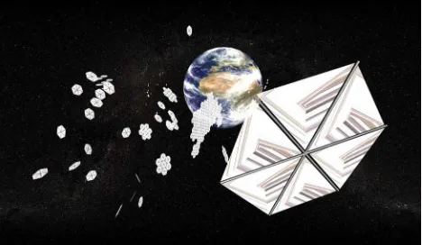
While the analysis above has considered a single occulting disc, a more likely scenario would be the use of a large number of smaller discs with the same total area as that required for a single large disc. Such a swarm of discs may either be independent free-flying elements, or could be used to assemble a large occulter, as shown in Fig. 3. As will be discussed in section 5 below, the mass requirements for an absorb-ing occulter [22,23] (as opposed to highly engineered refractors [24]) necessitates the use of lunar, or more likely near-Earth asteroid material. A scenario can be envisaged whereby individual elements are fabricated
[image:7.595.323.557.585.721.2]from asteroid material and the total effective occult-ing area grows over a period of time (50–100 years), to match the required reduction in solar insolation to maintain a constant global mean temperature as carbon emissions rise. Such a gradual approach to geo-engineering can also be used to reduce the peak costs of terrestrial carbon dioxide mitigation efforts.
5 ENGINEERING CHALLENGES
5.1 Occulter fabrication
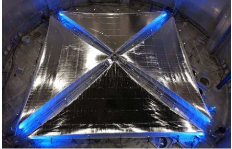
The first steps towards fielding large orbiting solar reflectors are currently taking place through the accelerating development of solar sail propulsion for near-term space science missions [31]. A recent ground-based deployment test of a 20 m×20 m solar sail is shown in Fig. 4. Square solar sails with a side of order 100 m and an areal density of order 5 g/m2 are
foreseen, although concepts exist for both extremely large disc sails (∼1000 m) and low areal densities (∼0.1 g/m2) using thin metallic film. These terrestrially
fabricated reflectors can provide a route towards the fabrication of reflectors fromin-situresources such as near-Earth asteroids.
The use of occulting discs for geoengineering has been discussed in some detail in sections 3 and 4, with a mass of order 5×10⁷tonne required to
off-set a doubling of atmospheric carbon dioxide. Clearly, the fabrication of a swarm of occulting discs with a mass of order 107tonne would require a capability
to exploitin-situresources such as near-Earth aster-oids (although Angel envisages terrestrial fabrication of thin film refracting discs, and hence launch to L1[24]). For example, the mass requirements for the
minimum mass occulting disc (or discs) can be sat-isfied by small M-type asteroids, which are abundant in nickel–iron materials and carbon [32]. A range of
Fig. 4 Completed deployment test of a 20×20 m solar sail to assess the use of storable booms and thin film reflectors (NASA)
novel technologies are currently under investigation to deflect small near-Earth asteroids for hazard miti-gation purposes [33–37]. However, the same technolo-gies could, in principle, be used to capture a small near-Earth asteroid in the vicinity of the L1 point
for subsequent resource extraction, particularly for a small near-Earth asteroid in a low-energy orbit.
It will be assumed that the occulter is fabricated from thin metallic film (possibly with a carbon coat-ing) processed from such a near-Earth asteroid, and that the asteroid has a bulk density half that of iron (7860 kg/m3) to account for the non-metal content.
It is then found that a small M-type asteroid with a radius of only 145 m will provide the required mass for fabrication of the occulting disc (or discs). The asteroid would require to be processedin-situ, prob-ably using solar heating, and the metallic products extruded into thin film for fabrication of the discs. If it is assumed that a modest sized terrestrially fabri-cated solar reflector is initially deployed, then the time required to process the asteroid can be estimated. For example, a 500 m radius disc reflector will intercept a solar flux equivalent to approximately 1 GW of power at 1 astronomical unit. If the disc has an areal density of order 1 g/m2, its total mass is of order 800 kg, well
within the Earth escape capacity of a large commercial launch vehicle. Assuming the asteroid material is lib-erated by focusing this energy to raise the local surface temperature above the melting point of the metallic component (heat of fusion of iron∼2.8×10⁵J/kg), the
maximum rate of production of mass is potentially up to 3.6×10³kg/s resulting in complete processing of
the asteroid on a timescale of order 150 days.
Clearly, there are significant engineering challenges associated with extruding the liberated asteroid mate-rial into thin film, although in principle, thin film fabrication could be automated using vapour depo-sition. The hard vacuum required to allow vapour deposition is already provided by the space environ-ment with the metal vapour condensed onto a cold substrate and separated after rapid cooling. As early as the late 1960s terrestrial laboratory experiments were performed to manufacture thin metal films for solar sails [38]. These initial studies used either a rotat-ing, rigid cylindrical substrate or a flexible rotating band. By altering the speed of rotation of the sub-strate device, and by using masks, the thickness of the metal film could be varied to provide, e.g. addi-tional strength at the edges of the film. Small-scale laboratory processes fabricated coarse films with a thickness of order 10µm. Scaling such a process to
fabricate the required effective area of occulting discs on a timescale of 50–100 years would clearly be a major challenge. For example, fabricating the required area of thin film in 100 years corresponds to a pro-duction rate of order 2000 m2/s. If this is achieved
[image:8.595.37.274.583.735.2]units would be required. Clearly the deployed total mass of such a manufacturing system would be large, but would still be insignificant relative to the mass requirements for direct launch of the swarm of discs from the Earth. Such a gradual approach to geoengi-neering over a 50–100 year timescale can be used to reduce the peak costs of terrestrial carbon dioxide mit-igation costs, in addition to direct compensation for increasing atmospheric carbon dioxide.
5.2 Systems level trade-off
The use of space-based geoengineering has been reviewed and a concept for occulting discs presented with a total deployed mass of 5.2×10⁷tonnes [22,23].
As can be seen from Table 2, this is somewhat more than the scheme proposed by Angel (2×10⁷tonnes)
using terrestrially manufactured refracting discs [24], but significantly less than the dust cloud schemes proposed by Pearson (2×10⁹tonne) [25] and Struck
(2×10¹¹tonne) [26].
Angel proposes a swarm of engineered refractive (rather than reflective) discs with a total mass of order 2×10⁷tonnes [24]. The refracting discs are
highly engineered thin film devices that require ter-restrial fabrication and launch at extremely high cost. McInnes proposes simple occulting discs [22,23] with a total mass of order 5×10⁷tonnes that could be
fabricatedin-situfrom near-Earth asteroid resources. Pearson and Struck propose clouds of coarse dust grains with a mass of 2×10⁹–1011tonnes, which do
not require any form of processing [25, 26]. There is a therefore a trade-off between the total mass of a geoengineering scheme and the engineering challenge and cost of fabrication and deployment. Angel [24] estimates a cost of $50 per kg to man-ufacture highly engineered thin film refracting discs with a further $50 per kg for launch to L1. By using
in-situ resources launch costs are essentially elim-inated, while the use of simple occulting discs or un-processed dust [26] would greatly reduce the spe-cific cost (cost per unit mass), even although the deployed mass may be greater than for engineered refracting discs. Once available, the use of in-situ resources is therefore likely to substantially reduce the cost of space-based geoengineering significantly bellow the $100 billion per year estimate of Angel. Such systems level issues must be addressed in future evaluation of competing geoengineering concepts.
Last, while the costs of such ventures appear daunt-ing at present, a 100 year programme would benefit from accumulated world economic growth. For exam-ple, at the historical average growth rate of world gross domestic product of 4 per cent per annum, the world economy doubles in size every 17 years. A 100 year ven-ture would see a world economy more than 50 times larger at the end of the project than the start.
6 CONCLUSIONS
The aim of this article has been to provide some insights into the possibilities offered by space-based geoengineering using orbiting solar reflectors. While such large-scale macro-engineering clearly requires a leap of the imagination over current large-scale ter-restrial engineering, the natural and human-driven variability of the Earth’s climate will necessitate some form of manipulation of the climate in the long term. Experience obtained from geoengineering may then pave the way towards engineering the climates of other planets, in particular Mars, through so-called terraforming. Again, while the scale of engineering discussed in this article may be daunting, the avail-ability of vast quantities of freely available solar energy in space, and the active control of such energy using orbiting thin film solar reflectors may allow the possi-bility of large scale manipulation of planetary climates. Whether such possibilities are exploited in the future, both to mitigate natural and anthropogenic climate change on Earth and to unlock the resources of space, remains to be seen.
© Authors 2010
REFERENCES
1 Free, M.and Robock, A.Global warming in the con-text of the little ice age. J. Geophys. Res., 1999, 104, 19057–19070.
2 Muller, R. A.and MacDonald, G. J.Glacial cycles and astronomical forcing.Science, 1997,277, 215–218. 3 Govindasamy, B. and Caldeira, K.
Geoengineer-ing Earth’s radiation balance to mitigate CO2 -induced climate change.Geophys. Res. Lett., 2000, 27, 2141–2144.
4 Stainforth, D. A., Aina, T., Christensen, C., Collins, M., Faull, N., Frame, D. J., Kettleborough, J. A., Knight, S., Martin, A., Murphy, J. M., Piani, C., Sexton, D., Smith, L. A., Spicer, R. A., Thorpe, A. J., and Allen, M. R.Uncertainty in predictions of the climate response to rising levels of greenhouse gases.Nature, 2005,433, 403–406.
5 Mann, M. E., Bradley, R. S.,andHughes, M. K. Global-scale temperature patterns and climate forcing over the past six centuries.Nature, 1998,392, 779–787.
6 Cicerone, R. J., Elliott, S., and Turco, R. P. Global environmental engineering.Nature, 1992,356, 9. 7 Keith, D. W. Geoengineering the climate: history and
prospect.Annu. Rev. Energy Environ., 2000,25, 245–284. 8 Schneider, S. H.Earth systems engineering and
manage-ment.Nature, 2001,409, 417–421.
9 Emanuel, K. A simple model of multiple climate regimes. J. Geophys. Res., 2002, 107, ACL 4–1. DOI: 10.1029/2001DJ001002.
10 Oberth, H.Ways to spaceflight, NASA Technical Transla-tion, TT F-622, 1972.
terrestrial biosphere.Geophys. Res. Lett.,2002,29, 18.1– 18.4. DOI: 10.1029/2002GL015911.
12 Lunt, D. J., Ridgwell, A., Valdes, P. J.,andSeale, A. Sun-shade world: a fully coupled GCM evaluation of the climatic impacts of geoengineering.Geophys. Res. Lett., 2008,35, L12710.
13 Crutzen, P. J. Albedo enhancement by stratospheric sulfur injections: a contribution to resolve a policy dilemma?Clim. Change, 2006,77, 211–219.
14 Teller, E., Wood, L., and Hyde, R. Global warming and ice ages: I. prospects for physics based modula-tion of global change, UCRL-231636/UCRL JC 128715, Lawrence Livermore National Laboratory, 1997.
15 Teller, E., Hyde, R., Ishikawa, M., Nuckolls, J.,andWood, L.Active climate stabilization: presently-feasible albedo-control approaches to prevention of both types of climate change. In Proceedings of the Cambridge-MIT Institute Symposium on Macro-engineering options for climate change management and mitigation, Cambridge, 2004. 16 Hansen, J., Lacis, A., Ruedy, R.,andSato, M.Potential
climate impact of Mount Pinatubo eruption.Geophys. Res. Lett., 1992,19, 215–218.
17 Salter, S., Sortino, G.,andLatham, J.Sea-going hardware for the cloud albedo method of reversing global warming. Philos. Trans. R. Soc. A., 2008,366, 3989–4006.
18 Seifritz, W.Mirrors to halt global warming.Nature, 1989, 340, 603.
19 Early, J. T.Space-based solar shield to offset greenhouse effect.J. Br. Interplanet. Soc., 1989,42, 567–569.
20 Hudson, H.A space parasol as a countermeasure against the greenhouse effect.J. Br. Interplanet. Soc., 1991,44, 139–141.
21 Mautner, M.A space-based solar screen against climatic warming.J. Br. Interplanet. Soc., 1991,44, 135–138. 22 McInnes, C. R.Minimum mass solar shield for terrestrial
climate control.J. Br. Interplanet. Soc., 2002,55, 307–311. 23 McInnes, C. R.Planetary macro-engineering using orbit-ing solar reflectors. InMacro-engineering: a challenge for the future, 2006, pp. 215–250 (Springer, Berlin).
24 Angel, R.Feasibility of cooling the Earth with a cloud of small spacecraft near the inner Lagrange point (L1).Proc.
Natl. Acad. Sci., 2006,103, 17184–17189.
25 Pearson, P., Oldson, J., and Levin, E. Earth rings for planetary environment control.Acta Astron., 2006,58(1), 44–57.
26 Struck, C.The feasibility of shading the greenhouse with dust clouds at the stable lunar Lagrange points.J. Br. Int. Soc., 2007,60, 82–89.
27 Mautner, M.and Parks, K.Space-based control of the climate. In Proceedings of the Space 90, 1990, pp. 1159– 1169 (American Society of Civil Engineers).
28 McGuffie, K.andHenderson-Sellers, A.A climate mod-elling primer, 1997 (John Wiley, Chichester).
29 McInnes, C. R., McDonald, A. J. C., Simmons, J. F. L.,and MacDonald, E. W.Solar sail parking in restricted three-body systems.J. Guid. Control Dyn.,1994,17, 399–406. 30 Sanders, D. M., Boercker, D. B.,andFalbella, S.
Coat-ing technology based on the vacuum arc – a review.IEE Trans. Plasma Sci., 1990,18, 883–894.
31 McInnes, C. R.Solar sailing: technology, dynamics and mission applications, 1999 (Springer, London).
32 Gehrels, T.(Ed.).Asteroids, 1979 (University of Arizona Press, Tucson).
33 Melsoh, H. J.Solar asteroid diversion.Nature, 1993,366, 21.
34 Lu, E. T.andLove, S. G.Gravitational tractor for towing asteroids.Nature, 2005,438, 177–178.
35 McInnes, C. R. Deflection of near-Earth asteroids by kinetic energy impacts from retrograde orbits. Planet. Space Sci., 2004,52, 587–590.
36 McInnes, C. R. Near Earth object orbit modification using gravitational coupling.J. Guid. Control Dyn., 2007, 30(3), 870–873.
37 Vasile, M.and Colombo, C. Optimal impact strategies for asteroid deflection.J. Guid. Control Dyn., 2008,31, 858–872.