White Rose Research Online URL for this paper:
http://eprints.whiterose.ac.uk/129175/
Version: Accepted Version
Article:
Gadelha, Hermes Augusto Buarque orcid.org/0000-0001-8053-9249 (2018) The
filament-bundle elastica. IMA Journal of Applied Mathematics. pp. 634-654. ISSN
0272-4960
https://doi.org/10.1093/imamat/hxy011
[email protected] https://eprints.whiterose.ac.uk/ Reuse
Items deposited in White Rose Research Online are protected by copyright, with all rights reserved unless indicated otherwise. They may be downloaded and/or printed for private study, or other acts as permitted by national copyright laws. The publisher or other rights holders may allow further reproduction and re-use of the full text version. This is indicated by the licence information on the White Rose Research Online record for the item.
Takedown
If you consider content in White Rose Research Online to be in breach of UK law, please notify us by
doi: 10.1093/imanum/dri017
The filament-bundle elastica
HERMESGADELHAˆ
Department of Mathematics, University of York,
York YO10 5DD, UK.
Filament-bundles are ubiquitous in nature. They are composed by an assembly of flexible rods held to-gether by elastic springs, such as found in ciliary systems and flagella. We study the static, post-transient, post-buckled configurations of a generalised filament-bundle elastica or flagella. We recur to linear and weakly non-linear analysis, as well as geometrically exact numerical solutions. The bundle cross-linking mechanics is characterised by non-local moments affecting distant parts of the bundle. This induces a bimodal post-buckling response sensitive to the interfilament sliding at the base. We report the occur-rence of a novel reversed cusp catastrophe, reminiscent of the counterbend phenomenon, that folds and suppresses the saddle-node bifurcation back a pitchfork bistability landscape, found in classical elastica systems. The filament-bundle elastica can thus prevent violent jumps, non-uniqueness and hysteresis. This non-trivial folding of the imperfection-sensitivity diagram may impact bundle systems with natu-rally occurring buckling phenomena.
Keywords:
filament-bundle, flagellum, cilia, Euler elastica, post-buckled configuration, buckling instability, hystere-sis.
1. Introduction
Cross-linked bundle of filaments are found with an array of intricate three-dimensional arrangements in nature [1, 2, 3, 4, 5, 6, 7, 8, 9, 10], varying from rectangular distribution of filaments, for F-actin bundles, to cylindrical structures exemplified by the cilia and flagella [11, 12, 13, 14, 10, 9]. Striking similarities between the buckled configurations passive flagella (in absence of internal activity) [9, 10], see Fig. 1(a), and the classical Euler-elastica, led to the hypothesis that simplistic linear relation between bending moment and curvature, as derived from Euler-Bernoulli rod theory, could describe the filament-bundle buckling instability. In this case, the effectively higher bending stiffness was assumed to be proportional to the number of constituent filaments of the bundle [10, 9, 15, 16, 17]. It was not until 2009, when Lindemann and co-workers [7] discovered counterbend phenomenon in the sperm flagellum, Fig. 1(b), that the inadequacy of classical rod theories, from Euler-Bernoulli to Timoshenko and Cosserat [18], was empirically established - almost 30 years after the first flagellar buckling experiments [9].
The counterbend phenomenon was equally demonstrated using a geometrically exact filament-bundle model incorporating the interfilament sliding mechanism[19], see Fig. 1(d). The filament-bundle model fit is shown in Fig. 1(b) by the red curve, and demonstrates how the induction of curvature in one section instigates compensatory counter-curvature elsewhere, Fig. 1(d). The filament-bundle counter-bending established the critical role of the interfilament elastic coupling while instigating large-amplitude defor-mations. This occurs via a non-local transmission of cross-linking moments to distant parts along the bundle [19, 8, 7]. Large counter-curvatures allows the simultaneous extraction of bulk material quanti-ties in different material directions, namely bending stiffness, basal compliance and interfilament sliding resistance [19]. More recently, the counterbend phenomenon was exploited to characterise mechanical properties ofChlamydomonasflagella [20], see Fig. 1(c). Nevertheless, the static, weakly non-linear
and geometrically exact post-buckled behaviour of a filament-bundle elastica still remains unexplored in the literature.
The flagellar beat and self-organisation phenomena result from the constructive action of fluid, elastic and molecular-motor contributions [21]. Thus far, flagellar control hypotheses have suffered from an increasing number of contradicting results, both in theoretical and empirical studies [22, 23, 24, 25, 26, 27, 28, 29, 30, 31, 32, 33]. Flagellar control models rely on abstractions of the fila-ment bundle internal deformation that are yet to be scrutinised in isolation. This includes curvature-control [25, 30, 34, 35], interfilament sliding curvature-control [36, 24, 26, 27, 29, 37], and axial deforma-tion control (geometrical clutch hypothesis) [22, 28, 32]. Without the disentanglement between the passive and active elements, and without the rationalization of the resultant mechanical response of cross-linked filament bundles, it is unclear, for example, which competing flagellar control hypothesis [22, 23, 24, 25, 26, 27, 28, 29, 30, 31, 32, 33], if any, is able to provide a quantitative understanding of the flagellar dynamics. Here, we focus our study on the mechanical response of a passive flagella in the absence of motor activity. The mathematical development presented may be used, for exemple, to characterise material quantities of filament-bundles and flagella by exploiting the bucking phenomena.
We investigate the static, post-buckled behaviour and the bifurcation landscape of a generic filament-bundle elastica. We focus on the long-time, steady state configuration of a filament-bundle deformed by external loading (Fig. 1). The lack of periodicity of the internal moments prevents the use of elliptical functions for analytical progress. We recur to linear and weakly non-linear analysis and geometrically exact nu-merical solutions. Non-local coupling between interior and boundary points makes this boundary value problem (BVP) incredibly rich. It is characterised instead by a bimodal post-buckling behaviour, also observed for the time-dependent elastohydrodynamics of filament-bundles [38]. A novel reversed cusp catastrophe [39], reminiscet of the counterbend phenomenon [19], is triggered by the cross-linking me-chanics. This folds the saddle-node bifurcation back to its simpler pitchfork bistability, thus preventing violent jumps, non-uniqueness and hysteresis for the clamped-pinned boundary condition. These results impact the dynamics and statics of bundle systems undergoing buckling instability [40, 41, 42].
2. The Classical Euler elastica
We briefly recapitulate the Euler elastica solution for an inextensible and unshearable, slender elastic body, referred as elastica, that resists bending deformations via Euler-Bernoulli moments. Bending de-formation causes the region under tension to exert a bending moment on the region under compression, along the cross-section of elastica, which is linearly related with curvature [18, 44, 45, 46],M=Eθs, for a given elastic bending stiffnessE. When the elastica is under the action of external, and opposing, forces at the end points, with magnitudeQ, the bending moment density is simply balanced by external load,
Eθss+Qsinθ=0. (2.1)
This describes geometrically exact deformations of an Euler elastica [47, 18, 44, 45, 46] for a specific conditions at the end points. For simplicity we consider an elastica free from external moments at the boundaries. The bending moment is thus a periodic function of the tangent angleθ, with singular points atM=0 andθ =kπ in theM−θ phase space, wherekis an integer. By introducingφ, such that sin(θ/2) =ℓsinφ, andℓ=sin(θ◦/2), Eq. (2.1) simplifies to
φ2
FIG. 1. Force-displacement experiments in axonemal filament-bundle systems. (a) Flagellar buckling experiment taken from Okuno [10]. (b) Micrograph showing the static configuration of a sea urchin sperm rendered passive with its head attached to the coverslip while forced externally by a micro-probe [7]. Filament-bundle model fit is depicted by the red curve [19]. (c) Recent counterbend experiments withChlamydomonasflagella [20]. (d) Geometrically exact simulations depicting the interfilament sliding displacement during counterbending [19]. (e) The geometry of deformation: two-dimensional representation of a generic filament-bundle elastica, sliding filament mechanism and basal compliance [14, 43, 29, 19]. We refer the reader to Ref. [19] for an expanded schematic diagram depicting all model parameters. Micrograph were adapted from Okuno [10], Xu et al. [20] and Gadˆelha et al. [19].
wherer=Q/Eandθ◦is the value ofθat the inflections=0. It is also convenient to write the solution in terms of elliptic functions
u(ϕ, ℓ) =
Z ϕ
ϕ◦
dt
p
1−ℓ2sin2t, (2.3)
so that the solution of Eq. (2.2) reduces to
s√r=u(φ, ℓ), (2.4)
with boundary conditions given by φ◦=π and θ(0) =θ◦, if the elastica is free from external mo-ments [18, 44, 45, 46]. The exact solution (2.4) is given by a Jacobian elliptic integral of first kind. As such, it is a periodic function with a periodπ, it has a maximum value of(1−ℓ2)1/2atφ= (2p+1)π/2
3. The filament-bundle elastica
We consider the simplest model for a filament bundle, composed by a pair of Euler elastica rods, as illustrated in Fig. 1(e), embedded in a three-dimensional space defined by an orthonormal fixed frame of reference{i,j,k}, and subjected to deformations that preserve its{i,j}-plane symmetry. Each con-stituent elastica is inextensible and unshearable, characterised by the same bending stiffnessE. They are separated by a constant gap spacingb, so thatb/L<<1 when compared with the total lengthLof the bundle. The position of each elastica is given by an arbitrary material curver(s), chosen to lie on the centreline of the bundle (Fig. 1(e)),
r±(s) =r(s)±b
2n(ˆ s), (3.1)
with the orientation of the cross section at distancesalong its length defined by the normal vector to the centreline, ˆn=−sinθi+cosθj, whereθ =θ(s)is the angle between the tangent vector, ˆs≡rs= ∂r/∂s, and theidirection. The constituent elasticas travel distinct contour lengths forcing a geometrical arclength mismatch
∆(s) =∆0+
Z s
0(|∂sr−| − |∂sr+|)d
s′=∆0+b(θ(s)−θ0),
where∆0andθ0are the length mismatch and tangent angle ats=0, respectively. Points of equal contour
length along the bundle are connected by elastic springs. Bundle deformations generate shearing forces, and an internal moments, proportional to the interfilament sliding displacement f(s) =−k∆(s)and the sliding resistancek[14, 37, 34, 43]. At the base, additional sliding resistance, commonly found at the connecting piece in flagella, cilia and inhomogeneous bundles, is Hookeanke∆0=R0Lf(s′)ds′ with a
spring constantke[29, 19]. If the constituent filaments are “welded” at the base,κe→∞and no basal
interfilament displacement occurs,∆0=0, while ifke=0, the filament-bundle is isotropic and free to slide at the base, so thatRL
0∆(s′)ds′=0.
The stresses acting on the filament-bundle are given by a resultant contact forceN(s)and contact momentM(s). At the equilibrium, the buckled state induced by an external load is a static configuration, and the total balance oflinearandangularmomentum simplifies to
Ns=0 (3.2)
Ms+ˆs×N=0. (3.3)
The internal sliding forces do not contribute to the total contact forces of the filament-bundle. Never-theless, the elastic sliding resistance between the filaments are capable of generating a non-zero couple distribution that contributes to the total internal moment of the bundleM(s) =Mk, given by
M(s) =Ebθs−b
Z L
s
f(s′)ds′, (3.4) Here we assume θs±≈θs by considering slender bundlesb/L<<1, whereEb=EI++EI−andI±
are the principal moments of inertia of top and bottom filaments relative to the centre of gravity of the bundle.
A general external load,F=−Qi−Pj, acts at the distal ends=L. The proximal ends=0 is held in a fixed position. The filament pair is free from body and contact forces, and thusN(s) =Fon]0,L]
we can consider the above system on the closed interval[0,L]. We nondimensionalise length byL, and force byEb/L2. Thedimensionlessgeometrically exact equilibrium equations for the centreline of the filament-bundle elastica is given by the balance of moments and contact forces, and yields
θss+γ µ
Z 1
0
(θ(s′)−θ0)ds′−µ(θ−θ0) +Qsinθ+Pcosθ=0, (3.5)
where the dimensionless quantity
µ=L2
b2k Eb
(3.6) represents the interfilament resistance, i.e. the relative importance of the bending rigidity compared to the cross-linking elastic resistance. De facto, the cross-linking resistance only depends on effective geometrical aspects of the bundle, as µ measures the ratio between the natural cross-linking elastic lengthℓ=p
E/b2krelative to total axial length viaµ= (L/ℓ)2. The cross-linking elastic lengthℓis
thus the dimensional length by which cross-linking effects become prevalent [38]. The cross-linking mechanics become increasingly important whenL> ℓ, and unimportant forL∼O(ℓ)or smaller, and
underlies the bimodal response [38]. The basal compliance is given by γ= kL
kL+ke
, (3.7)
and determines the ratio between the compliant anchoring and passive sliding forces at the base. In other words,γ=1 andγ =0 correspond to zero basal resistance and rigid anchoring (welded base), respectively, so that 06γ61. When the elastic sliding resistance between the filaments is infinitely soft, bothµandγvanish, and Eq. (3.5) describes the classical Euler elastica, Eq. (2.1) [47, 18, 45].
The filament bundle elastica equation (3.5) defines a second order boundary value problem that, in general, can be subjected additional parameter constraints. The boundary conditions may either specify the tangent angle at the endpoints or an external torque. We consider symmetric boundary conditions, in which the endpoints are either (i) clamped, with the same tangent angle
θ(0) =0=θ(1),
or (ii) hinged, thus free from external moments, θs(0) + (1−γ)µ
Z 1
0 (
θ−θ0)ds′=0=θs(1).
The system is completed by either prescribing the magnitude ofQandPat the actuation point (s=1), referred to as a traction (soft or dead-load) problem [44, 46], or by imposing the displacement of the actuation point,
r(1) =
Z 1
0 (cosθ,sinθ)d
s′=rd. (3.8)
where the basal end has a fixed position at the origin,r(0) =0. In this case, both the axial and transversal loads are not known in advance. They are instead implicitly determined by the prescribed coordinate position of the actuation point, Eq. (3.8). This provides two additional conditions for closure of the system, corresponding to the displacement, or hard, boundary problem [44, 46]. Here, we consider horizontal displacements of the actuation point, such thatyd=0, by varying the displacement parameter
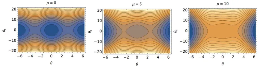
FIG. 2. The filament-bundle elasticaθs−θphase space, Eq. (3.10), forP=0,Q=21,γ=0 and an increasing sliding resistance µ, as indicated. The classical, periodic elastica is recovered forµ=0=γ.
defined as the horizontal distance between the actuation point of the post-buckled configuration,xd, and its undeformed reference position,x0d=1. In the absence of external forces, or for force magnitudes that are smaller than the critical load,Q<Qc, the filament-bundle cannot buckle and remains straight.
The filament-bundle elastica equation Eq.(3.5) can be integrated to give
θ2
s −θs2(0) =2Q(cosθ−cosθ0) +µ(θ−θ0)2−
2γ
1−γθs(0)(θ−θ0), (3.10) where we have consideredP=0 and Q=21, and free torque condition at both ends for simplicity. Eq. (3.10) definesθs−θ filament-bundle phase-space. The singular points are given byθs∗=0 and
Qsinθ∗=µ(θ∗−θ0). Whenµ>Q, the only singular point is the origin of the phase-space, forθ0=0.
Fig. 2 shows how the the cross-linking mechanics induces a gradual lost of periodicity in the phase-space asµ increases. Symmetric, periodic solution captured by elliptic functions, Eq. (2.3), are not possible for the filament-bundle elastica. This is in contrast with the periodic singular points for the classical case that spans through the phase-space (Fig. 2,µ=0), similar to the pendulum portrait. Interestingly, θ0induces a shift of the singular point given byθ∗=−µθ0/(Q−µ), to the linear level, and brakes the
usual Euler-elastica symmetry. Linear analysis shows that no buckling may occur ifQ<µ.
4. The filament-Bundle elastica at immediate postbuckling
We consider a bundle elastica subjected to a generalised external load given by Eq. (3.5). The basal angle is clamped base,θ(0) =0, and the distal end is hinged,θs(1) =0. However, the bundle is constrained to move along the horizontal axis, Eq. (3.9). The resulting BVP reads
θss+γ µ
Z 1
0 (θ(
s′)−θ0)ds′−µ(θ−θ0) +Qsinθ+Pcosθ=0, (4.1)
xs=cosθ, (4.2)
ys=sinθ, (4.3)
[image:7.612.84.500.158.265.2]post-buckling,θ,Q,Pare very small, and may be expanded according to the perturbation parameterε<<1, θ(s) =εθ0(s) +ε3θ1(s) (4.4)
Q=q0+ε2q1, (4.5)
P=εp0+ε3p1, (4.6)
(4.7) where we exploited the symmetry of the solutionθ(s)→ −θ(s), and the parity of the trigonometric functions appearing in Eq. (4.1). Perturbing Eq. (3.5), and collecting the first order terms inε, we find the reduced BVP and associated boundary conditions in terms of the perturbed variables
θ0′′+λ2θ
0+p0=0 (4.8)
θ0(0) =θ0′(1) =
Z 1
0
θ0ds=0, (4.9)
while theε3terms give
θ1′′+λ2θ
1=
1 6q0θ0
3+1
2p0θ0
2−q
1θ0−p1−γ µ
Z 1
0
1 6θ0
3ds (4.10)
θ1(0) =θ1′(1) =0=
Z 1
0
θ1−
1 6θ0
3
ds. (4.11)
whereλ2=q
0−µ. It is more convenient here to map the BVP Eqs. (4.8), (4.9) to an equivalent 3rd
order eigenvalue problem in which Eq. (4.8) can be used as an additional boundary condition. The first order solution is given by
θi
0(s) =λisin(λis) +cos(λis)−1, (4.12) where theith eigenvalue is given by the solvability condition
tanλi=λi, (4.13)
whereasp0=λ2.
We focus here on the solution of the 1st mode,i=1, and hereafter we drop thei’s and denote by λ the eigenvalue for the 1st mode. The next order approximation is obtained by substituting θ0(s)in
Eqs. (4.10), (4.11). Following [48], we change variables toζ=λs+ν, so that
θ0(ζ) =usin(ζ)−1, (4.14) u=√1+λ2andν=arctan(1/λ). Eqs. (4.10), (4.11) reduce to
θ1′′(ζ) +θ1(ζ) =− u3
24sin(3ζ)−k1sinζ−k2 (4.15) θ1(ν) =θ1′(λ+ν) =0=
Z λ+ν
ν
θ1−
1 6θ0
3
dζ. (4.16)
where primes now denote derivatives inζ and the new parametersk1,k2are defined by k1=
q1u
λ2 − u3
8 +
u
2 (4.17)
k2= 1
λ2
p1−q1+γ µ
Z λ+ν
ν
1 6θ0
3dζ
−1
The sine contribution of the homogeneous solution is already accounted for in Eq. (4.14), and the general solution of Eq. (4.15) is
θ1(ζ) =acos(ξ) +
1 192u
3sin(3ξ) +1
2k1ξcos(ξ)−k2, (4.19) where the three unknownsa,k1andk2are determined by the boundary conditions in Eq.(4.16). This
givesa=k1(λ+ν)/2, k2=
u
2λ
u2
32cos(3v)−
u2
4 cos(v) +
u
4sin(2v)−cosv
+u
2
4 + 1
6, (4.20)
k1= u3
96λ sin(3v)sec(v)− 2k2
λ sec(v). (4.21)
Onceλ is known, the constantsk1,k2can be evaluated from above, whereasq1,p1are extracted from
Eqs. (4.17) and (4.18) directly, withq0=λ2+µ,p0=λ2.
The first root of the solvability condition Eq. (4.13) isλ2=20.1907. For the first mode, k
1=
−1.15083 and k2=2.83411. The buckling and transversal loads are modified by the cross-linking
mechanics via
Q=20.1907+µ+38.3389ε2,
(4.22)
P=20.1907ε+ (102.2920+12.6007γ µ)ε3. (4.23)
The Euler-elastica results are recovered in absence of the interfilament coupling,µ=γ=0. This can be used to describe the bifurcation curves analytically, immediately after buckling. The curvature at
s=0 and the displacement of the actuation point are common observables during force-discplacement experiments. The curvatureθs(0)can be evaluated from Eqs. (4.14) and (4.19),
θs(0) =εθ0s(0) +ε3θ1s(0) =20.19072ε+0.37565ε3, (4.24) Bothθ0(s)andθ1(s)are onlyλ-dependent, thus the deformed shape at immediate post-buckling
is identical to the classical Euler-elastica. However, buckling occur at different loading, given by the dependence on the perturbation parameterε. Nevertheless, the bifurcation diagram is also modified due to the bundle load-response in Eqs. (4.22), (4.23). The total displacement of the actuation point is given by the moment balance at the base
δ=1−x(1) =1−1P
θs(0) + (1−γ)µ
Z 1
0
θds′
. (4.25)
This can be further simplified by using Eq. (4.8), δ=ε
2(8.08814+0.222548µ+0.777452γ µ)
1.60235+ε2(8.11795+γ µ) . (4.26)
5. Geometrically exact numerical solutions
Here, we numerically solve the geometrically exact deformations for a filament-bundle elastica, de-scribed by the boundary value problem in Eq. (3.5). We consider two different loading conditions, as discussed bellow. We follow the numerical scheme presented in Gadˆelha et al. [19] that employs the continuation method for BVP systems [48, 49, 50, 18].
5.1 Simply supported filament-bundle elastica: the pitchfork buckling bifurcation
We start by investigating filament-bundle configurations for symmetric, torque-free conditions at both ends. Fig. 3 depicts filament-bundle deformations for the first three shape modes, for an increasing loadingQfor and a small sliding resistance coefficientµ=5, for bothγ =0 (red) andγ=1 (blue). A clear distinction betweenγ=0 andγ=1 can be observed. Forγ=1 the bundle shapes differ very weakly from the classical elastica, as most of the blue shapes are almost exactly overlaid by the Euler-elastica, apart from the last three loading conditions for the first mode (first column, 5th-7th rows in Fig. 3). The observed shape symmetry is an expected feature of homogeneous filament-bundles, due to the even distribution of sliding resistance. In contrast, as the basal sliding resistance increases, and thusγdecreases, the cross-linking moments act unevenly along the bundle, and asymmetrical shapes are induced; compare blue and red curves for the 1st mode in Fig. 3 (first column). Opposing moments are concentrated towards the basal end, as the constituent filaments are prevented to slide at this point. This causes counter-bends near the base, characterised by deformations in opposition to the principal bend. This is clearly depicted for the first mode in Fig. 3 forδ=1, when the actuation point meets the basal end (red curve at the first column and 5th row in Fig. 3). The formed loop (red curve) is asymmetric and slightly rotated relative to the symmetrical Euler-elastica elliptical curve (black/blue curves, first column, 5th row).
Forδ >1 (6th and 7th rows in Fig. 3), the loop is attracted towards the basal end, instead of re-maining at the centre. Even though the boundary conditions are symmetric (free torque condition at both ends), the basal interfilament resistance introduces an intrinsic asymmetry in the bundle system. For higher modes, the lemniscate of Bernoulli, observed whenδ =1 (5th row), is described by elliptic functions, characterised by its periodicity and symmetry. However, the periodicity is lost whenγ<1 andµ>0, as depicted in Fig. 2. For an odd number of loops whenδ >1, we observe an asymmetrical distribution of loops towards one end for the red curves, which can be either the proximal or the distal boundary depending on the mode (compare the red curves of the first and third modes in Fig. 3). Sym-metric distribution of loops is regained for even modes, see red curve for the second mode in Fig. 3, though they appear to be closer to the end points (red curve) when compared with homogeneous bundles (blue curves).
FIG. 3. Geometrically exact deformations of a simply supported filament-bundle elastica for the first three modes and 06δ61.6, defined in Eq. (3.9). The basal end (white marker) is held fixed while the position of the distal end (black marker) is gradually changed for an increasingδ, from top row (δ=0) to bottom (δ=1.6). For a given shape, the distal end (black marker) moves towards the basal point (white marker), until eventually they meet (δ=1, 5th row). From this point, the black marker continues the movement in the same direction, thus gradually increasing the distance between the end poins (δ>1, 6th and 7th rows). Columns, left to right, depict the first, second and third modes, respectively. Black curves show the classical Euler-elastica solutions. Note that blue and black curves are overlaid for higher modes (2nd and 3rd columns). For clarity, red curves depicting filament-bundle solutions forµ=5 andγ=0 are mirrored in respect to the origin, thus they appear reflected relative to the black/blue curves.
for filament-bundles [19].
5.2 Clamped-pinned filament-bundle, violent jumps and hysteresis
Elastica solutions are known to be highly sensitive to boundary conditions [18]. In contrast to the sym-metric free-torque system, the buckling instability of a filament-bundle with one end clamped and the other end pinned is remarkably distinct. Figs. 5 and 6 compares the static configurations for increasing values ofµand two values ofγ. When the bundle is homogeneous,γ=1 in Fig. 6, the post-buckled con-figurations are very similar to the Euler-elastica case, as also observed in Fig. 3. For a non-homogeneous bundle,γ=0 in Fig. 5, the static configurations undergo a transition for large values ofµso that when δ>1, the post-buckled shapes resembles the ones in Fig. 3 for the first mode (1st column). Immediately close to the buckling bifurcation, all cases in Figs. 5 and 6 resemble the classical elastica, as predicted from the weakly non-linear analysis, as Eqs. (4.12), (4.19) are independent ofλ.
elas-FIG. 4. The filament-bundle pitchfork bifurcation for the first three modes associated with Fig. 3 for 06δ61.6. The critical load is depicted by the colored markers, calculated from linear perturbation analysis of Eq. (3.5).
tica. Negative slopes correspond to a negative work for a positive displacement incrementδ. This entails that static configurations, depicted in red in Fig. 7(a), and corresponding red markers at theQ−δ curve, are statically unstable. In other words, for given displacementδ the elastica shape is unique, however, for a given external loadQ, multiple solutions are possible, up to a maximum of four different static states. IfQvaries, a stable static configuration may violently jump to the next stable state, given suitable disturbances, equivalent to transitions between the blue curves in the bifurcation diagram in Fig. 7(a). Hysteresis loop is therefore possible. TheP−δ curve also varies non-monotonically, however, it does not have the same impact on the stability of the static configurations, asPdoes not contribute to the work done on the elastica.
The bifurcation landscape of the filament-bundle elastica is very distinct from the classical case. Whenγ=0, theQ−δ curve in Fig. 7(b) displays a monotonic behaviour instead. In this case, all static states are both stable and unique. Thus, for a given loadQ, the displacementδ is uniquely determined, and vice-versa. In this regime, the cross-linking mechanics has an stabilizing effect and suppresses the occurrence of multiple states and hysteresis whenµis increased in Fig. 8 forγ=0. Interestingly,P
reduces to a negligible magnitude in Fig. 7(b). The bundle elastica undergoes dramatic shape change characterised by a loop formation for δ >1 (Fig. 7(b) and 5), similar to the symmetric free-torque elastica in Fig. 3. On the other hand, homogeneous bundles (γ=1) behave very similarly to an Euler-elastica, compare Figs. 7(c) and 7(a). The bifurcation diagram is self-similar forγ=1, see Fig. 8 for three values ofµ. The homogeneous bundle elastica thus behaves as the classical elastica, however, characterized by a higher resultant bending stiffness. In this case, the interfilament resistance reinforce the effective stiffness of bundle structure. The cross-linking mechanics weakly stabilises on the inherit the unstable states, characterised by the negative slope of theQ−δ curve, as a gentle reduction of the negative gradient is observed in Fig. 9(b), although the work done on the bundle approaches zero in this region. In this case, multiple states, non-uniqueness, violent jumps and hysteresis are equally manifested in homogeneous filament-bundles (γ=1).
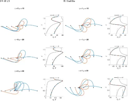
FIG. 5. Clamped-pinned filament bundle elastica for increasing values ofµandγ=0. Blue to red curves track different actuation displacementδ.
FIG. 6. Clamped-pinned filament bundle elastica for increasing values ofµandγ=1. Blue to red curves track different actuation displacementδ.
to buckle in both directions (Fig. 4). If we introduce the external torquem0ats=0 as a new bifurcation
parameter, the pitchfork bifurcation (Fig. 4) unfolds in the three-dimensional space asm0is increased,
FIG. 7. Bifurcation diagram for a filament-bundle elastica and associated static configurations. The critical loadQcis given by the starting value ofQat the bifurcation diagram, depicted by the blue circles whenδ=0, calculated from the linear analysis. Red (blue) markers and associated static configuration are unstable (stable) states. Dashed black and gray curves are the bifurcation curves derived from the weakly non-linear analysis.
4 and 7(a) are thus the planar cross-section of the 3D bifurcation surface, where the imposed angle θ(0) =0 can be achieved by enforcing a suitable external moment m0 for this constraint, thus the
equivalence between both torque-free and clamped-pinned cases for an elastica. The observed snapping and hysteresis in Fig. 7(a) originate from a saddle-node bifurcation, which itself is induced by unfolding the pitchfork bifurcation in Fig. 4 [49, 50]. The projection on them0−Qplane is thus characterized
by a cusp catastrophe [50]. Each divergent curve originating from the cusp at a criticalm∗0tracks the position of the saddle-node points asm0increases [50, 18].
FIG. 8. Filament bundle shape and Bifurcation diagram for basal complianceγ=0,1 and varying sliding filament resistance. Blue (red) shapes depict stable (unstable) configurations for a varying loading case.
disappear for µ >35 (Fig. 8). Likewise, unstable configurations are modified by µ (Fig. 5), while buckled deformations for largeQhave their stability modified. This is depicted in the transition from Fig. 8 forµ=0 to Fig. 7(b) forµ=40, or equally in Fig. 9 (a). The non-homogeneous bundles (γ<1) generate internal moments near the base in opposition to the imposed curvature (see the first mode in Fig. 3, red curve). This induces, via Eq. 3.4,θ(0)to change its orientation via the sliding displacement, which is in turn curvature-dependent. The emergence of counter-basal orientation is thus a manifestation of the counterbend phenomenon in filament-bundles [19, 7].
The basal counter-curvature increases withµ. Consequently, the external torquem0required for the
θ(0) =0 constraint is gradually reduced.Pis equally reduced in magnitude, as the basal counterbend formation, for largeµ, is sufficient to hold the endpoint orientation parallel to thex-axis, see Fig. 7(b). When µ>35, the external momentm0 reduces significantly, and the saddle nodes points disappear
(Figs. 9, 7(b) and 8). The clamped-pinned bundle elastica thus returns to the pitchfork buckling insta-bility characteristic of symmetric boundary conditions (Fig. 4). Increasingµthus move the system to a stable cross-section of the 4D(δ,Q,µ,m0)-bifurcation diagram, or equivalently in the 3D space in Fig.
[image:15.612.87.499.137.464.2]FIG. 9. The imperfection-sensitivity diagram in the (δ,Q,µ)-space for bothγ=0,1, and associated projections in theδ−Q
plane. (a) depicts the folding of the saddle-node bifurcation back to the pitchfork bifurcation asµincreases. Hysteresis and violent jumps are only possible forµ<35. (b) shows the expansion of the self-similarδ−Qbifurcation curves, characterised by hysteresis and violent jumps for any value ofµ.
asµincreases (Fig. 9(a)). The cross-linking mechanics is able reduce the external torquem0necessary
to enforce the clamped constraint below the criticalm∗0required for the bifurcation to unfold from the pitchfork bifurcation basin [18, 50, 49, 39]. This non-trivial folding of the bifurcation surface (Fig. 9), in the reversed direction, as the external torquem0is lowered whenµis augumented, is thus a genuine
manifestation of the non-local coupling between boundary and interior points of the filament-bundle elastica via the non-local cross-linking moments. The clamped base is therefore a natural condition for non-homogeneous bundles (γ<1).
We finish this section by contrasting the perturbation approximations Eqs. (4.4), (4.12)-(4.26) with numerical solutions in Fig. 10 at immediate post-buckling forγ=0 andµ=0,5,10. A good agreement is observed, even for the deformations beyond the immediate post-buckling approximation. The accu-racy of the asymptotic solution gradually decreases with the sliding resistanceµ. The dashed lines in the bifurcation diagrams, Figs. 7 and 8, are taken from Eqs. (4.22)-(4.26), which again shows a good agreement forµ<10. The pertubative solution captures accurately the buckling load required for bifur-cation, as expected from the linear theory for bothγ=0,1 in Figs. 7 and 8. Predictions of the restoring loadPare accurate even for high values ofµ, see the dashed grayδ−Pcurves in Fig. 8. Therefore,
Premains within theε3validity. Asµincreases, theδ−Qblack curves deviates from the analytical
solution, increasingly more forγ=1. This can be understood from Eqs. (4.22), (4.23) and (4.26). The basal compliance only contributes to higher-order corrections, and only influencesθ1approximation via
FIG. 10. Comparison between numerical solutions (black curves) and the analytical approximations (dashed curves) for the Euler-elastica case (a) and a filament-bundle withµ=5 (b) andµ=10 (c), both forγ=0.
loadQ∗instead, and by considering the next power inε for theQ,Pandθ expansions in Eqs. (4.4)-(4.6). This is at the expense of a more convoluted perturbative analysis, and thus beyond the purpose of this paper.
6. Conclusions
The richness of families of Euler elastica shapes have captivated our fascination for centuries [47]. While the buckling phenomena share properties with other dynamical systems, such as the movement of a pen-dulum, the boundary value constraints lead to an ever rich instability behaviour, highly dependent on boundary conditions and imperfections of the system [18, 49, 50, 39]. We focused our investigation on the static configurations of filament-bundles composed by individual elastica rods, cross-linked with elastic connectors[14, 43]. The resulting filament-bundle elastica system is augmented by internal mo-ments arising from the cross-linking mechanics along the bundle, modifying boundary value properties non-locally. This in turn triggers symmetry-breaking and modifies the buckling instability bifurcation landscape.
For simply supported filament-bundles, free from external moments at both ends, the static config-urations in Fig. 3 (for small displacements) and the pitchfork bifurcation structure in Fig. 4 are remi-niscent of Euler-elastica buckling. These similarities are deceptive while performing force-displacement experiments, as filament-bundle systems could be easily mistaken by an Euler-Bernoulli rod, see Fig. 1(a). These similarities may have been the reason why it took over than 30 years, since the first buckling ex-periments with naturally occurring cross-linking bundles, as found in sperm flagellum [16, 17, 15, 10, 9] to unveil large cross-linking deformations, with the discovery of the counterbend phenomenon [7, 8] (Fig. 1 (b,c)). Instead, filament-bundles were considered to behave as an assembly of elastica rods with an effectively higher stiffness proportional to the number of constituent filaments [16, 17, 15, 10, 9]. Indeed, the basal counterbend predicted here (Fig. 3, red curve, 1st column), is characterised by small deformations at the base that would be challenging to capture during flagellar bucking experiments un-der a microscope. Furthermore, despite the fact that homogeneous bundles (γ=1) behave very similarly to an elastica rod, Figs. 3 and 6, the interfilament resistance increases the effective stiffness beyond the combined bending stiffness of each constituent filament, as shown in Fig. (4). Subject to boundary conditions, the buckling load can either depend on both basal compliance and sliding resistance, as in Fig. (4), or just depend onµ, see Eq. (4.22).
ex-ternal moments are absent) in a higher dimension. In this case, the imperfection-sensitivity space [50] is augmented by the external torque bifurcation parameter. The Filament-bundle elastica modifies the bifurcation landscape via a bimodal response (Fig. 9). This is triggered by the non-local coupling between internal and boundary moments via the cross-linking mechanics [19, 38]. Homogeneous bun-dles (γ=1) conserve the structural saddle-node bifurcation present in classical elastica systems, and display a self-similar, dilating, but conserved, pitchfork unfolding asµ increases. This is shown by theδ−Qcross-sections of the(δ,Q,µ)-bifurcation space in Figs. 8 and 9(b). On the other had, non-homogeneous bundles, with interfilament sliding prevented at the base, gradually folds the saddle-node bifurcation back to the original pitchfork bifurcation (Fig. 9(a)), only present in simply supported elastica systems (Fig. 4). This leads to the emergence of a new reversed cusp catastrophe, in which saddle-nodes eventually collide and disappear beyond the cusp point for a criticalµ∗at theQ−µ
pro-jection of the bifurcation space Fig. 9(a). This is despite the fact that a destabilising external moment constrains the orientation of the proximal end. As a result, whenµ>µ∗, hysteresis and violent jumps are not present in the system, and the bundle elastica shape resembles the ones obtained for the free torque condition in Fig. 3. The non-local boundary moments present in filament-bundles effectively merges two distinct elastica behaviours that can only be triggered by different boundary constraints: the simply supported and the clamped-pinned cases. The resultant bifurcation landscape of the filament bundle elastica is however far more complicated, as there must exist some form of cusp catastrophe cusp continuously linking the bimodal behaviour asγ varies, in the augmented fourth-dimensional bifurca-tion space (δ,Q,µ,γ). However, more work is needed to elucidate the bifurcation landscape embedded in this higher dimensional space, and associated multi-configuration stability analysis.
The stabilising effect of the reversed cusp catastrophe for non-homogeneous bundles is a genuine manifestation of the counterbend phenomenon [19]. Counterbends concentrated towards the basal end reduces (Figs. 3 and 7) the magnitude of destabilising external torques required to hold the basal orienta-tion during buckling. Basal conterbending is a natural deformaorienta-tion mode for clamped filament-bundles. Indeed, flagella and cilia found in nature are cemented to a basal body or connecting piece [13, 12]. This basal body biological adaptation is thus extremely advantageous for flagellates, given that non-local control of the bundle can be achieved by tuning the basal compliance. Under mechanical stress, for instance, increased contraction of the basal body may modify the stability of the bucking phenom-ena, from violent jumps and snapping after buckling, to smooth transitions for a varying external load. This evolutionary adaptation may be relevant in systems where the buckling phenomena is prevalent [42, 51, 40], as violent jumps may lead to structural damage and even fracture. Likewise, bimodal tunning via basal compliance control may influence the sensitivity to hysteresis of the bundle, and thus impact the flagellar wave generation during molecular-motor self-organisation [52, 38, 29, 53, 54, 21].
7. Acknowledgements
References
[1] C. Heussinger, M. Bathe, and E. Frey. Statistical mechanics of semiflexible bundles of wormlike polymer chains.Physical Review Letters, 99(4):048101, July 2007.
[2] Claus Heussinger, Felix Sch¨uller, and Erwin Frey. Statics and dynamics of the wormlike bundle model.Phys. Rev. E, 81(2):021904, Feb 2010.
[3] A. Hilfinger and F. J¨ulicher. The chirality of ciliary beats. Phys. Biol., 5:016003–016015, 2008. [4] M. A. E. Claessens, M. Bathe, E. Frey, and A. R. Bausch. Actin-binding proteins sensitively
mediate f-actin bundle stiffness.Nature Materials, 5(9):748–753, August 2006.
[5] J.A. Tolomeo and M.C. Holley. Mechanics of microtubule bundles in pillar cells from the inner ear.Biophysical Journal, 73(4):2241–2247, October 1997.
[6] M. Bathe, C. Heussinger, M.A.E. Claessens, A. R. Bausch, and E. Frey. Cytoskeletal bundle mechanics.Biophysical Journal, 94(8):2955–2964, April 2008.
[7] Dominic W Pelle, Charles J Brokaw, Kathleen A Lesich, and Charles B Lindemann. Mechanical properties of the passive sea urchin sperm flagellum.Cell Motil Cytoskeleton, 66(9):721–735, Sep 2009.
[8] Charles B. Lindemann, Lisa J. Macauley, and Kathleen A. Lesich. The counterbend phenomenon in dynein-disabled rat sperm flagella and what it reveals about the interdoublet elasticity. Biophys-ical Journal, 89(2):1165 –1174, 2005.
[9] M. Okuno and Y. Hiramoto. Direct measurements of the stiffness of echinoderm sperm flagella.
Journal of Experimental Biology, 79(1):235, 1979.
[10] M. Okuno. Inhibition and relaxation of sea urchin sperm flagella by vanadate.The Journal of Cell Biology, 85(3):712, 1980.
[11] B. Afzelius. Electron microscopy of the sperm tail.Biophys. Cytol., 5:269, 1959.
[12] Don W. Fawcett, William Bloom, and Elio Raviola. A Textbook of Histology. Chapman & Hall, June 1994.
[13] P. Satir. Studies on cilia: Ii examination of the distal region of the ciliary shaft and the role of the filaments in motility.J. Cell Biol., 26(3):805, 1965.
[14] C. J. Brokaw. Bend propagation by a sliding filament model for flagella. J. Exp. Biol., 55(2):289– 304, 1971.
[15] C. B. Lindemann, W. G. Rudd, and R. Rikmenspoel. The stiffness of the flagella of impaled bull sperm.Biophysical Journal, 13(5):437–448, May 1973.
[16] B. Alberts.Molecular Biology of the Cell. Garland Science, New York, 2002.
[18] SS Antman. Nonlinear Problems of Elasticity, volume 107 ofApplied Mathematical Sciences. Springer, 2005.
[19] H. Gadˆelha, E. A. Gaffney, and A. Goriely. The counterbend phenomenon in flagellar axonemes and cross-linked filament bundles.Proceedings of the National Academy of Sciences, July 2013. [20] Gang Xu, Kate S Wilson, Ruth J Okamoto, Jin-Yu Shao, Susan K Dutcher, and Philip V Bayly.
Flexural rigidity and shear stiffness of flagella estimated from induced bends and counterbends.
Biophysical Journal, 110(12):2759–2768, 2016.
[21] E. A. Gaffney, H. Gadˆelha, D. J. Smith, J.R. Blake, and J. C. Kirkman-Brown. Mammalian sperm motility: Observation and theory.Annual Review of Fluid Mechanics, 2011.
[22] Philip V. Bayly and Kate S. Wilson. Equations of Interdoublet Separation during Flagella Motion Reveal Mechanisms of Wave Propagation and Instability.Biophysical Journal, 107(7):1756–1772, October 2014.
[23] P. V. Bayly and K. S. Wilson. Analysis of unstable modes distinguishes mathematical models of flagellar motion.Journal of The Royal Society Interface, 12(106):20150124, May 2015.
[24] Charles J. Brokaw. Flagellar Movement: A Sliding Filament Model.Science, 178(4060):455–462, November 1972.
[25] Charles J. Brokaw. Computer simulation of flagellar movement. vi. simple curvature-controlled models are incompletely specified.J. Biophys., 48:633, 1985.
[26] S´ebastien Camalet, Frank J¨ulicher, and Jacques Prost. Self-organized beating and swimming of internally driven filaments.Phys. Rev. Lett., 82:1590, 1999.
[27] M Hines and JJ Blum. Bend propagation in flagella. ii. incorporation of dynein cross-bridge kinetics into the equations of motion. Biophysical journal, 25(3):421, 1979.
[28] Charles B Lindemann. A” geometric clutch” hypothesis to explain oscillations of the axoneme of cilia and flagella.Journal of theoretical biology, 168(2):175–189, 1994.
[29] Ingmar H. Riedel-Kruse, Andreas Hilfinger, Jonathon Howard, and Frank J¨ulicher. How molecular motors shape the flagellar beat. HFSP Journal, 1(3):192–208, 2007.
[30] Pablo Sartori, Veikko F. Geyer, Andre Scholich, Frank J¨ulicher, and Jonathon Howard. Dynamic curvature regulation accounts for the symmetric and asymmetric beats of Chlamydomonas flagella.
eLife, 5:e13258, May 2016.
[31] Charles J. Brokaw. Molecular mechanism for oscillation in flagella and muscle.Proc. Natl Acad. Sci., 72:3102, 1975.
[32] Charles J Brokaw. Computer simulation of flagellar movement x: doublet pair splitting and bend propagation modeled using stochastic dynein kinetics.Cytoskeleton, 71(4):273–284, 2014. [33] Charles B Lindemann and Kathleen A Lesich. Flagellar and ciliary beating: the proven and the
[34] M. Hines and JJ. Blum. Bend propagation in flagella. i. derivation of equations of motion and their simulation.J. Biophys., 23:41, 1978.
[35] Robert Rikmenspoel. Contractile mechanisms in flagella.Biophysical journal, 11(5):446, 1971. [36] Charles J Brokaw. Computer simulation of flagellar movement ix. oscillation and symmetry
break-ing in a model for short flagella and nodal cilia. Cell motility and the cytoskeleton, 60(1):35–47, 2005.
[37] C.J. Brokaw and D.R. Rintala. Computer simulation of flagellar movement. iii. models incorpo-rating cross-bridge kinetics.J. Mechanochem. Cell. Motil., 3(2):77, 1975.
[38] Rachel Coy and Hermes Gadˆelha. The counterbend dynamics of cross-linked filament bundles and flagella.Journal of The Royal Society Interface, 14(130):20170065, 2017.
[39] E Christopher Zeeman. Catastrophe theory.Scientific American, 234(4):65–83, 1976.
[40] L. E. Becker and M. J. Shelley. Instability of elastic filaments in shear flow yields first-normal-stress differences.Phys. Rev. Lett., 87:198301–198304, 2001.
[41] M. Kurachi, M. Hoshi, and H. Tashiro. Buckling of a single microtubule by optical trapping forces: Direct measurement of microtubule rigidity. Cell Motility and the Cytoskeleton, 30(3):221–228, January 1995.
[42] Gabriele De Canio, Eric Lauga, and Raymond E Goldstein. Spontaneous oscillations of elastic fil-aments induced by molecular motors.Journal of The Royal Society Interface, 14(136):20170491, 2017.
[43] R. Everaers, R. Bundschuh, and K. Kremer. Fluctuations and stiffness of double-stranded poly-mers: railway-track model.EPL (Europhysics Letters), 29:263, 1995.
[44] Y. C. Fung and P. Tong. Classical and computational solid mechanics. Word Scientific, 2001. [45] L D Landau, L. P. Pitaevskii, E.M. Lifshitz, and A. M. Kosevich.Theory of Elasticity.
Butterworth-Heinemann, 3rd edition, January 1986.
[46] S.P. Timoshenko and J.M. Gere.Theory of elastic stability. McGraw-Hill, New York, 1961. [47] L. Euler. Methodus inveniendi lineas curvas maximi minimive proprietate gaudentes, sive solutio
problematis isoperimetrici lattissimo sensu accepti. chapter Additamentum 1, eulerarchive.org E065, 1744.
[48] CY Wang. Post-buckling of a clamped-simply supported elastica. International Journal of Non-Linear Mechanics, 32(6):1115–1122, 1997.
[49] E. C. Zeeman. Euler buckling, pages 373–395. Springer Berlin Heidelberg, Berlin, Heidelberg, 1976.
[51] L. Bourdieu, T. Duke, M. B. Elowitz, D. A. Winkelmann, S. Leibler, and A. Libchaber. Spiral defects in motility assays: A measure of motor protein force.Phys. Rev. Lett., 75:176–179, 1995. [52] David Oriola, Hermes Gadˆelha, and Jaume Casademunt. Nonlinear amplitude dynamics in
flagel-lar beating. Royal Society Open Science, 4(3):160698, 2017.
[53] C. J. Brokaw. Thinking about flagellar oscillations.Cell. Mot. Cytoskel., 66(8):425–436, 2009. [54] C. J. Brokaw. Computer simulation of flagellar movement VIII: coordination of dynein by