Int. J. Electrochem. Sci., 6 (2011) 1159 - 1174
International Journal of
ELECTROCHEMICAL
SCIENCE
www.electrochemsci.org
Study of Influence of Electrode Geometry on Impedance
Spectroscopy
Riaz Ahmed1,* Ken Reifsnider2 1
Dept. of Mechanical Engineering, Khulna University of Engineering & Technology, Khulna – 920300, Bangladesh,
2
University of South Carolina, Columbia, SC 29208, USA *
E-mail: [email protected]
Received: 28 November 2010 / Accepted: 18 December 2010 / Published: 1 April 2011
Electrochemical Impedance Spectroscopy (EIS) is a powerful and proven tool for analyzing AC impedance response. A conventional three electrode EIS method was used to perform the investigation in the present study. Saturated potassium chloride solution was used as the electrolyte and three different material rods were used as working electrodes. Different configurations of electrode area were exposed to the electrolyte as an active area to investigate electrode geometry effects. Counter to working electrode distance was also altered while keeping the working electrode effective area constant to explore the AC response dependence on the variation of ion travel distance. Some controlled experiments were done to validate the experimental setup and to provide a control condition for comparison with experimental results. A frequency range of 100 mHz to 1 MHz was used for all experiments. In our analysis, we have found a noteworthy influence of electrode geometry on AC impedance response. For all electrodes, impedance decreases with the increase of effective area of the electrolyte. High frequency impedance is not as dependent on geometry as low frequency response. The observed phase shift angle drops in the high frequency region with increased working electrode area, whereas at low frequency the reverse is true. Resistance and capacitive reactance both decrease with an increase of area, but resistance response is more pronounce than reactance. For lower frequencies, small changes in working area produce very distinctive EIS variations. Electrode material as well as geometry was systematically varied in the present study. From these and other studies, we hope to develop a fundamental foundation for understanding specific changes in local geometry in fuel cell (and other) electrodes as a method of designing local morphology for specific performance.
Keywords: SOFC, electrode, geometry, EIS
1. INTRODUCTION
lower or zero emissions.[1,2] Current SOFC technology typically uses porous materials that have little or no ionic conduction for the electrodes. In particular, porous LaMnO3 is commonly used as the
cathode material. Because LaMnO3 is largely an electronic-only conductor, high porosity is critical for
increasing the number of active regions for oxygen reduction in the electrochemical conversion. The geometry and dimensions of SOFCs can affect the performance of the fuel cell. However, effects due to changes to the design of the SOFCs can be complicated, requiring trial and error to improve the fuel cell. In particular, the specific effects of changing the thickness of the cathode for fuel cell performance can be difficult to determine[3].
Solid oxide fuel cell (SOFC) systems for aircraft applications require an order of magnitude increase in specific power density (1.0kWkg−1) and long life. While significant research is underway to develop anode supported cells which operate at temperatures in the range of 650–800 ◦C, concerns about Cr-contamination from the metal interconnect may drive the operating temperature down further, to 750 ◦C and lower. Higher temperatures, 850–1000 ◦C, are more favorable in order to achieve specific power densities of 1.0kWkg−1. Since metal interconnects are not practical at these high temperatures and can account for up to 75% of the weight of the stack, NASA is pursuing a design that uses a thin, LaCrO3- based ceramic interconnect that incorporates gas channels into the electrodes. The bi-electrode supported cell (BSC) uses porous YSZ scaffolds, on either side of a 10–20 µm electrolyte. The key feature of the design concept is the symmetrical cell, which is made by supporting the thin electrolyte on both sides with a porous YSZ support structure, thus the name bi-supported cell or BSC[4]. In our present study, we are focusing on BSC concept and figure 1 showing such electrolyte supported structure.
Generally, the cathode and anode of a fuel cell are made of porous materials. Figure 2 shows the porous anode and cathode of a BSC structure. Porous materials play two key roles in fuel cell technology. The first is that of transporting gases to/from the fuel cell electrodes. [5].
Figure 2. Porous anode and cathode of a BSC structure[4].
The second vital role of porous materials is their electrochemical function as an anode or cathode. In both PEMFCs and SOFCs, the electrodes play a vital role in minimizing losses attributable to electrode kinetics, and in some cases mass transport. This is achieved by maximizing the length of the so-called triple phase or three-phase boundary (TPB), a term describing the conjunction of a pore space, an ionically conducting phase, and an electronically conducting phase. In practice this is achieved by the use of porous composite electrode structures containing both ionically and electronically conducting materials[5].
The importance of local morphology has been recognized in recent years because of its large influence on fuel cell performance. Numerous papers have been published that discuss local geometry effects on half-cell performance by different Investigators. However, of the papers that do investigate the effect of cell geometry on the reliability of the determination of electrochemical parameters[6,7],
only some[8-10] provide experimental data to validate the conclusions reached by mathematical modeling. A change of morphology of the cathode with time (decreasing three phase contact area and limiting gas diffusion) and interfacial reactions between the cathode and electrolyte during operation can limit the life of SOFCs and must be minimized[11]. However, these and other discussions address morphology only in terms of bulk properties, such as particle size, particle neck size, tortuosity, porosity, and total triple phase boundary length.[12,13] Modern nano-manufacturing methods have given us the option of designing the specific local geometry for optimum performance, but the fundamental understanding, knowledge, and analytical models to specify such local details in multifunctional materials is not in the literature.
morphology. To isolate those details, we tried to observe changes in impedance response caused by altering the active area and geometry of the cathode.
In this study, we were only concentrated on changing only one geometry parameter at a time that can influence the cell performance (such as Cathode Active Area, Ion Traveling Distance etc.). To eliminate other parameters (Chemical Reaction, Poisoning, Current Density etc.) that may influence cell performance, a very high conductive aqueous solution was used as the electrolyte. We also conducted a set of cyclic voltammetry tests to confirm that the oxidation/chemical reaction was negligible in our EIS experiments.
2. EXPERIMENTAL TECHNIQUE
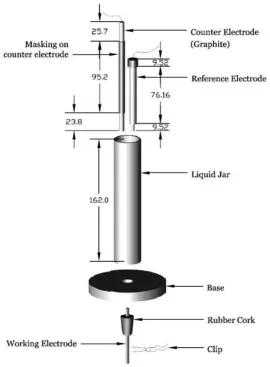
[image:4.596.164.434.354.721.2]A conventional three-electrode method was used for experimental investigations. Three different materials (copper, brass and aluminum) were used as working electrodes. Copper and brass are high-conductivity electrical conductors compared to Aluminum.
Electrode materials were rod shaped and 3 mm in diameter. Graphite rod was used as counter electrodes and saturated KCl solution served as the electrolyte. A Luggin capillary with saturated KCl solution was used as a reference electrode. For some experiments, to validate experimental setup and for establishing some controlled results, alumina was used as a working electrode with KCl solution as the electrolyte and in other setup, Deionized (DI) water was used as the electrolyte with brass/copper as the working electrode. A Faraday cage was used throughout the experimental sessions to isolate the outcomes from electromagnetic radiation and noise. An REF600 potentiostat was used from Gamry Instrument Corp. for both EIS and Cyclic Voltammetry tests.
Before using the electrode for experiments, the surface was decontaminated by Muriatic Acid and Distilled Water. A portion of the surface of the counter electrode was sealed by a rubber tube in its middle to insure that in every experiment the counter electrode active area protruding into the electrolyte remained unchanged. A small rubber cap was also used on one end (exposed side on electrolyte) of the working electrode to avoid any local singularity effect.
Approximately 120 mm electrodes were used for the experiments. One end of the electrode was exposed to the electrolyte and capped by the rubber cap, and other end was clamped with a caliper and connected to the Gamry potentiostat through an alligator clip.
The caliper was used to advance the electrode upward, which increased the active area of the working electrode exposed to the electrolyte. To maintain a constant ion travel distance for all experiments, when the working electrode exposed length was increased in the electrolyte, the counter electrode was also moved upward for the same length, except for the experiments where ion travel distance was altered deliberately while keeping working electrode area unchanged. Following every test, electrodes (working, counter and reference) and the electrolyte jar were cleaned by distilled water. A complete view of the experimental setup is shown in figure 3.
A frequency range of 100 mHz to 1 MHz was used for all tests. During the experiments, the frequency varied from an upper limit (1 MHz) to the lower limit (100 mHz). The AC potential was set at 10 mV rms and a DC potential was measured against open circuit voltage (Eoc).
3. RESULTS AND DISCUSSION
3.1. Control Results
To validate the experimental setup, two controlled experiments were done. In the first experiment, an alumina rod (ceramic) was used as the working electrode and KCl solution as the electrolyte. This is a fully capacitive system wherein alumina acts as pure insulator. In other experiments, brass and copper rods were used as working electrodes with Deionized water (DI water) as the electrolyte.
3.1.1. Alumina as working electrode
[image:6.596.152.413.171.383.2]
impedance was observed to increases linearly, as the growth of ion density was linear in the electrolyte. Since alumina is an insulator, the active area exposed to the electrolyte solution did not cause any change in the impedance response, as shown in figure-4. Also, the impedance values were very high, as expected.
Figure 4. Impedance response for alumina working electrode for varied electrode exposure areas.
3.1.2. DI water as electrolyte
Deionization is the removal of ions –positive (cation) and negative (anion) – from the water.
[image:6.596.151.447.523.732.2]
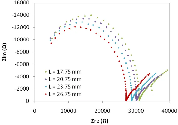
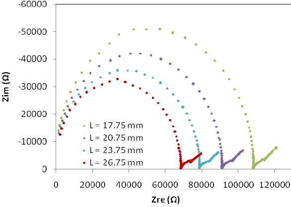
Figure 6. Nyquist plot for copper using DI water as electrolyte for varied active area.
The disadvantage of deionized water is that it is very corrosive to metal. Since DI water has no dissolved solids, water will seek equilibrium with whatever it contacts. It will react with anything it comes in contact with, especially metals and alloys like calcium, magnesium, copper, brass and stainless steel.
Four different active areas of electrode were used to observe changes in impedance response when DI water was used as the electrolyte. In Figures 5 and 6, semicircular arcs were observed from Nyquist plots, as well as 450 straight lines to the Zreal axis. These semicircles represent charge transfer resistance while the 450 lines represent Warburg impedance. Warburg Impedance is associated with diffusion. Diffusion starts at almost the same frequency for all electrode lengths (L) in the low frequency region. The DI water is an ion free liquid that attempts to bring the solution to equilibrium when it comes in contact with the metal electrode by collecting ions from the solid, after which diffusion starts. Due to the slowness of the process, diffusion occurs only in the low frequency region. We also observed that the active working electrode length alteration had a significant influence on the impedance response for this case. The influence of working electrode active area on impedance response is discussed briefly in following section.
3.2. Response due to variation of working electrode active area
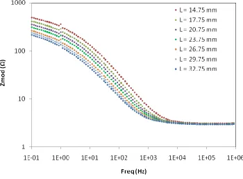
The measured impedance response for different electrode materials with the variation of active electrode area is shown in Figures 8-10. The Bode plot is segmented into two parts to provide more clarity in observing the impedance response. Figures 8 and 10 illustrate that impedance as well as resistance (the real part of impedance) and capacitive reactance (the imaginary part of impedance) decreased with an increase of active surface area of the electrode in the electrolyte.
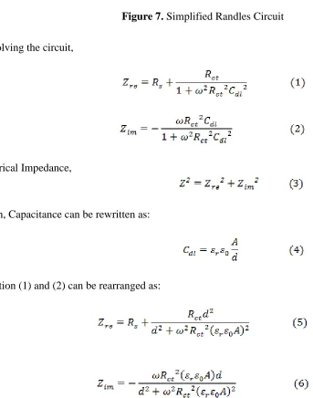
[image:8.596.76.419.315.751.2]We anticipated that our experimental setup response would follow the equivalent Randles circuit (Figure 7):
Figure 7. Simplified Randles Circuit
By solving the circuit,
Electrical Impedance,
Again, Capacitance can be rewritten as:
For our experiments, active area (A) can be calculated as: (7)
With an increase of interfacial surface area (Active area) between working electrode and electrolyte, the electrode is allowing more regions to avoid collecting charge. At high frequency, the active electrode area is fresh enough to avoid surface charges. Thus, the active surface area does not play an appreciable role and electrolyte resistance (Rs) is only responsible for impedance response.
When the oscillation frequency decreases, a very thin film of charge starts growing on the electrode-electrolyte interface with time. Owing to the formation of this film, charge transfer resistance increases with a decrease of frequency, which eventually increases impedance.
Figure 8. Magnitude of impedance response with frequency for different active area of Copper electrode
[image:9.596.127.477.296.554.2][image:10.596.123.465.393.625.2]
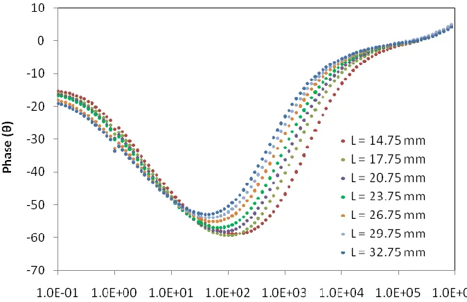
Figure 9. Phase shift variation with frequency for different active area of Copper electrode.
Figure 10. Nyquist plot for different active area of Copper electrode
region. In the intermediate frequency region, the resistance is more dominant then capacitive reactance, and in the low frequency region, it has the reverse behavior with an increase of active area. For both Copper and Brass, the minimum phase angle decreases with exposure area.
Figures 8-10 show the impedance response for the solid form of copper electrode. These experiments were also done for Brass and Aluminum electrodes as well. A hollow electrode structure of all materials was also used for the same setup and observed roughly the same phenomena for both forms of materials.
3.3. Response due to change of ion travel distance
[image:11.596.130.455.343.560.2]Keeping all other parameters unchanged, only the counter electrode was moved vertically to vary the Ion travel distance (M) for this series of experiments. Copper was used as the working electrode and the active electrode length was 14.75 mm for all tests. Initially, 64 mm was the electrode spacing. Subsequently, the counter electrode was moved upward a distance of 8 mm for each test.
Figure 11. Impedance response for varied ion travel distance.
Figure 12. Nyquist plot for varied ion travel distance.
3.4. Comparison with control results
From section-3.2 it was observed that the measured impedance parameters vary with changes of active working electrode area, which is also true for section-3.1.2 (where DI water was the electrolyte), whereas active area variation doesn’t affect the response for section-3.1.1 (alumina as a working electrode). As alumina has an absolute resistance to charge transfer, it is expected that it will show a linear variation of impedance with frequency, i.e., behave like a pure capacitor. Conversely, copper and brass are good conductors, so that active surface area is a controlling factor for those cases. At a very high frequency of excitation, due to very low charge transfer resistance, electrolyte resistance is the only active contributor and shows a flat impedance curve for good conductors, whereas for alumina, the impedance increases linearly from the very beginning because of its very high charge transfer resistance.
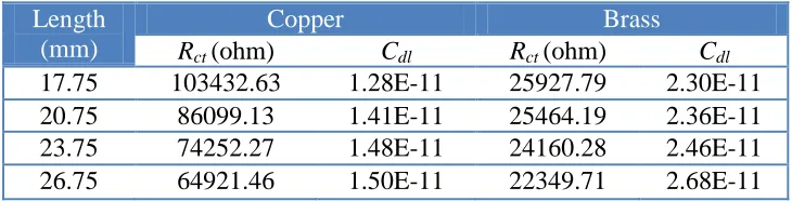
Table1. Parametric values calculated for DI water test
Length (mm)
Copper Brass
Rct(ohm) Cdl Rct(ohm) Cdl
17.75 103432.63 1.28E-11 25927.79 2.30E-11
20.75 86099.13 1.41E-11 25464.19 2.36E-11
23.75 74252.27 1.48E-11 24160.28 2.46E-11
[image:12.596.116.481.619.712.2][image:13.596.116.474.374.602.2]
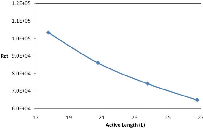
Figure 12. Charge Transfer Resistance variation with active length of Copper in DI water
Figure 13. Double Layer Capacitance variation with active length of Copper in DI water
Diffusion phenomena were observed in section 3.1.2, where deionized water was used as electrolyte, while for section 3.2 (saturated KCl as electrolyte) there was no local diffusion effect.
(Rct) and Double Layer Capacitance (Cdl) values for each setup. But for experiments, where the KCl
solution used as the electrolyte, both Rct and Cdl varies with frequency and increases with a decrease of
[image:14.596.137.454.153.365.2]frequency, due to the formation of thin charge layers, as discussed earlier.
[image:14.596.134.460.442.657.2]Figure 15. Charge Transfer Resistance variation for a range of frequency for various active length of copper.
Figure 16. Double Layer Capacitance variation for a range of frequency for various active length of copper.
Figures 15 and 16 show changes of Rct and Cdl for a small range of frequency. From Figures 15
electrode area, as discussed. Conversely, the double layer capacitance increased with active area, reflecting the formation of local charge layers with increasing area. This behavior was also true for the DI water study, as shown in Figures 12 and 13.
4. CONCLUSION
Results obtained by systematically varying the geometric factors in an electrolytic cell have been identified. Some of those results are new, and others are consistent with published observations. As shown by V. Brichzin et al.[5], impedance in this situation is generally inversely proportional to active surface area, which we observed in our results. In the high frequency region, impedance parameters were more or less insensitive to active electrode area, but highly sensitive in the low frequency region. From our controlled results, it is evident that our experimental system works well and shows pure capacitive behavior in the case of alumina working electrodes. It also demonstrated Warburg diffusion in the case of DI water. For brass and copper electrodes, little or no local diffusion was observed for saturated KCl solution electrolyte. Using the Randell’s equivalent circuit, the charge transfer resistance and double layer capacitance were found to be functions of frequency for the KCL electrolyte, , whereas for DI water these parameters were found to be roughly a fixed value. Both charge transfer resistance and double layer capacitance were found to follow a polynomial function with the alteration of active area, even for a purely capacitive system. From the literature, it is evident that charge transfer resistance shouldn’t be a function a frequency. So it is obvious that the Randles circuit model doesn’t work properly for the KCl solution case. We tried other models to fit the results and found none that work properly for the physical variables in our experiments. Of course, Randles circuit is a global approximation of system response, and is not likely to capture all of the local details under study here.
However, this work provides a foundation for understanding geometry effects on impedance response in the presence of active and passive local surfaces and with conductors and non-conductors. If a fundamental local understanding of the EIS data can be established, the present experimental method can be used not only to determine the basic nature of electrodes in working cells, but also as a foundation for the rational design and synthesis of electrodes with improved or specific performance. This foundation can also be used in future work in an effort to understand more complex geometry effects associated with local morphology of electrode materials for fuel cells and other functional material systems.
NOMENCLATURE
Rs Solution Resistance (Ω)
Rct Charge Transfer Resistance (Ω)
Cdl Double Layer Capacitance (F)
Z Impedance (Ω)
Zre Real Part of Impedance, Resistance (Ω)
Relative Static Permittivity Electric Constant (F/mm)
A Active Area of Electrode into Electrolyte (mm2) d Distance Between Electrodes (mm)
L Active Length of Electrode into Electrolyte (mm) M Ion Travelling Distance (mm)
D Diameter of Electrode (mm)
ACKNOWLEDGMENTS
This work was supported by the grant from Department of Energy (DOE). USA
References
1. Rainer Küngas, Indrek Kivi and Enn Lust, J of ECS, Vol. 156 (2009) 345.
2. J. Winkler, P. V. Hendriksen, N. Bonanos, and M. Mogensen, J of ECS, 145 (1998) 1184. 3. S. H. Chan, X. J. Chen, and K. A. Khor, J. Appl. Electrochem., 31 (2001) 1163.
4. Cable, T.L., and Sofie, S.W., Journal of Power Sources, 174 (2007) 221. 5. V. Brichzin et al., Solid State Ionics, 152-153 (2002) 499.
6. B. W. Chung, A.-Q. Pham, J. J. Haslam, and R. S. Glass, J of ECS, 149 (2002) A325. 7. G. J. Offer, D. J. L. Brett, and N. P. Brandon, ECS Trans., 7(1), (2007) 1645.
8. G. Nurk, R. Küngas, I. Kivi, H. Kurig, V. Grozovski, S. Kallip, and E. Lust, ECS Trans., 7(1), (2007) 1609.
9. N. G. Minh and T. Takahashi, Science and Technology of Ceramic Fuel Cells, Elsevier, (1995). 10.M.E. Orazem and B. Tribollet, Electrochemical Impedance Spectroscopy, Wiley & sons
publication, (2008).
11.S. P. S. Badwal & K. Foger, Ceramics International 22, (1996) 257.
12.Zhu and Kee, “Modeling Distributed Charge-Transfer Processes in SOFC Membrane Electrode Assemblies”, J of ECS, 155(7), (2008) 715.
13.F. Zhao and A. Virkar, “Effect of Morphology and Space Charge on Conduction through Porous Doped Ceria,” J. Power Sources, submitted Feb. (2010).
14.J. Maier, “Physical Chemistry of Ionic Materials,” John Wiley & Sons Ltd., England, (2004).
![Figure 2. Porous anode and cathode of a BSC structure[4].](https://thumb-us.123doks.com/thumbv2/123dok_us/1934552.153139/3.596.178.418.66.276/figure-porous-anode-cathode-bsc-structure.webp)