ELECTRON SCATTERING FROM
Ar, Xe, CO AND C 0 2
A thesis submitted for the degree
of Doctor of Philosophy of
the Australian National University
Jennifer Carolyn Gibson
This thesis contains no material which has been accepted for the award of any other degree or diploma in any university. To the best of the author’s knowledge and belief, it contains no material previously published or written by another person, except where due reference is made in the text.
Contents
S u m m a r y iv
A c k n o w le d g e m e n ts vi
1 I n tr o d u c tio n 1
2 T h e o r e tic a l T re a tm en ts 6
2.1 In tro d u ctio n ... 6
2.2 Collision cross section... 7
2.3 Low energy elastic electron scattering from a t o m s ... 8
2.3.1 Relativistic effects... 12
2.3.2 Other effects... 13
2.4 Approximation m e t h o d s ... 14
2.4.1 The Born approxim ation... 14
2.4.2 The polarised orbital approximation ... 15
2.4.3 Close-coupling approxim ations... 15
2.4.4 Convergent close-coupling... 15
2.4.5 R-matrix m e th o d ... 16
2.4.6 Matrix variational methods ... 16
2.4.7 Many-body c a lc u la tio n s ... 16
2.5 Scattering from m o le c u le s ... 17
2.5.1 Reference f r a m e s ... 17
2.5.2 Nuclear m o ti o n ... 19
3 A p p a r a tu s a n d P r o c e d u r e s 20 3.1 The a p p aratu s... 20
3.1.1 Vacuum system and physical c h a ra c te ristic s... 20
3.1.2 Magnetic s h ie ld in g ... 23
3.2 Electron o p t i c s ... 23
3.2.1 Electron M onochrom ator... 25
3.2.2 Electron A nalyser... 28
3.2.3 Counting e le c tro n ic s ... 30
3.2.4 Gas Handling S y stem ... 31
3.3.1 Relative flow technique... 35
3.3.2 Relative flowrate measurement... 37
3.3.3 Limitations of the tec h n iq u e ... 38
3.3.4 The hard sphere d ia m e te r ... 43
3.3.5 Energy c a lib r a tio n ... 45
3.3.6 Scattering angle c a lib r a tio n ... 47
3.4 Experimental procedure ... 48
3.4.1 Measurement of elastic differential scattering cross sections . 50 3.4.2 Measurement of inelastic differential scattering cross sections 51 3.4.3 Excitation function m ea su re m e n t... 52
4 A r g o n 54 4.1 Intro d u ctio n ... 54
4.2 Techniques for argon m easurem ents... 56
4.3 Experimental r e s u l t s ... 58
4.4 Phaseshift a n a ly s is ... 69
4.5 D iscussion... 76
4.6 New developments ... 78
4.7 C on clu sio n s... 79
5 X e n o n 81 5.1 In tro d u ctio n ... 81
5.2 Techniques for xenon m easurem ents... 83
5.3 Experimental r e s u l t s ... 85
5.4 D iscussion... 101
5.5 Relativistic phaseshift analysis... 104
5.5.1 Extraction of the Sherman fu n c tio n ... 106
5.5.2 Testing the analysis... 108
5.5.3 Results and d isc u ssio n ... 110
5.6 Integral cross sections... 117
5.7 C on clu sio n s... 122
6 C a rb o n M o n o x id e 123 6.1 In tro d u ctio n ... 123
6.2 Techniques for carbon monoxide measurements... 124
6.3 Experimental r e s u l t s ... 126
6.3.1 Elastic s c a tte rin g ... 126
6.3.2 Vibrational excitation ... 134
6.3.3 Excitation functions ... 139
6.3.4 Integral cross sections ... 142
6.4 D iscussion... 145
6.5 Regularities in low energy electron diatomic molecule scattering . . 146
7 C a r b o n D io x id e 152
7.1 In tro d u ctio n ... 152
7.2 Techniques for carbon dioxide m easurem ents... 153
7.3 Experimental r e s u l t s ... 154
7.3.1 Integral cross sections ... 163
7.4 D iscussion... 164
7.5 Conclusion... 167
8 C o n c lu d in g rem a rk s 168 8.1 Future apparatus developm ent... 168
B ib lio g r a p h y 172
A p p e n d ic e s
S u m m a ry
This thesis reports absolute differential cross section (DCS) measurements for low energy electron scattering from several atomic and molecular species. The mea surements were obtained using a crossed electron-target beam apparatus, with the resulting angular distributions normalised using the relative flow technique. The work is presented in eight chapters with the first chapter giving a brief introduction to th> field of research.
Chapter 2 gives a qualitative introduction to electron-atom and electron-molecule collis ons and some of the theoretical approaches to scattering processes investigated expehmentally in the course of this work. An overview of the apparatus and the methods used to obtain the experimental data is provided in chapter 3.
Chapter 4 presents measurements of electron scattering from Ar. Absolute differ entia (12°-130°) cross sections for low energy (1-10 eV) electron scattering were measired. Recent theoretical and experimental investigations are compared to de termine if the measured and calculated cross sections are in good agreement. The data vere also analysed using phaseshift techniques.
Absoute elastic DCS for electron scattering from Xe at 10 energies below the first inelastic threshold (8.32 eV) and at 10, 20, 25, 40 and 50 eV are reported in chap ter 5. The low energy data were analysed using “relativistic” phaseshift techniques. The comparison of recent theoretical and experimental investigations of electron scattering from xenon to determine if they are in good agreement was part of the motivation for this study, however, the major impetus was the proposition that relati/istic effects, such as the spin-orbit interaction, could be extracted from an exper.ment performed with unpolarised electrons.
Chaprer 6 reports absolute DCS for elastic scattering and vibrational (0-1) excita tion from the ground X 1E+ state of CO at energies between 1 and 30 eV. At each energ/ the DCS data were integrated to generate integral elastic and momentum transfer cross sections. Comparison with recent calculations and other experiments, particularly below 5 eV incident energy has been made.
Scattering from CO2 are reported in chapter 7. Comparison with another very-
recent study of this scattering system reveals surprising discrepancies between ex periments. Comparisons are also made with recent theoretical calculations.
A c k n o w le d g e m e n ts
First my supervisor, Dr Stephen Buckman for assisting my return to physics from the wilderness. Thank you for always making time for advice and questions. Dr Michael Brunger, my co-supervisor, has also provided advice and encouragement.
Some four years ago I went to see Dr Malcolm Elford for advice about returning to physics, his support gave me the chance to work toward this PhD thesis. Thank you Malcolm for this opportunity and for your kindness over the past four years. Dr Maarten Hoogerland and Dr Brenton Lewis have been my advisors, thank you for your input.
Professors Robert Crompton and Robert McEachran have both made their experi ence in atomic physics available to me and have provided advice and encouragement over the years. Thank you both. Professor McEachran also did me the great favour of reading this thesis and his constructive criticism was greatly appreciated. Dr Michael Brennen and Dean Alle taught me about computers and gave generously of their time. I’m sure I could have learned more from them, any computer crashes were entirely my own doing.
Dr Robert Gulley showed me much of what I know about running CBA I and in troduced me to web sites I never knew existed. Dr Kenneth Trantham generously shared knowledge, advice, computer time and on occasion much needed pieces of equipment. Kylie Waring taught me unix, latex and html, and was generous with her time and knowledge, thank you Kylie. Dr Alan Lun has kindly demonstrated the intricacies of unix and latex to the uninitiated. The rest of the staff of AMPL have always been prepared to talk and help when the occasion occurred. Thank you every one.
AMPL administrators: Alice Duncanson, Lynette Robbins and Christine Attema. There have also been fellow students, past and present, who have provided ca maraderie, help, advice and moral support. I would especially like to thank Dr Joanne Hurn, who still provides moral support over the kilometres from Adelaide, Dr Marcus Jacka and Dr Stephane Mazervet, specifically for showing me how to make coloured captions, and Dr Stephen Gibson for rescuing me from the problems caused by those same captions.
Finally, my family, without whom I would not have taken up physics and so would have missed one of the most enjoyable times of my life. My parents have always en couraged my interest in physics and have supported my ambition to be a physicist. My heartfelt thanks Mum and Dad.
Tradition dictates that my partner be last on the list, but without Ian Berick I could not have survived the past four years as a student. He has supported my decision to return to study, through the delights of beautiful results and the despondency of broken equipment and mysterious faults. He has never lost his sense of humour. Thank you Ian.
CHAPTER 1
Introduction
Collisions between electrons and gaseous atoms or molecules are fundamental to many processes. These range from the gas discharge physics inherent in the opera tion of a fluorescent light tube or a gas laser to the behaviour of planetary and stellar atmospheres. Applied atomic collision physics is fundamental to the understanding and operation of many technologies such as plasma processing, discharge switching technology, gas insulators and magnetohydrodynamic electrical power generation. With the huge advances in computer modelling of such physical processes over the past few years, accurate measurements of electron-atom and electron-molecule inter actions have become even more important. Such models are used for optimisation and design of processes of economic importance, and without accurate representa tions of the fundamental physics their full potential will not be achieved.
Collisions between electrons and atoms or molecules demonstrate some fascinating fundamental physics. At low collision energies the theoretical treatments of such systems must be fully quantum mechanical. Such treatments usually require the solution of large sets of coupled equations and/or extensive approximations. Even then, only the advances in computer technology of recent years have enabled solu tions of these systems to be approached. Accurate experimental data for the various processes which can occur in such systems are vital for evaluating theoretical treat ments and their approximations.
Studies of electron scattering from atoms began early this century, the first quantita tive study was Ramsauer’s total cross section measurements in 1921. His discovery of the marked transparency of the rare gases at low incident electron energy (~1 eV), also noted by Townsend and Bailey (1922) in swarm experiments, disagreed with classical theory. The explanation provided for this effect, now known as the Ramsauer-Townsend minimum, was one of the earliest successes of quantum me chanical scattering theory (McDaniel 1989).
com-puter control of experiments have contributed to a dramatic increase in scattering studies since the 1970s. A review of cross section studies up to 1983 can be found in Trajmar et al. (1983). More recent discussions of experimental techniques can be found in Trajmar and McConkey (1994), Crompton (1994) and Brunger and Buckman (1997), and references therein.
Collisions between electrons and atomic or molecular targets are usually investigated experimentally by producing beams or swarms of electrons which scatter from target atoms and molecules. Some or all of the collision products are detected. Depending on the type of experiment the resulting data are often electron-target scattering cross sections for a particular process. These processes can include elastic scat tering, rotational, vibrational and electronic excitation of the target and electron attachment to or dissociation of the target.
In swarm experiments a collection of electrons drifts and diffuses through a gas under the influence of an electric field. The drift velocity, Vdr , and longitudinal,
Dl, and transverse, DT, diffusion coefficients of the swarm through the gas can be
measured. These transport parameters are all defined in terms of an energy dis tribution function. The spatial and temporal distribution of the electron number density, 77(2:, £), in the swarm acting under the influence of the electric field is de scribed by the transport equation. Determination of this function via solution of the Boltzmann equation leads to derivation of a momentum transfer cross section. The technique provides information about collective behaviour which is important in technological applications, as is the derived cross section. The two major disad vantages of swarm techniques are the complexity of the analysis linking the cross sections to the transport coefficients, and the increasing spread of electron energies in the swarm as the average electron energy increases (Crompton 1994). These lead to uniqueness problems once the energy is high enough for there to be several scat tering channels open and to difficulties in determining error bounds for the derived cross sections, even when there are no uniqueness problems. This poses obvious problems for interpretation of electron-molecule investigations where rotational ex citation thresholds are only tens of millielectron volts.
Despite these drawbacks, swarm experiments routinely reach electron collision en ergies an order of magnitude lower than crossed-beam experiments and, until very recently, all beam experiments. The experiments are extremely precise, and in combination with sophisticated transport theory can produce cross sections with uncertainties of the order of ~ l-2 % for certain targets (Crompton 1988). Moreover these experiments produce absolute cross sections.
into a gas cell and the attenuation of the electron beam is measured. In the time- of-flight method the electron energy is determined by timing the passage of single electrons through the field-free scattering cell. These experiments can provide very low energy data, of the order of 100 meV, and very high energy resolution, of the or der of 10 meV (see for example Sun et al. 1995, Alle et al. 1996 or the recent review paper of Zecca et al. 1997). The technique is limited by time resolution capabilities at high energies (E > 50 eV) and low incident electron beam flux at low energies (E < 0.1 eV). However, recent experiments using synchrotron photoionisation have produced electron beams with energies of tens of meV, with an energy resolution of 3.5 meV (see for example Gulley et al. 1998). Other limits on the attenuation technique are forward angle scattering effects (Brunger and Buckman 1997) and the inability of these experiments to differentiate between types of collision events. Thus measurements are restricted to the grand-total cross section of all possible collision events at a given energy. Further, neither total nor momentum transfer cross section measurements provide information about the angular distribution of the scattered electrons.
In a crossed-beam apparatus a beam of electrons is crossed at right angles with a beam of target particles and the electrons which scatter from the target are detected at various scattering angles. These electrons may be elastically or inelastically scat tered, and may be detected in coincidence with a second electron when the target has been ionised (e,2e), or a photon after electronic excitation of the target (e,7e). There are several variations on the crossed-beam theme. These include polarised incident electron beams (Coplan et al. 1994, McCarthy and Weigold 1991, Kessler 1985), auger spectroscopy, (e,3e) and recently, laser-assisted electron spectroscopy (see the recent review article of Mason 1993). Advantages of the crossed-beam technique include a relatively straight forward analysis, differential cross section data over a wide range of angles and, usually, the ability to discriminate between various collision events. This is true even for some rotational excitation in molecules, for example studies of rotational excitation of CO by Sohn et al. (1985) and Gote and Ehrhardt (1995). Thus crossed-beam experiments provide the most detailed infor mation about individual scattering processes.
some extrapolation process. The technique is usually subject to large errors. How ever, there is a normalisation technique for providing an absolute scale for the single differential cross section. This is the relative flow technique, which compares the scattering from a target species to the scattering from a known, “standard” species, such as helium. This technique will be described in some detail in chapter 3. While there has been much interest in the various aspects of low energy electron scattering experiment and theory, especially since the development of the reliable normalisation technique for differential cross sections, mentioned above, and the desk-top work station for scattering calculations, there is a dearth of accurate exper imental measurements in the literature, even for quite simple molecules (Buckman and Brunger 1997). Such measurements are time consuming and difficult. Exten sive coverage of the range of possible processes and energies is an over-whelming task and experimental cross section measurements have not kept pace with the de velopment of device applications.
The work presented in this thesis was undertaken in the Electron Physics Group at the Australian National University. In 1989 this group embarked on a programme to measure absolute, low energy differential cross sections for electron scattering from a number of atomic and molecular targets of fundamental, technological and environmental interest. This thesis presents the results of part of that ongoing pro gramme.
Chapter 2 presents a brief introduction to the theory of electron-atom and electron- molecule processes relating to the present experimental investigations. Chapter 3 describes the crossed-beam apparatus used to measure low energy, absolute, dif ferential scattering cross sections in the present investigations. This includes a description of the relative flow technique used for normalisation of the cross sections. Recent work by Shi and Burrow (1992) and Gulley et al. (1994) suggested that neon could be used as secondary standard in relative flow experiments in order to provide a check on the operation of a crossed-beam apparatus. The relative flow technique assumes that the two gases under study exhibit equivalent behaviour when formed into beams under well controlled conditions of pressure and mean free path. If departures from this assumption are only due to disparities in molecular weight (Buckman et al. 1993), “standard” gases with molecular weights substan tially larger than helium may be useful for studies of heavy atomic and molecular targets. Thus, work in argon was undertaken to provide some further accurate abso lute cross sections in the low energy region for comparison with other experimental determinations and to closely investigate discrepancies with theoretical calculations in an effort to determine whether the most recent theories and experiments are in good agreement. This work is presented in chapter 4.
investigations of electron scattering from xenon to determine if they are in good agreement was part of the motivation for this study. However, the major impetus was the proposition that relativistic effects, such as the influence of the spin-orbit interaction, could be extracted from an experiment performed without either spin- polarised incident electron beams or by measuring the polarisation of the scattered electrons.
Chapters 6 and 7 present absolute, low energy differential cross sections for the elas tic and inelastic (vibrational (0-1) excitation) scattering of electrons from carbon monoxide and elastic scattering of electrons from carbon dioxide respectively. These measurements are compared to other investigations where possible.
CHAPTER 2
Theoretical Treatments
2.1 Introduction
In the course of this project electron scattering from both atoms and molecules has been studied. Low energy electron collisions generally require a quantum me chanical approach. Any solution of the Schrödinger equation for both low-energy electron-atom and electron-molecule scattering must treat exchange, polarisation and correlation effects as well as accounting for the electrostatic interactions be tween projectile and target. Heavy atomic systems may require solution of the Dirac equation to account for relativistic effects. The problems of treating these effects, however, pale beside the difficulty of treating electron-molecule collisions. Unlike atomic systems, molecular potentials are generally non-spherical, molecular wavefunctions have more than one centre of symmetry, and molecules have large numbers of open scattering channels at very low energies due to rotational and vi brational excitation.
There are many approaches taken to describe the electron-atom, or electron- molecule collision process. Articles and reviews abound in the literature, and the American Institute of Physics has recently published the Atomic, Molecular and
N targets
N projectiles/cm sec
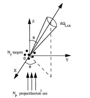
Figure 2.1: Schematic of the scattering of a monoenergetic parallel beam of projectiles from target particles at the origin in the laboratory co-ordinate system. After McDaniel (1989)
2.2 Collision cross section
The cross section is a measure of the probability that a given reaction will occur under a given set of conditions. For a particular collision it can be defined as the ratio of the number of collisions per unit time per unit scatterer to the flux of inci dent projectiles.
Consider a monoenergetic, parallel beam of particles incident on NT target parti cles located at the origin of a co-ordinate system (see figure 2.1). Assume elastic scattering of the incident point particles, Np, and a target density such th at ta r get particles do not shield each other. Further assume th at no incident particle is scattered more than once, that the target particles are at rest and that they are so massive relative to the projectiles that the laboratory and centre of mass frames are the same. Then dO,Lab represents an element of solid angle and Ns(9, 4>)dVtLab
[image:16.543.165.480.82.425.2]to the number of incident particles and the number of scatterers. The constant of proportionality is the scattering cross section, <rs, thus:
Ns(0, (f>)dClLab — (f))NpNTdQLab (2-1)
The differential scattering cross section (DCS) is defined as:
das(e, (j>) = <7S(0, (t>)dnLab = N s(e^ d n Lab (2.2) iv p l\rp
with dimensions of area. The differential cross section per unit solid angle becomes:
der s
d^lpab( M )
Ns(e^)
N pN T (2.3)
with dimensions of area per steradian. The cross section can then be considered as the area presented by each target particle for scattering of the projectiles into the element of solid angle.
The integral elastic scattering cross section, Qep is obtained by the integration of the elastic differential cross section over all (47r steradians) angles. When the DCS is symmetric about the incident axis, as it is for unpolarised projectiles and targets, it is independent of the azimuthal angle </> and
Q e i = [ -j^rdSl = [ [ sin OdOdcf) = 2n f sin 0d6 (2-4)
J dil J J dil J dil
When inelastic scattering channels are open in a scattering process, a grand total cross section is defined, which is the sum of the integral cross sections for all the open scattering channels.
The momentum transfer cross section is defined as:
r i r a
Q m t — / - ^ f ( l — cos 6)d£l = 2n / (1 — cos 6) sin QdO (2-5)
J d\l J dil
Where (1 — cos 9) represents the fractional change in forward momentum of the pro jectile. The momentum transfer cross section is also known as the diffusion cross
section. Both the integral and momentum transfer cross sections have dimensions of area.
2.3 Low energy elastic electron scattering from atoms
Consider the elastic scattering of low energy incident electrons from low-Z atoms, where relativistic effects can be neglected. The Schrödinger equation describing this scattering from a target atom with nuclear charge Z and N electrons is (Burke 1996):
E is the total energy of the system and the wavefunction of the scattered electron. The Hamiltonian is given by:
(2.7)
rij = |i*j — Tj\ where and are position vectors of the incident and scattered
electrons respectively, relative to the origin. The origin is the target nucleus which is assumed to have infinite mass. Target eigenstates, and their corresponding eigenenergies, Wi, satisfy:
Hn is defined by equation 2.7 with iV+1 replaced by N. The solution of equation 2.6 corresponding to a scattering process has the asymptotic form:
The incident wave term is the product of the initial state atomic wavefunction and the plane wave representing the incident electron with initial wave vector k *, magnitude ki along the z axis. The scattering wave term includes contributions from all energetically allowed target states and fji(9,(f>) is the scattering amplitude for each allowed transition. The equation
defines the differential cross section for a transition from an initial state |i) = |k*, <$*)
to a final state | j ) = |kj, $ j). Integral and momentum transfer cross sections are obtained by integrating over all scattering angles (section 2.2). Thus, once theory determines the scattering amplitude for a transition, any cross section can be com puted.
The Schrödinger equation for the scattering system is a second-order partial dif ferential equation in several variables. To solve this directly is impossible, and eigenfunction expansion methods can be used to reduce it to a set of equations which only depend on the radial co-ordinate of the scattered electron. A partial wave expansion of the total wave function is (Burke 1996):
— WiSij (2.8)
(2.9)
j
(2.10)
n
^ ( Xjv+i) = A $ [ ( x i , x N; rx+icrN+ i ) r n+i) t = i
(2.11)
m
Xtv+i = x i , x 2, ...,xtv+i represents the space and spin coordinates of all TV + 1 electrons;
Xi = ri(Ji represents the space and spin coordinates of the zth electron;
A is an operator which antisymmetrises the summation with respect to exchange of pairs of electrons in accordance with the Pauli exclusion principle;
—r
are the channel functions, obtained by coupling the orbital and spin angular momenta of the target eigenstates or pseudostates, 'Jq, with those of the scattered electron, forming eigenstates of the total orbital and spin angular momenta, their z
components and the parity operator 7r;
the relevant quantum number, T = L MlS Mstt, is conserved in the collision. L is the total orbital angular momentum and S is the total spin, while M L and Ms
are the corresponding magnetic quantum numbers;
Ffj are the reduced radial functions describing the motion of the scattered elec tron; and
x f are square integrable correlation functions allowing for additional correlation not included in the first expansion, with coefficients 6^.
Substitution of equation 2.11 into the Schrödinger equation, projecting onto the functions <f>j and x f and elimination of the coefficients frb produces n coupled integro-differential equations of the form:
where is the orbital angular momentum of the scattered electron, and V f, W f
and X f are local direct, nonlocal exchange and nonlocal correlation potentials re spectively. When the correlation potential from the x f terms in equation 2.11 is not included then equations 2.12 are often called the close coupling equations. The scattering amplitude, and hence the cross sections, are found by solution of equation 2.12. The reduced radial functions are subject to the reaction matrix (if-m atrix) asymptotic boundary conditions:
Ffj ~ hi 2 (sin 0i6tj + cos OiKf) open channels > 0
J r— V n o J
(2.13)
where
Qi = h r - -liTT +
Zt
Z - N
ln(2h r ) + argT ( + 1 - i(Z - N)
(2.14) These boundary conditions (equation 2.13) together with equation 2.12 are the Lippmann-Schwinger integral equation. The scattering matrix (5-matrix) and the transition matrix (T-matrix) are related to the /C m atrix by the matrix equations:
r _ I + iK^
I - z K r
T r = Sr - I = 2iK r I - iK r
(2.15)
where the Hermicity and time reversal invariance of the Hamiltonian ensures K r is real and symmetric and Sr is unitary and symmetric. Here I is a unit matrix. The scattering amplitude is expressed in terms of transition matrix elements:
= - ( 4 » ) 2<k,|T|k,> (2.16)
However, for elastic scattering by a neutral atom in a *S ground state, the expression for f(0) reduces to (Burke 1996):
1 oo
/ W = 2ik ^ (2i + 1)(e2i”' " 1)P |(cos0) (2 1 7 )
where l is the quantised angular momentum of the scattered electron, k it’s wave number, rft the phaseshift and Pi(cosO) the Legendre polynomial of degree l. From equation 2.10, the differential cross section then becomes:
da d£l
1
ypl
+ l)elT]l sin rjiPi(cos0)
/=o
(2.18)
which is, of course, the well known equation for the DCS derived from the method of partial waves. The solution of the Schrödinger equation by the method of partial waves can be found in most texts on atomic physics, see e.g. McCarthy and Weigold (1995), McDaniel (1989) and Bransden and Joachain (1983). The corresponding integral elastic and momentum transfer cross sections are then:
47T
Qei = y W + 1) sin2(r]i)
Z=0
(2.19)
and
4 71” ^
Once the scattering problem is formulated attention turns to the representations of the scattering potentials, which may be roughly characterised by the region of space in which they predominate. “Short range” static and exchange effects domi nate close to the target. Exchange and correlation potentials are non-local and the exchange potential vanishes exponentially at large r. A non-local potential is one which is energy dependent, because it involves an integral over the wavefunction of the scattered electron (McDaniel 1989). The static potential is the electrostatic interaction between the projectile and the target, assuming the incident electron does not perturb the target. This potential also vanishes exponentially. The po larisation potential is associated with the distortion of the target which must occur in response to the incident electron. This distortion is a long range effect, and the potential is given by (McDaniel 1989)
V(r) ->
r —» oo
1a
2r*
(2.21)
where a is the dipole polarisability. There are many potentials for describing the interactions between particles, some relatively simple, see for example the lists com piled in Flannery (1996) or McDaniel (1989), and some very complicated, see for example Lane (1980) and Burke (1994) and references therein.
2.3.1 Relativistic effects
As the atomic targets get heavier, i.e. as the nuclear charge, Z, of the target in creases, relativistic effects become important. There is a direct relativistic distortion of the wave function describing the scattered electron by the strong nuclear poten tial and there is an indirect effect caused by the relativistic change in the target charge distribution. Moreover L and S are no longer conserved, J = L + S becoming the “good” quantum number. In fact, the spin-flip process is allowed because S is no longer conserved.
Intermediate Z atoms may be treated by either adding relativistic terms to the Hamiltonian or by re-coupling of the K-matrices to yield transitions between fine- structure levels (Burke 1994, 1996). However, for high Z atoms the Schrödinger Hamiltonian must be replaced with the Dirac Hamiltonian.
Application of the method of partial waves to a symmetric potential again gives rise to relatively simple equations for relativistic scattering. The differential cross section is given by
where f(9) and g(9) are the direct and spin-flip amplitudes respectively.
f(6) = j (Z + l)e 17?I+ sin rtf + lelTJl sin 77^ Ip* (cos#) (2.23)
1=0 ^ ^
g(9) = — (eIT7' si nrji — et7?I+ sin 77^ | P / (cos 9) (2.24)
rjf are the spin-up and spin-down phaseshifts and P/(cos#) are the associated Leg endre polynomial functions. The corresponding total and momentum transfer cross sections are then:
and
(/ + 1) sin2 77+ + l sin2 rjl | (2.25)
_ 4tt y ^ f (,l + !)(/ + 2)
^ k2 (2/ + 3) sin - V
1+1)
1(1 T 1) . 2 / - - \
+ (2/TT) sm {"'
+ (21 + lX2i + 3) sin2(,?l+ ~
r?i+l ) }
(2.26)
2.3.2 Other effects
Another effect on the elastic scattering cross section which theoretical approaches must consider is that of temporary negative ions, or resonances. These arise from the temporary attachment of the incident electron to the atom. For direct scattering the phaseshifts, and hence the cross sections, are usually slowly varying functions of the incident electron energy. However, the occasional rapid variation in one, or several, phaseshifts can have an effect in the cross sections in the form of a rapid variation over a small energy range, referred to as a resonance.
The position of the poles in the T-matrix are determined by details of the potential
V, and a resonance may be considered a state of the compound electron-target system with a definite orbital angular momentum, l (McCarthy and Weigold 1995). The probability of finding this compound system at an energy, P , is a Lorentzian distribution about er , with a full width at half maximum of Tr . Application of the uncertainty principle provides the corresponding uncertainty in the lifetime for the resonant state, r r , where:
Tr Tr ~ h (2.27)
width of the He- ls(2 s2)2S resonance used for calibration of the scattering appa ratus (section 3.3.5) is 11.0 ± 0.5 meV (Kennerly et al. 1981), corresponding to a lifetime of 6.0 x 10⁻¹⁴ s. This is much longer than the time taken for an electron to cross the target region, which is about 10-15 s for a 1 eV electron, and justifies the concept of resonances as compound states. An extensive discussion of atomic negative-ion resonances can be found in Buckman and Clark (1994).
Thresholds for inelastic scattering processes may also influence elastic scattering cross sections. Cusps or rounded steps may appear in the cross section as a function of energy. Even below the energy threshold for a new scattering process virtual transitions may take place according to A t « hA E. Here AE is the energy deficit and A t is the time in which energy conservation may be violated (McDaniel 1989).
2.4 Approximation methods
Exact solution of equation 2.12 is not possible since the sum over l is infinite. There have, therefore, been many approximation methods developed. The general methods used by theorists to describe scattering systems studied in this project are described in the following subsections, although this is not a comprehensive list by any means. Further information may be found in Drake (1996) and various theoretical reviews, including Lane (1980), Gianturco and Jain (1986) and others mentioned in section 2.1.
2.4.1 T he B orn ap p ro x im atio n
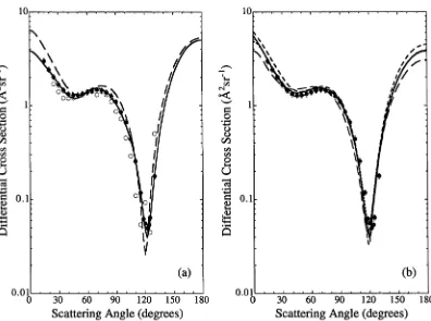
The method due to Born (1926) makes the basic assumption that the scattering potential is small and hence the interaction between particles may be treated as a perturbation. This is the case for high incident energy collisions and extremely long range interactions, which is why it is often used to calculate high-order phaseshifts. However, it may also be partially applicable to some low energy collisions where a long-range part of the interaction potential dominates, for example the dipole in teraction in low energy electron-polar molecule collisions. An example of this is the reasonably accurate results for very small angle inelastic scattering from CO (see figure 6.10).
In this approximation both the incident and scattered waves are treated as plane waves which remain undistorted by the interaction and electron spin and exchange effects are ignored.
in the exchange amplitude, g(0), and the approximation tends to overestimate the cross sections.
2.4.2 The polarised orbital approximation
This method attempts to incorporate the essential physics of the scattering process into the form of the wavefunction. As the electron approaches the target it induces electric multipole moments which, in turn, affect the electron motion. The method uses a trial wavefunction of the form:
¥ = A { [ $ i + <t>i}F(r)} (2.28)
where fa gives the polarisation distortion of the unperturbed target with wavefunc tion 4>j during the collision, and F(r) is the wavefunction of the scattered electron.
<j>i can be calculated by perturbation theory using a multipole expansion, then used to calculate an effective polarisation potential. This approximation is the basis of the theoretical calculations for elastic electron scattering from xenon by R. P. McEachran and L. A. Parcell (Buckman et al. 1997, Gibson et al. 1998), as de scribed in chapter 5.
2.4.3 Close-coupling approximations
Equation 2.12 is, in principle, a set of infinite coupled equations. It can, however, be truncated to obtain a finite set of equations, ideally small enough to be solved on a computer. The major role of the “higher” expansion terms is to participate in the polarisation during the collision (Lane 1980), hence a way of replacing the potentially infinite number of higher terms must be found. One replacement method uses “pseudostates” , carefully chosen to account for the polarisability of the target and the effects of open channels lost in the truncation. Another replacement adds an absorption or optical potential to account for flux lost into the open channels.
2.4.4 Convergent close-coupling
2.4.5 /^-matrix method
In this method configuration space is divided into two regions by a sphere of ra dius a. This is chosen such that the direct potential has achieved it’s asymptotic form and that exchange and correlation potentials are negligible for r > a. Then, for r > a, the collision is described by coupled differential, rather than integro- differential equations, often having analytical solutions. The aim is then to calculate the R-matrix by solving equation 2.12 in the internal region and then matching to the solution in the external region.
The R-matrix R^j(E) is defined by:
The problem is solved by expanding the wave function over a set of radial ba sis functions and diagonalising the resulting matrices as for other close coupling methods. It can also be solved in the inner region using matrix variational tech niques (Morrison 1983). This approximation is the basis of theoretical calculations for scattering from CO by L. A. Morgan (Gibson et al. 1996), described in chapter 6.
2.4.6 Matrix variational methods
The complex Kohn variational method begins with the expansion equation 2.11 where the reduced radial functions are chosen to satisfy complex T-matrix asymp totic boundary conditions. An integral is then defined in terms of the radial func tions and equation 2.12. This in turn defines a functional in the T-matrix which is made stationary for small variations about the exact solution. The reduced radial functions are expanded in a set of basis functions, with the T-matrix elements de termined as variational parameters (Burke 1996, Rescigno 1994, Nesbet 1983). The Schwanger variational method is based directly on the Lippmann-Schwinger in tegral equation. The T-matrix form of the Lippmann-Schwinger equation includes a multichannel outgoing wave Green’s function which may be found from numer ical solution of the asymptotic close-coupling equations. It can also be written to include reduced radial functions chosen to satisfy complex ingoing wave bound ary conditions. These combined yield a functional in the T-matrix which is made stationary for small variations about the reduced radial functions (Burke 1996, Luc- chese et al. 1983, Nesbet 1983).
2.4.7 Many-body calculations
Many-body perturbation theory may be used in calculations of electron scattering. The Hamiltonian is split into an unperturbed part, H0 and a perturbation H ' .
(2.29)
The complete set of unperturbed states are then used to calculate the eigenstates and eigenvalues for H in a perturbation expansion (Kelly 1985). In the approach of Johnson and Guet (1994), the initial spherically symmetrical potential is modified by the scattered electron. The correction to the initial potential is the electron self energy. This, when added to the initial potential defines an optical potential. The interaction of electron and optical potential is then governed by the quasi-particle equation. This equation is a single-particle equation. The electron self-energy is cal culated and the quasiparticle equation is solved in second-order perturbation theory.
2.5 Scattering from molecules
Section 2.3 describes the formulation of the problem for electron scattering from atoms. In this course of this project elastic and inelastic (ro-vibrational) electron scattering from molecules was also studied. Molecules in general have very low energy thresholds for inelastic processes and hence many open scattering channels. Perhaps most importantly from a theoretical point of view they are usually non- spherical and always involve a multicentre electron-molecule interaction potential. As a result there is a question of which co-ordinate system should be used to for mulate the scattering problem. The dynamic nature of the motion of the incident electron and the nuclei means the Schrödinger equation is non-separable, making numerical solution extremely difficult.
2.5.1 Reference frames
The molecular Schrödinger equation is:
(Hm + Te + V ) * = E * (2.31)
where Hm is the molecular Hamiltonian, Te is the kinetic energy operator of the scattered electron and V is the electron-molecule interaction potential. To solve equation 2.31, the theory may be formulated in the laboratory frame of reference and a set of coupled radial integro-differential equations obtained, analogous to equation 2.12 for atoms (Burke 1996). This incorporates the effects of nuclear motion on the electron which is allowed to respond dynamically to the motion of the nuclei. This method, however, requires the incorporation of huge numbers of rotational and vibrational nuclear quantum states, as well as energetically inaccessi ble states corresponding to the polarisation, which complicates the implementation (Morrison 1983).
interaction is relatively weak and in the first approximation the nuclei may be re garded as stationary. This is the Born-Oppenheimer approximation (unrelated to the inclusion of exchange in electron scattering calculations which is also called the Born-Oppenheimer approximation). This approximation is also referred to as the Born-Oppenheimer separation, as the motion of the nuclei and the electrons may be regarded as separated. The energy of a particular electronic state is calculated for different relative positions of the nuclei. The vibrational levels corresponding to the state are then calculated using the electronic potential curve and the rotational states are introduced as splitting of the vibrational levels (McDaniel 1989).
Invoking this separation of the electronic and nuclear motion, the electronic motion is first determined with the nuclei held fixed, hence it is also called the fixed-nuclei approximation. It can be adopted when the collision time is much shorter than the periods of molecular rotation and vibration. It is not valid when the energy is close to a threshold or corresponds to a resonance.
The molecular Schrödinger equation in the fixed-nuclei approximation is formulated as:
(Hel + Te + V)V = E V
H m = H ei - f Tr
(2.32)
where Hm is the molecular Hamiltonian, Hei is the electronic part of the target Hamiltonian when the molecule has fixed nuclei with co-ordinates R, Te is the ki netic energy operator of the scattered electron, V is the electron-molecule interaction potential and Tr is the kinetic energy operator for the rotational and vibrational
motion. R are usually formulated in the molecular or body frame. Solution of equation 2.32 then proceeds analogously to the solution for scattering from atoms using the same approximation methods.
2.5.2 Nuclear motion
One way to obtain cross sections dependent on the nuclear motion (e.g. rotational and vibrational cross sections) is to use the adiabatic nuclei approximation. When the Born-Oppenheimer approximation is valid the collision is regarded as “fast” , in that the collision time (~10-15 s) is much shorter than the period for nuclear rotation (~10-12 s) or vibration (~10~14 s). The electron adiabatically responds to the instantaneous position of the nuclei (Lane 1980) and is thus not sensitive to the instantaneous momenta of the nuclei. In this way the fixed-nuclei approx imation is made through all space. Once the fixed-nuclei scattering amplitude is calculated the effects of the nuclear Hamiltonian are introduced approximately by “averaging” the fixed-nuclei amplitude over the nuclear co-ordinates, R. There is a weighting factor in the averaging of the product of the initial and final target states
(Morrison 1983, Lane 1980).
While the close-coupling procedures are more accurate they are often impractical because they require the solution of huge numbers of coupled equations. The adia batic nuclei approximations on the other hand rely on assumptions which are often invalid, they fail near thresholds and resonances, for highly excited nuclear states, and for strongly polar targets. There have been hybrid approaches which partition the problems in various ways, for example the treatment of resonance scattering with close-coupling theory while the remainder of the problem is treated in the adiabatic nuclei approximation (Chandra and Temkin 1976a and 1976b). Or the inclusion of a kinetic energy operator, TVib, for the nuclear vibrational motion in equation 2.32 while continuing to treat rotational motion adiabatically (Burke 1996).
Resonances can strongly enhance inelastic processes. A non-local optical poten tial can be derived by application of resonance theory to the ro-vibrational close coupling equations (Nesbet 1983). Resonance theory is discussed in Burke (1996) and Temkin (1996). This optical potential is simplified to a local complex-valued potential function in practice.
In the R-matrix method vibrational motion can be included by derivation of a vi brational R-matrix from the fixed-nuclei electronic R-matrix (Schneider et al. 1979). A sequence of fixed-nuclei calculations is carried out on a grid of internuclear sep arations. It is then possible to compute a vibrational R-matrix and the implied 5-matrix for vibrational scattering (Nesbet 1983).
CHAPTER 3
Apparatus and Procedures
3.1 The apparatus
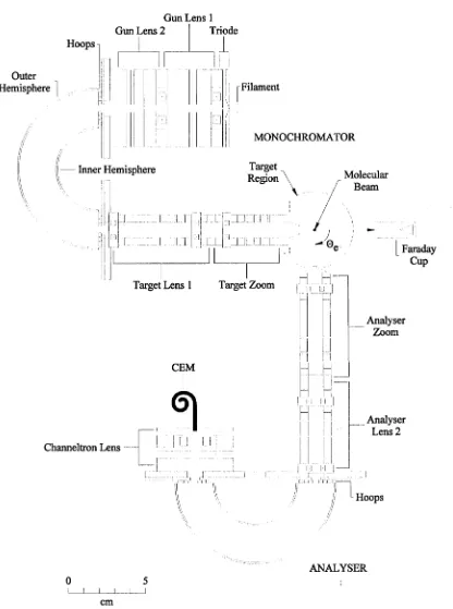
The apparatus used in this project is an electron spectrometer for measuring dif ferential scattering cross sections. It was originally constructed in 1986. Over the years it has been modified to allow access to a greater range of scattering angles, to allow application of the relative flow technique and to take data under computer control. The apparatus was fully described by Gulley (1994), and as a result this chapter will provide an overview of the apparatus and the methods used to obtain data. Only those modifications made during the course of this project will be de scribed in any detail.
The apparatus is a crossed-beam design in which a collimated, energy selected beam of electrons is crossed at right angles with a target (atomic or molecular) beam effusing from a capillary array (figure 3.1). The scattered electrons are detected by a channel electron multiplier at the exit of an electron analyser. This analyser rotates around the target beam axis, allowing an angular range of approximately —20° to 130°. Experiments are performed under computer control, with custom written programs handling data acquisition and the physical control of moving elements.
3.1.1 Vacuum system and physical characteristics
The experiment is performed in a high vacuum chamber. The experimental chamber is a cylindrical, non-magnetic (grade 310) stainless steel chamber 0.7 m in diameter and 0.5 m high. The chamber is pumped by a turbomolecular pump with a pumping speed of 550 1/s (Balzers TPU 510 U Plasma), mounted on the top of the chamber. This high pumping speed is required because the dynamic nature of the experiment produces a constant load on the pump under normal operating conditions. The turbomolecular pump is backed by a two-stage rotary-vane pump (Balzers DUO 016B/Halogen resistant).
Figure 3.1: View of the apparatus showing the monochromator, analyser and interaction region.
[image:30.543.13.530.24.585.2]
-H elm holtz coils
Turbo pump
Backing pump
Pump controllers
Co-netic shielding
Gas ballast tanks Counting electronics
Pneumatically controlled gas routing valves and manual needle valves
Figure 3.2: View of the exterior of the apparatus showing Helmholtz coils, co-netic shielding, gas ballast tanks and pneumatic gas control valves.
placed under the chamber. Thermocouple sensors (type K, nickel-chromium versus nickel-aluminium), in combination with a digital thermometer (Omega Engineering Inc. model 115KC) are used to monitor the temperature at various locations within the apparatus. The need for this procedure is minimised by always using high purity nitrogen to raise the pressure from high vacuum to atmospheric when the appara tus needs maintenance or modification. This avoids the initial adsorption of water vapour onto the walls of the chamber. The base pressure can reach 2 x 10⁻⁹ torr after the system has been baked and it is continually monitored by a Bayard-Alpert ion-gauge.
[image:31.543.31.529.20.762.2]supply is restored before the interlock is reset, the filament protection circuit of the ion-gauge controller ensures that power is not restored to the interlock if the pressure of the chamber has risen above that required to allow safe operation of the ion-gauge filament. The most recent addition to the interlock system is a pneumatic valve which closes the backing (forepump) line. This installation was necessary after a backing pump failure resulted in the interlock operating but failing to protect the system from backing pump oil creeping up the backing line.
3.1.2 Magnetic shielding
The path of a moving electron is affected by magnetic fields. In a magnetic field of 0.5 gauss (5 x 10⁻⁶ tesla), the typical field strength of the earth’s magnetic field in this laboratory, the path of an electron with a kinetic energy of 1 eV describes a spiral with a radius of approximately 3.4 cm. Given that the electron beam must be transported over distances of the order of 15 cm, is it is clear that the effects of this magnetic field need to be countered.
To counter the earth’s magnetic field the vacuum chamber is surrounded by three pairs of square Helmholtz coils arranged in a mutually orthogonal fashion (fig ure 3.2). The side length of each coil is approximately 2 m and the spacing between the pairs corresponds to 0.54 times the length of one side, which is the prescribed “Helmholtz spacing” for square coils (Firester 1966). The current in each pair of coils is adjusted until the magnetic field in the centre of the interaction region reads zero as measured by the probe of a flux-gate magnetometer (Schönstedt model DM2220) with a resolution of 10-9 tesla.
The cylindrical vacuum chamber is also surrounded by co-netic shielding (Perfection Mica Corp.) (figure 3.2), and there is also a cylinder of co-netic shielding inside the chamber. This nickel-iron alloy is a high permeability material and acts to further shield the apparatus from fluctuations in local magnetic fields. The external shielding is degaussed whenever it has been stressed, e.g. after removal to allow access to the apparatus, by passing 30A of AC (50Hz) current for about 2 minutes through cables inductively wound around the shield walls.
3.2 Electron optics
Gun Lens 1 Gun Lens 2 Triode Hoops
Outer Hemisphere
r
nr
: i
Inner Hemisphere
It
Channeltron Lens
CEM
Filament
MONOCHROMATOR
Target Region
I
ft
rtam ix
Target Lens 1 Target Zoom
T >!
r n ! ein
Molecular Beam
- 0 ,
H B;
I i-i [] j
u
M [•)
H H
Faraday Cup
Analyser Zoom
a 11
I i'i i't t
Analyser Lens 2
n
Hoops0 5
1 I I I I I
cm
ANALYSER
[image:33.543.55.471.96.655.2]analyser, essentially the reverse analogue of the monochromator, to determine the energy distribution of the scattered electrons. The monochromator comprises an electron source, a set of optics to collimate the electrons and focus them onto the entrance plane of an energy selector and a second set of optical elements to trans port the electron beam from the selector, focus it onto the interaction region and set the final energy of the beam. The first set of optics is known as the “gun assem bly” , and the set following the energy selector is known as the “target assembly”. The analyser comprises an “analyser assembly” , which sets the acceptance energy for scattered electrons and focuses them onto the entrance plane of an energy anal yser, and a “channeltron assembly” to accelerate and focus the electrons exiting the energy analyser onto the detector entrance. The detector is a channel electron multiplier.
3.2.1 Electron Monochromator
Electrons are produced from a conventional thermionic emission source, a hairpin filament of thoriated tungsten of diameter 0.1 mm. While other emitters are avail able the thoriated tungsten filament has a low work function, is easy to use and replace, is relatively inexpensive, spatially localises the electron emission and is re sistant to oxygen-bearing species. As a result it is not easily poisoned by molecular and/or corrosive gases, unlike alkaline-earth-oxide or carbonate emitters. In com parison to a pure tungsten filament it operates at a lower temperature, so that the Maxwellian distribution of the emitted electrons is narrower. The filament can be biased with respect to ground to account for contact potential effects between it and other electron optical elements.
com-Mounting plate
Channeltron j j n
Faraday cup
Analyser I Electron gun
Inner hemisphere I with electrostatic
I shielding Capillary array a
Field correction hoops
Faraday cage
around interaction region
F ig u re 3.4: View of th e sc a tte re d electron energy analyser em phasising th e in p u t optics, th e inner hem isphere an d th e field correction hoops.
mon choice for production and analysis of low energy electron beams for scattering experiments. The selector design includes field correction hoops within the hemi sphere to correct for fringing effects at the entrance and exit planes of the selector (Brunt et al. 1977c). The hoops are required to correct for the mismatch which oc curs between the cylindrical geometry of the electron optics and the hemispherical analyser. Figure 3.4 is a view of these correction hoops and the inner hemisphere of the energy analyser, the design of which is exactly the same as the energy se lector. The circular electrode hoops are adjacent to the entrance and exit plane, within the hemispherical region, and their operating voltages are determined from the expression:
V(r) = Vm ( ^ - l ) ' (3.1)
[image:35.543.33.527.26.761.2]To transport the now highly resolved electron beam from the exit plane of the se lector to the interaction region (figure 3.1), a target assembly of two, three element lenses is used, with the same optical properties needing to be controlled as in the gun assembly. Again two apertures are used to further collimate the electron beam in the target assembly. The target optics are constructed using cylindrical lenses. The angular range is constrained mechanically since, at angles greater than 130°, the electrostatic shielding of the electron analyser comes into contact with the elec trostatic shielding of the electron monochromator and, at approximately —20°, the analyser shielding comes into contact with support pillars inside the experimental chamber. The original design of the target optics used aperture lenses, which were substantially larger than cylinder lenses, and the angular range was restricted to angles less than 110°. The second lens in the target optics is a zoom lens, allowing, in principle, the image position to remain constant while the image energy varies between 500 meV and 50 eV, as selected by the final element of the target assembly (Harting and Read 1976).
is required to provide another adjustable voltage ratio (Hawkes and Kasper 1989). Here there are only three-element lenses, and as a result there is no control of the magnification of the image. To facilitate change between accelerating or retarding of the final electron beam energy with respect to the field free region of the tar get assembly, the three-element zoom lens has a movable lens centre such that it may have the object and image distance equal (symmetric mode), or the object distance slightly longer than image distance (asymmetric mode). When operating in symmetric mode the magnification of the lens is always around —1 (Gulley 1994), however operation in the asymmetric mode results in magnifications < —1. Fig ure 3.5 is a view of the monochromator showing the aperture lenses.
The volume where the incident electron beam intersects the molecular beam is defined as the interaction region. Based on measurements of the gas beam (Buckman et al. 1993) and calculated maximum magnification of the target zoom lens (Gulley 1994), the interaction region has a width of approximately 1.5 mm. A cylindrically shaped mesh, known as the target region, surrounds the interaction region (figure 3.1). This Faraday cage is maintained at beam energy and is designed to eliminate any stray fields by enclosing the exit of the monochromator, the en trance of the energy analyser and the capillary array, from which the gas effuses, in an electrostatic field free region. The entrance cone of the analyser penetrates the target region by means of a slit in the mesh which extends over the entire angular range of the analyser.
The electron beam passes through the interaction region and enters a Faraday cup (figure 3.6). The cup acts as both a beam dump and a current monitor. It consists of two concentric cylinders. The outer cylinder is 60 mm long with an inner diame ter of 8 mm and the inner cylinder is solid with a diameter of 6.5 mm and a length of 20 mm, with the final 5.6 mm of that cylinder tapering to a sharp point. Both parts of the cup are constructed of stainless steel (310). The voltage on the inner cup is 30V while the outer cup is maintained at beam energy. The cup is positioned on the electron beam axis and this constrains the movement of the electron energy analyser to a minimum scattering angle of approximately 60°. However, the cup is mounted on a swinging arm which can move it away from the interaction region under the control of a stepper motor, allowing the analyser to access forward scat tering angles, to approximately —20°.
3.2.2 Electron Analyser
Figure 3.6: View of the target region showing the Faraday cup aligned on the electron beam axis.
a diameter of 0.75 mm. Using extreme rays the (plane) maximum acceptance angle is 7.2° viewing an interaction region of maximum diameter 3.38 mm (estimated solid angle is 9.5 x 10⁻⁴ steradians). Treating the 0.5 mm diameter entrance aperture as a simple geometric aperture and calculating from the centre of the second aperture, the maximum plane acceptance angle should be 2.9° with an interaction region di ameter 1.65 mm (estimated solid angle 1.6 x 10⁻⁴ steradians). This is based on a magnification of 1 for the zoom lenses of the analyser and the monochromator (Gulley 1994). Using either of these estimates it is clear that the whole interaction region, with a maximum width of 1.5 mm (section 3.2.1), should be seen by the analyser. However, as will be shown in chapter 4 the apparent angular resolution of the apparatus appears much better than either of these figures, on the order of 1°, probably because the actual target region is much smaller than the maximum possible viewing region.
scattered electrons to vary. The object of this lens is the second of the defining apertures. The energy analyser is a hemispherical energy analyser of exactly the same design as the energy selector of the monochromator (figure 3.4). The final, channeltron lens assembly is a simple three-element lens designed to accelerate and focus the energy analysed electrons into the channeltron (figure 3.7). Acceleration is required as the efficiency of the channeltron is optimised for incident electrons of approximately 100 eV.
Figure 3.7: View of the channel electron multiplier mounted in its box.
3.2.3 Counting electronics
CEM
+HV
Output to
discriminator
3.2.4 Gas Handling System
Figure 3.9 is a schematic of the gas handling system. Ultra-high purity gas is trans ferred from commercial high pressure cylinders to large volume (125 litre) ballast tanks, where it is stored at a pressure of 300-500 torr (40-70 kPa). These tanks provide a stable, low driving pressure for the molecular beam source. The driv ing pressure is set manually by precision leak valves (Granville Phillips series 203) and measured by a temperature controlled (50° C) MKS Baratron pressure gauge (Model 315BD-00010-SPMC with a 270B Signal Conditioner and a Type 272 Tem perature Controller) located immediately upstream from the entrance of the gas to the chamber via a capillary array. Driving pressures are typically 0.2 to 1.0 torr, but may be as high as 2 torr. A third, 20 litre, gas ballast tank containing high purity nitrogen has been added to the gas handling system. This gas is used for calibration of the electron beam energy at low energies. This process is described in section 3.3.5. The driving pressure for nitrogen is also set manually by a precision leak valve.
Thermocouple Gauge
Pneumatic Interlock Valve Exhaust
Blower
Backing
Pump Turbo Pump
Overhead Backing
Valve
HIGH VACUUM CHAMBER
Ion Gauge *)
In-line Volume Capillary
Array
Small Volume Nitrogen Tank
Baratron Pressure Gauge
Leak Valve to control gas driving pressure
Pneumatic valves 1 to 7 for selective gas routing
GAS LINES OVERHEAD TO APPARATUS
T
Ultra High Purity Regulators i '
Experimental Gas Cylinders l .arge Volume
Ballast Tanks
Reference Gas