Int. J. Electrochem. Sci., 8 (2013) 11118 - 11124
International Journal of
ELECTROCHEMICAL
SCIENCE
www.electrochemsci.orgShort Communication
Fabrication of ZnO@TiO
2Core-Shell Nanotube Arrays as
Three-Dimensional Anode Material for Lithium Ion Batteries
Ruoshi Li1, Zhangyi Xie2, Hongliang Lu2,*, David Wei Zhang2, Aishui Yu1,*
1
Department of Chemistry, Shanghai Key Laboratory of Molecular Catalysis and Innovative Materials, Institute of New Energy, Fudan University, Shanghai, 200438, China
2
State Key Laboratory of ASIC and System, Department of Microelectronics, Fudan University, Shanghai, 200433, China
*
E-mail: honglianglu@fudan.edu.cn; asyu@fudan.edu.cn
Received: 8 May 2013 / Accepted: 15 June 2013 / Published: 20 August 2013
ZnO@TiO2 core-shell nanotube arrays are fabricated combining the anodization and atomic layer
deposition techniques. In this process, thin ZnO layers are coated onto the inner wall surface of the TiO2 nanotubes. The novel three-dimensional material is directly used as anode for lithium ion
batteries and exhibits excellent specific capacity, cycling performance, and rate capability. The enhanced electrochemical performance can be ascribed to the combination of high specific capacity of ZnO and the structural stability of TiO2 nanotube arrays. On one hand, the ZnO layer increases the
areal capacity of TiO2 nanotube arrays from 74 to 170μAh cm-2 after 200 cycles. On the other hand,
the special nanotubular structure not only buffers the volume change of ZnO during cycling and but also facilitates rapid ion diffusion.
Keywords: lithium ion batteries; anode; titania nanotube array; zinc oxide; anodization, atomic layer deposition.
1. INTRODUCTION
On one hand, transition metal oxides have been attracted considerable interest as anode materials for LIBs because they exhibited higher capacities and better safety compared to conventional carbonaceous materials [1-4]. Among them, ZnO has a theoretical capacity as high as 978 mAh g-1. However, it is rarely investigated in the LIB field because of its poor cycling ability [5, 6]. It is believed that low electronic conductivity and large volume change during charge/discharge process are responsible for the poor performance. Therefore some efforts have been made to overcome these problems by different methods such as coating [7], designing microstructures [8-11], doping with other materials [12-16] and so on. On the other hand, in recent years well-oriented TiO2 nanotube array
(TNTA) have shown promising prospect as an anode material for LIBs [17, 18]. As anode materials, they have the advantage of stable structure, large surface areas and excellent pathways for Li+ to transfer between interfaces. The only drawback is the low specific capacity of TiO2. Therefore various
approaches have been explored to improve the specific capacity of TNTA. One of those most effective approaches is utilizing core-shell structures by coating the pores of TNTA with high capacity active materials layers, such as Cu6Sn5, SnO, Fe2O3, etc [19-23].
So far as we know, there have been no reports on the combination of the advantages of high theoretical capacity of ZnO and stable structure of TNTA. In this work, ZnO@TiO2 core-shell
nanotube arrays (ZnO@TNTA) were firstly fabricated using the techniques of anodization and atomic layer deposition (ALD). It was expected that by virtue of ZnO coating layers the areal capacity of TNTA can be improved without any increase in volume and the unique nanotube structure of TNTA can restrain the volume expansion of ZnO to improve the cycling performance. To our knowledge, this is the first report about the design, synthesis of ZnO@TNTA and its lithium storage performance.
2. EXPERIMENTAL
TNTA were grown using a Ti foil in the electrolyte of 1 wt% NH4F, 10 wt% H2O and 89 wt%
glycol at 60 V for 1 h and annealed under air at 500 oC for 3 h to convert TiO2 from the amorphous to the crystalline form. Sequential fabrication that involves the formation of the desired ZnO-core layers without sacrificing the porous structure was conducted by ALD. A commercial ALD reactor (BENEQ TFS 200) was utilized to grow thin ZnO layers at 200 oC. Diethyl-zinc (Zn(C2H5)2, DEZ) and
water (H2O) were used as precursors for Zn and oxidant, respectively.
The morphologies of the TNTA and ZnO@TNTA were observed by scanning electron microscope (SEM, Hitachi, FE-SEM S-4800A) directly. The nanotube arrays were peeled off the Ti substrate, sonicated in ethanol and characterized by transmission electron microscope (TEM, JEOL JEM-2010F UHR). The composition was analyzed by an energy dispersive X-ray spectrometer (EDX) operated at 20 keV (Bruker, QUANTAX 400). The crystal structures were characterized by X-ray diffraction (XRD), which was performed on a Bruker D8 Advance X-ray diffractometer using Cu Kα radiation (1.5406 Å) from 10 to 90°. The X-ray tube voltage and current are 40 kV and 40 mA, respectively.
(Superstar1220/750, Mikrouna) filled with pure argon. The electrolyte solution was 1 M LiPF6 in
ethylene carbonate (EC)/diethyl carbonate (DEC) (1:1 by volume). The cell was assembled with as-prepared ZnO@TNTA, lithium metal anode and a Celgard 2300 separator. Charge/discharge experiments were performed on a battery test system (LAND CT2001A, Wuhan Jinnuo Electronic Co. Ltd, China) between 0.01 V and 3 V at a constant current density of 50 μA cm-2
. In this work, areal capacities (μAh cm-2
) are given because the applications of this novel nanoarchitectured electrode would be mostly thin film micro-batteries.
[image:3.596.148.449.475.705.2]3. RESULTS AND DISCUSSION
Figure 1. A schematic illustration of the preparation process for ZnO@TNTA
A schematic diagram of the preparation process used to fabricate ZnO@TNTA materials is shown in Figure 1. ZnO layers were grown on the wall surface of TiO2 nanotubes using ALD method.
[image:4.596.150.448.346.717.2]ALD technique was used to grow ZnO layers due to its capability of preparing uniform and conformal thin films as well as excellent thickness controllability and good step coverage on complex structures [24, 25]. Figure 2 (a1-a3) shows the typical SEM and TEM images of TNTA before ZnO coating. Highly ordered TiO2 nanotubes with inner diameters larger than 100 nm are vertically aligned on the
Ti substrate. After deposition of ZnO, the morphology of the nanotube arrays was also characterized by SEM and TEM (Figure 2 (b1-b6)). Figure 2 (b1-b3) display that the hollow structure is still retained, although the inner diameters of the nanotubes become smaller than that of the bare TiO2
nanotubes as a result of the encapsulation of ZnO core layers. The ZnO layer is consisted of nanoparticles which could be seen clearly at high magnification in Figure 2 (b4-b6). In brief, the images demonstrate that ZnO@TiO2 core-shell nanotube array were fabricated successfully combining
the techniques of anodization and ALD. This special structure is believed to facilitate the rapid mass transport and increase the surface areas. Moreover, the TiO2 nanotube might buffer the volume change
of ZnO during charge-discharge process.
Figure 4. Electrochemical performances of TNTA and ZnO@TNTA: (a) Charge–discharge profiles of TNTA, (b) Charge–discharge profiles of ZnO@TNTA, (c) Cycling performance of TNTA and ZnO@TNTA, (d) Rate capability of TNTA and ZnO@TNTA
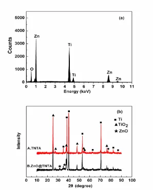
The chemical composition of the ZnO@TNTA was measured using EDX, as shown in Figure 3 (a). The peaks of Zn, Ti and O are clearly identified, indicating the possible existence of ZnO and TiO2. Figure 3 (b) gives the XRD patterns of the TNTA (spectrum A) and ZnO@TNTA (spectrum B).
In spectrum A, the diffraction peaks are ascribed to TiO2 and titanium substrate. Compared with
spectrum A, new diffraction peaks at 31.6° and 36.1° emerge in the XRD pattern of ZnO@TNTA (spectrum B), which correspond to (100) and (101) plane of ZnO (JCPDS, Card No. 89-1397). In addition, the peaks of TiO2 become weaker after the deposition of ZnO. The emergence of ZnO peaks
and the weakening of TiO2 peaks evidently confirm the successful growth of ZnO layers.
The electrochemical performance of TNTA and ZnO@TNTA were evaluated by galvanostatic discharge/charge tests. Figure 4 (a) shows their discharge/charge curves at a current density of 50 μA cm-2. In general, as anode materials for LIBs, TiO2 is usually discharged to 1.0 V and ZnO is normally
discharged to 0.01 V. For a better comparison, both TNTA and ZnO@TNTA were discharged to 0.01 V in this work. The TNTA shows potential plateaus at 1.75 V (Li+ insertion) and 2.0 V (Li+ extraction), which is in good agreement with the previous report about TiO2 [17]. It delivers a
discharge capacity of 127 μAh cm-2
and a reversible charge capacity of 92 μAh cm-2 in the first discharge/charge cycle, corresponding to a Coulombic efficiency of 72%. This value is similar to literature values [18-22], despite small variations of experimental conditions. For ZnO@TNTA (Figure 4 (b)), in addition to the discharge/charge plateaus of TiO2, there is a discharge potential plateau at
[image:5.596.118.480.90.341.2]
and 291 μAh cm-2, respectively, indicating a Coulombic efficiency of 68%. Figure 4 (c) displays the
discharge/charge cycling performance of the bare TNTA and the ZnO@TNTA at a current density of 50 μA cm-2
. The TNTA exhibit an excellent cycling stability: the charge capacity remains 74 μAh cm-2 after 200 cycles and the capacity retention is 80%. The capacity of ZnO@TNTA decreases in the first 20 cycles and becomes stable thereafter. As can be seen clearly, the charge capacity after 200 cycles remains 170 μAh cm-2
, which is more than twice of the bare TNTA. It demonstrates that the areal energy capacity was greatly improved due to the introduction of thin ZnO layer. In addition, the nanotubular structure of TiO2 buffers the volume change of ZnO during the charge/discharge process
and guarantees the good overall cycling stability. Figure 4 (d) reveals the result of the rate capability test for ZnO@TNTA. With the increasing current densities from 25 to 400 μA cm-2, the ZnO@TNTA deliver charge areal capacities of 268, 230, 193, 173, 155, and 140 μAh cm-2
at various rates. Finally, the charge capacity can recover to 249 μAh cm-2
with a capacity retention of 93% when the current density returns back to 25 μA cm-2
. The good rate and retention capability of ZnO@TNTA material are attributed to the unique core-shell nanotubular structure, which not only facilitates the Li+ diffusion but also lessens volume expansion during cycling.
4. CONCLUSION
A novel ZnO@TNTA composite material with a core-shell nanotubular structure was successfully fabricated by combining the techniques of anodization and ALD. Its excellent electrochemical performance as anode material for LIBs shows that this design is an efficient way not only to buffer the volume expansion of ZnO during cycling and facilitate ion diffusion, but also to enhance the specific capacity of TNTA greatly. In summary, the novel ZnO@TNTA material has been demonstrated to be a promising candidate of anode material for LIBs. Moreover, it is believed that the special strategy can be applied to synthesize other TNTA-based functional materials for versatile applications, such as solar cells, fuel cells, sensors, heterogeneous catalysis and so on.
ACKNOWLEDGEMENTS
The authors acknowledge funding supports from the “973” Program (No. 2013CB934103), the National Natural Science Foundation (No. 21173054, No. 51102048), SRFDP (No. 20110071120017), the State Key Research Program of China (2011ZX02702-002), and Science & Technology Commission of Shanghai Municipality (No. 08DZ2270500), China.
References
1. F. Wang, C. Lu, Y. Qin, C. Liang, M. Zhao, S. Yang, Z. Sun, X. Song, J. Power Sources 235 (2013) 67.
2. X.H. Huang, J.P. Tu, X.H. Xia, X.L. Wang, J.Y. Xiang, L. Zhang, J. Power Sources 195 (2010) 1207.
5. J. Liu, Y. Li, X. Huang, G. Li, Z. Li, Adv. Funct. Mater. 18 (2008) 1448.
6. Z.W. Fu, F. Huang, Y. Zhang, Y. Chu, Q.Z. Qin, J. Electrochem. Soc. 150 (2003) A714.
7. C.Q. Zhang, J.P. Tu, Y.F. Yuan, X.H. Huang, X.T. Chen, F. Mao, J. Electrochem. Soc. 154 (2007) A65.
8. X.H. Huang, X.H. Xia, Y.F. Yuan, F. Zhou, Electrochim. Acta 56 (2011) 4960.
9. M. Ahmad, Y. Shi, A. Nisar, H. Sun, W. Shen, M. Wei, J. Zhu, J. Mater. Chem. 21 (2011) 7723. 10.J. Liu, Y. Li, R. Ding, J. Jiang, Y. Hu, X. Ji, Q. Chi, Z. Zhu, X. Huang, J. Phys. Chem. C 113
(2009) 5336.
11.X.H. Huang, J.B. Wu, Y. Lin, R.Q. Guo, Int. J. Electrochem. Sci. 7 (2012) 6611.
12.F. Mueller, D. Bresser, E. Paillard, M. Winter, S. Passerini, J. Power Sources 236 (2013) 87. 13.X.J. Zhu, L.M. Geng, F.Q. Zhang, Y.X. Liu, L.B. Cheng, J. Power Sources 189 (2009) 828. 14.L. Xiao, Y. Yang, J. Yin, Q. Li, L. Zhang, J. Power Sources 194 (2009) 1089.
15.H.Q. Dai, H. Xu, Y.N. Zhou, F. Lu, Z.W. Fu, J. Phys. Chem. C 116 (2012) 1519.
16.Y. Sharma, N. Sharma, G.V.S. Rao, B.V.R. Chowdari, Adv. Funct. Mater. 17(2007) 2855. 17.H. Han, T. Song, E.K. Lee, A. Devadoss, Y. Jeon, J. Ha, Y.C. Chung, Y.M. Choi, Y.G. Jung, U.
Paik, ACS Nano 6 (2012) 8308.
18.J.R. Gonzalez, R. Alcantara, F. Nacimiento, G.F. Ortiz, J.L. Tirado, E. Zhecheva, R. Stoyanova, J. Phys. Chem. C 116 (2012) 20182.
19.Z. Wu, S. Zhang, L. Wang, Z. Du, H. Fang, Y. Ling, Z. Huang, J. Mater. Chem. 22 (2012) 11151. 20.L. Xue, Z. Wei, R. Li, J. Liu, T. Huang, A. Yu, J. Mater. Chem. 21 (2011) 3216.
21.G. Du, Z. Guo, P. Zhang, Y. Li, M. Chen, D. Wexler, H. Liu, J. Mater. Chem. 20 (2010) 5689. 22.G.F. Ortiz, I. Hanzu, P. Lavela, J.L. Tirado, P. Knauth, T. Djenizian, J. Mater. Chem. 20 (2010)
4041.
23.G.F. Ortiz, I. Hanzu, P. Lavela, P. Knauth, J.L. Tirado, T. Djenizian, Chem. Mater. 22 (2010) 1926.
24.X. Meng, X.Q. Yang, X. Sun, Adv. Mater. 24 (2012) 3589.
25.M. Liu, X. Li, S.K. Karuturi, A.I.Y. Tok, H.J. Fan, Nanoscale, 4 (2012) 1522.