Int. J. Electrochem. Sci., 8 (2013) 10976 - 10986
International Journal of
ELECTROCHEMICAL
SCIENCE
www.electrochemsci.org
Mesoporous Li
2FeSiO
4/C as Cathode Material for Lithium Ion
Battery
Hao Hao1,2, Jingjing Zhang1, Xiaoyu Liu1, Tao Huang1,*, Aishui Yu1,*
1
Department of Chemistry, Collaborative Innovation Center of Chemistry for Energy Materials, Shanghai Key Laboratory of Molecular Catalysis and Innovative Materials, Institute of New Energy, Fudan University, Shanghai 200438, China
2
Central Academe, Shanghai Electric Group Co., Ltd.
*
E-mail: [email protected] (T. Huang); [email protected] (A. S. Yu)
Received: 19 April 2013 / Accepted: 2 July 2013 / Published: 20 August 2013
Mesoporous Li2FeSiO4/C nanocomposite cathode material has been prepared by a sol-gel method
based on P123. Effect of calcinations temperature and carbon content on the electrochemical performance was investigated. The structure and morphology of the mesoporous materials were examined by X-ray diffraction, scanning electron microscopy, transmission electron microscopy and N2 adsorption/desorption techniques. The results indicate that the uniform nanometer-sized Li2FeSiO4
particles are embedded in irregular mesoporous amorphous carbon. The mesoporous Li2FeSiO4 with
9.22% carbon coating exhibits the best electrochemical performance especial rate performance. It has a high initial discharge capacity of 178.4 mAh g-1 at 1/16 C and reversible discharge capacity of 100.8 mAh g-1 at 5 C after 100 cycles. The enhanced electrochemical performance can be ascribed to its small size, large specific surface area, uniform carbon-decoration and mesoporous structure.
Keywords: Iron silicate; Mesoporous; Cathode material; Lithium ion batteries
1. INTRODUCTION
Lithium iron silicate, Li2FeSiO4 (abbreviated as LFS), is one of the most promising positive
electrode materials for next-generation lithium-ion batteries due to its low cost, environmental benignity and high theoretical capacity [1-6]. However, pristine Li2FeSiO4 has low electric
conductivity of around 10-14 S cm-1 [7, 8], leading to poor electrochemical performance. Carbon-decorating is an effective method to improve the electrochemical performance of Li2FeSiO4 cathode
g-1 [11]; ii) restrain the agglomeration of active material particles and make materials homogeneous under the calcinations process at high temperature (600-1000 ℃) [12]; iii) provide superior chemical and electrochemical stability [13, 14]. Carbon-decorated Li2FeSiO4/C composite with mesoporous
structure is considered as an effective method to improve the electrochemical performance of Li2FeSiO4. According to the diffusion formula t=L2/2D (where t is the diffusion time, L is the diffusion
distance, and D is the diffusion coefficient) [15], reducing the particle size and constructing porous structure can significantly shorten the diffusion time of Li+ in Li2FeSiO4, thus get much enhanced rate
performance. Recently, lots of efforts have been made through preparing of porous nanometer-sized Li2FeSiO4 cathode materials to improve their electrochemical performance. X.Y. Fan et al prepared
nanocomposite Li2FeSiO4/C with many irregular pores by sol-gel assisted ball milling technique,
which exhibited a lower initial discharge capacity of 134 mAh g-1, while 155 mAh g-1 after 190 cycles at 0.2 C [16]. Li2FeSiO4/C nanocomposite with pores between 5 and 20 nm were prepared by a sol-gel
method at the molar ratio 3:1 of TA/Li2FeSiO4, which showed a large specific surface areas of 64.4 m2
g-1 and a reversible capacity of 132.1 mAh g-1 at 1C [17].
Pluronic P123, a tri-block copolymer, was usually applied to prepare mesoporous silica materials SBA-15 by the assembly of P123 with silica species [18-20]. In this work, carbon-decorated cathode material Li2FeSiO4/C with mesoporous structure (abbreviated as LFS@C) was prepared by a
sol-gel method based on P123, which was employed as both carbon sources and mesopore forming agent for obtaining the mesoporous composite material. The effect of sintering temperature and carbon content on the electrochemical performance was systemically investigated.
2. EXPERIMENTAL
[image:2.596.77.502.502.736.2]2.1. Preparation
The schematic illustration of the synthesis procedure for the mesoporous Li2FeSiO4/C is shown
in Fig. 1. The mesoporous materials were synthesized using a sol-gel procedure followed by a solid-state-reaction synthesis route. Typically, 1 g Pluronic P123 (M=5800, sigma-aldrich) was dissolved into a mixed solution of 5 ml distilled water and 5 ml ethylene glycol (EG) under stirring until a uniform and transparent solution formed, and then 10.5 mmol LiCH3COO·2H2O and 5 mmol
Fe(NO3)3·9H2O were added in this order into the solution, which was stirring strongly for 1 h at 60 ℃.
Subsequently, 5 mmol TEOS was added dropwise slowly and the mixture was stirring and refluxing at 80 ℃ for 20 h. The obtained solution was gently heated at 50 ℃ to remove the excess solvent, and then aged at 70 ℃ until porous gel precursors were acquired. The precursors were sintered at 400 ℃ for 5 h, and then ground by a mortar and pestle. Three precursors were by further sintering at 600 ℃, 650 ℃, 700 ℃ for 10 h in an Ar-H2 (5%) atmosphere, respectively. They were labeled as LFS@C-1, LFS@C-2,
and LFS@-3, respectively. In order to investigate the carbon content on the electrochemical performance, three Li2FeSiO4/C materials with different contents of carbon coating were also prepared.
0.5 g, 1.5 g and 2.5 g P123 were used, respectively. And the final sintering temperature was fixed at 600 ℃. The obtained samples were labeled as LFS@C-4, LFS@C-5 and LFS@C-6, respectively.
2.2. Characterization
The structures of the as-prepared materials were characterized by X-ray powder diffraction analysis (XRD, Bruker, 4 Advance, D8, model) using Cu Kα radiation (λ=0.15406 nm). Morphological studies were conducted using scanning electron microscope (SEM, JEOL JMS 6390, Japan) and transmission electron microscopy (TEM, JEM-2100F, Japan). BET surface area measurement was carried out on an automated surface area and pore size analyzer (QUDRASORB SI, Quantachrome Instruments U.S.). The content of carbon in the composite was determined from the ignition loss of the sample at 800 °C in air with a thermogravimetric and differential thermal (TG/DTA) apparatus (DTG-60H, Shimadz).
2.3. Electrochemical measurements
The electrochemical properties of the as-prepared samples were assessed using CR2016 coin cells. For preparing the composite electrodes, a mixture of the active materials, super P carbon black and poly(vinylidene fluoride) (PVDF) at a weight ratio of 80:10:10, using 1-methyl-2-pyrrolidinone (NMP) as the solvent, was pasted onto pure aluminum foil. The electrode was circular with a 12 mm diameter and dried under vacuum at 80 ℃ for 12 h. The coin cells were assembled in an argon-filled glove box with lithium pellet as anode, a Celgard 2300 sheet as separator and 1M LiPF6 in a mixed
ranged from 0.001 to 100000 Hz with an amplitude of 0.005 V. All the tests were performed at room temperature.
3. RESULTS AND DISCUSSION
[image:4.596.157.431.211.394.2]3.1. Effect of roasting temperature on properties of mesoporous Li2FeSiO4/C
Figure 2. XRD patterns of (a) LFS@C-1, (b) LFS@C-2, and (c) LFS@C-3
Figure 3. SEM images of (a) LFS@C-1, (b) LFS@C-2, (c) LFS@C-3 and TEM images of (d) LFS@C-1, (e) LFS@C-2, (f) LFS@C-3
10 20 30 40 50 60 70 80
LFS@C-2
LFS@C-1
Inte
nsit
y
(a
.u.)
2(°)
LFS@C-3
[image:4.596.94.512.438.688.2]
XRD patterns of the as-prepared samples roasting at 600 ℃, 650 ℃ and 700 ℃ for 10 h are showed in Fig. 2. It can be seen that all the samples present the similar XRD patterns, which can be indexed to the space group P21/n [21]. The X-ray diffraction peaks of LFS@C-2 and LFS@C-3 are
more intense and sharper than that of LFS@C-1.
SEM images of the as-prepared LFS@C samples at 600 ℃, 650 ℃ and 700 ℃ are shown in Fig. 3a-c, it can be seen that all the samples display the homogeneous distribution of nanocomposite. However, particle agglomeration and increasing particle size can be obviously seen for LFS@C-2 and LFS@C-3. It demonstrates that the sintering temperature of 600 ℃ may be good for preparing LFS@C materials with uniform and smaller particle size. The TEM images of LFS@C materials prepared at different temperature are shown in Fig. 3d-f. LFS@C-1 and LFS@C-2 have similar particle size. However, the particle size of LFS@C-3 is bigger, which is nearly 3-4 times the size of that of LFS@C -1.
0 30 60 90 120 150 180 210
1.5 2.0 2.5 3.0 3.5 4.0 4.5 5.0
(a)
V
o
lt
ag
e
/
V
Capacity /mAh g-1
LFS@C-1 LFS@C-2 LFS@C-3
0 2 4 6 8 10
60 80 100 120 140 160 180 (b)
LFS@C-1 LFS@C-2 LFS@C-3
D
is
ch
ar
g
e
ca
p
ac
it
y
/
m
A
h
g
-1
Cycle number
[image:5.596.158.432.296.721.2]
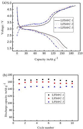
Fig. 4 shows that the initial charge-discharge curves and cycling performance of LFS@C materials at 1/16 C from 1.5 V to 4.8 V. It can be seen that LFS@C-1 exhibits the best electrochemical performance, which might be due to its smaller particle size and irregular porous structure. However, LFS@C-3 obviously exhibits the highest charge plateau, which might be ascribed to its large polarization resulted from larger particle size. The electrochemical results demonstrate that material obtained by sintering at 600 ℃ has the best electrochemical performance. Therefore, this temperature was selected as the final sintering temperature when preparing LFS@C materials with different carbon contents. TG results indicate that the carbon contents of LFS@C-4, LFS@C-5, LFS@C-6 are 7.03%, 9.22% and 11.15%, respectively.
[image:6.596.158.434.292.489.2]3.2. Effect of carbon content on properties of mesoporous Li2FeSiO4/C
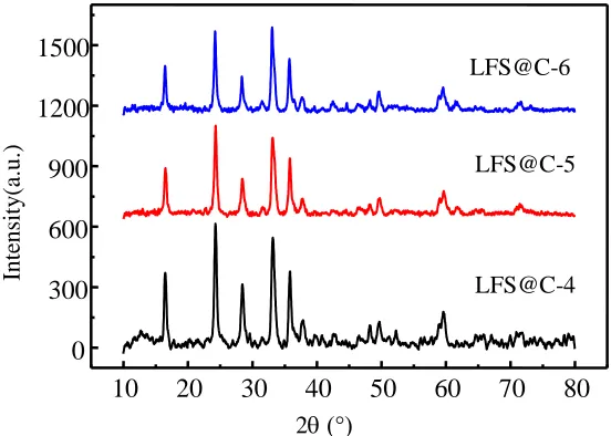
Figure 5. XRD patterns of LFS@C materials with different carbon contents
Fig. 5 shows XRD patterns of the as-prepared LFS@C samples with different carbon contents. The XRD patterns of LFS@C materials are similar with those of LFS@C materials prepared at different temperatures in Fig. 2. It demonstrates the LFS@C materials are pure and can be also indexed to the space group P21/n.
Fig. 6 shows SEM images and TEM images of the as-prepared LFS@C samples with different carbon content. From SEM images, it can be seen that all the samples exhibit uniform particle size of 20 nm or so. TEM images show that the uniform nanometer-sized Li2FeSiO4 particles embedded in
irregular mesoporous amorphous carbon, which might be beneficial to improve the electrochemical performance of Li2FeSiO4, because the in-situ formed amorphous carbons can serve as conductive
carbon network and mesoporous composite can be penetrated by electrolyte as to enable both Li+ and e- to migrate.
Nitrogen isothermal-adsorption determination was used to further investigate the pore structure of the as-prepared LFS@C samples with different carbon contents. Typical N2 sorption isotherms are
10 20 30 40 50 60 70 80 0
300 600 900 1200 1500
Int
ensi
ty
(a.u.
)
2(°)
LFS@C-6
LFS@C-5
shown in Fig. 7a. The total specific surface areas of LFS@C-4, LFS@C-5, LFS@C-6 are 69.36, 80.01 and 69.71 m2 g-1, respectively. It can be seen that LFS@C-5 has the largest specific surface area of 80.01 m2 g-1, which is also larger than previous literature [17].
Figure 6. SEM images of (a) LFS@C-4, (b) LFS@C-5, (c) LFS@C-6; and TEM images of (d) LFS@C-4, (e) LFS@C-5, (f) LFS@C-6
As shown in Fig. 7b, the Barrett-Joyner-Halenda (BJH) pore size distribution indicates that LFS@C-5 has a pore-size distribution of 3.5-14 nm and LFS@C-4 has a broader distribution, which are obtained by the volatilization and decomposition of EG and P123. It is noted that LFS@C-6 doesn’t exhibit obvious pore-size distribution.
0.0 0.2 0.4 0.6 0.8 1.0 0
50 100 150 200 250 (a)
LFS@C-4 LFS@C-5 LFS@C-6
V
o
lu
m
e
A
d
so
rb
ed
(
cm
3 g
-1 )
[image:7.596.162.422.550.738.2]
0 20 40 60 80 100 120 140 160 0.000
0.001 0.002 0.003 0.004 0.005 0.006 0.007 (b)
d
V
(
cm
3 g
-1 )
Pore Diameter (nm) LFS@C-4 LFS@C-5 LFS@C-6
Figure 7. (a) Nitrogen adsorption/desorption isotherms and (b) the pore size distribution plot calculated by the BJH formula in the adsorption branch isotherm for the as-prepared LFS@C samples with different carbon contents
It might be due to the adhesion between particles when the carbon content increasing, which is corresponded with TEM images. In general, the high specific surface area and uniform mesoporous should be in favor of intercalation/deintercalation of Li+ due to the large contact area between active material and electrolyte.
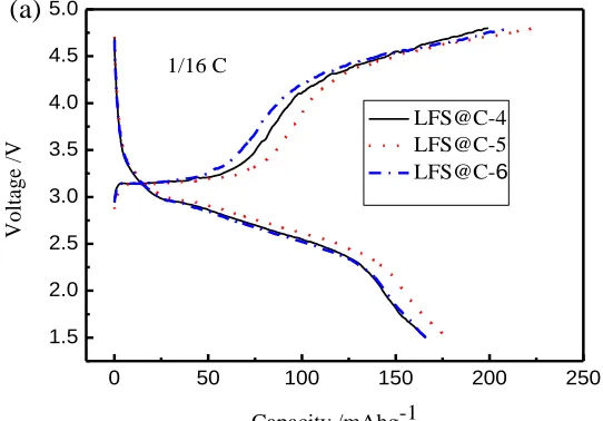
Fig. 8 shows the initial charge-discharge curves and cycle performance of the as-prepared LFS@C samples at 1/16 C from 1.5 V to 4.8 V. LFS@C-5 exhibits the highest initial discharge capacity of 178.4 mAh g-1, and 166.4 mAh g-1 after 20 cycles (93.3% of initial capacity), which can be ascribed to its easier migration of Li+ and e- in the electrode due to its smaller size of nanocomposite and the mesoporous texture decorated by carbon [22].
0 50 100 150 200 250
1.5 2.0 2.5 3.0 3.5 4.0 4.5 5.0
1/16 C
(a)
V
o
lt
ag
e
/V
Capacity /mAhg-1
[image:8.596.157.433.97.287.2] [image:8.596.160.431.557.746.2]
0 5 10 15 20
[image:9.596.164.424.97.288.2]0 30 60 90 120 150 180 1/16 C (b) LFS@C-4 LFS@C-5 LFS@C-6 D is ch ar g e ca p ac it y / m A h g -1 Cycle number
Figure 8. (a) Initial charge-discharge curves and (b) cycling performances of the as-prepared LFS@C samples with different carbon contents
LFS@C-4 and LFS@C-6 perform higher charge plateau than that of LFS@C-5, which means larger polarization. They only deliver discharge capacities of 133.2 and 145.5mAh g-1, respectively.
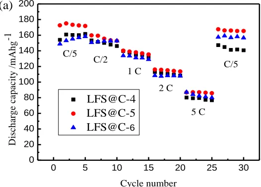
Fig. 9a shows the rate performance at 1/5C, 1/2C, 1C, 2C, 5C and 1/5C of the as-prepared LFS@C materials with different carbon content. It can be seen that the material LFS@C-5 exhibits the best rate performance, which delivers discharge capacities of 172.6, 159.7, 140.1, 116, 86.7 mAh g-1 at 0.2C, 0.5C, 1C, 2C, 5C respectively, and then return to 167.6 mAh g-1 at 0.2C after rate cycle. Fig. 9b shows cycling performance at 5C of the as-prepared LFS@C samples with different carbon contents. It exhibits zooming discharge capacity at the beginning and relatively stable capacity, especially for LFS@C-5, which can be ascribed to the electrical activation and electrolyte infiltration in mesoporous structure. LFS@C-5 exhibits high discharge capacity of 100.8 mAh g-1 after 100 cycles.
0 5 10 15 20 25 30
[image:9.596.161.424.547.736.2]
0 20 40 60 80 100
0 20 40 60 80 100 120 (b)
5 C
LFS@C-4 LFS@C-5 LFS@C-6
D
is
ch
ar
g
e
ca
p
ac
it
y
/
m
A
h
g
-1
Cycle number
Figure 9. different cycling performances and rate cycling performances of the as-prepared LFS@C samples with different carbon content
It could be ascribed to its small particle size of the nanocomposite, the large specific surface area and the unique mesoporous structure, which enhance the effective contact between the nanocomposite Li2FeSiO4/C and the electrolyte.
4. CONCLUSIONS
Mesoporous and carbon-decorated Li2FeSiO4/C nanocomposite cathode material has been
successfully prepared by a sol-gel method based on P123. The test results indicate that the LFS@C-5 material with the carbon content of 9.22% sintered at 600 ℃ has the best electrochemical property. For LFS@C-5, uniform nanometer-sized Li2FeSiO4 particles embed in irregular mesoporous amorphous
carbon with pore size of 3.5-14 nm. It also has the largest specific surface area. The superior electrochemical performance of LFS@C-5 could be ascribed to its small size, large specific surface area, carbon decoration and mesoporous structure. The nanocompostie with small particles can effectively reduce the diffusion distance of Li+ in Li2FeSiO4. The large specific surface area can
increase the effective contact area between the nanocomposite Li2FeSiO4/C and electrolyte.
Carbon-decoration can improve the electronic conductivity of Li2FeSiO4. The texture with mesoporous can be
infiltrated by the electrolyte in favor of Li+ migration in the electrode.
ACKNOWLEDGMENTS
[image:10.596.167.422.97.287.2]
References
1. A. Nyte′n, A. Abouimrane, M. Armand, T. Gustafsson, J.O. Thomas. Electrochem. Commun. 7 (2005) 156-160.
2. Z.L. Gong, Y.X. Li, G.N. He, J. Li, Y. Yang, Electrochem. Solid-State Lett. 11 (2008) A60-A63. 3. A. Nyten, S. Kamali, L. Hanggstrom, T. Gustafsson, J.O. Thomas, J. Mater. Chem. 16 (2006)
2266-2272.
4. D.P Lv, W. Wen, X.K. Huang, J.Y. Bai, J.X. Mi, S.Q. Wu, Y. Yang, J. Mater. Chem. 21 (2011) 9506-9512.
5. T. Muraliganth, K.R. Stroukoff, A. Manthiram. Chem. Mater. 22 (2010) 5754-5761. 6. S. Zhang, C. Deng, B.L. Fu, S.Y. Yang, L. Ma, Electrochim. Acta 55 (2010) 8482-8489. 7. R. Dominko, J. Power Sources 184 (2008) 462-468.
8. A. Kokalj, R. Dominko, G. Mali, A. Meden, Miran Gaberscek, J. Jamnik, Chem. Mater. 19 (2007) 3633-3640.
9. X.B. Huang, X. Li, H.Y. Wang, Z.L. Pan, M.Z. Qua, Z.L. Yu, Electrochim. Acta 55 (2010) 7362-7366.
10.H.Q. Li, H.S. Zhou, Chem. Commun. 48 (2012) 1201-1217.
11.X.B. Huang, X. Li, H. Wang, Z.l. Pan, M. Qu, Z.l. Yu, Solid State Ionics 181 (2010) 1451-1455. 12.J. Moskon, R. Dominko, R. Cerc-Korosec, M. Gaberscek, J. Jamnik. J. Power Sources, 174 (2007)
683-688.
13.J.M. Tarascon and M. Armand, Nature, 414 (2001) 359-367.
14.Z. Chen, Y. Qin, K. Amine and Y. K. Sun, J. Mater. Chem. 20 (2010) 7606-7612. 15.X. L. Wu, L.Y. Jiang, F.F. Cao, Y.G. Guo, L.J. Wan, Adv. Mater. 21 (2009) 2710-2714.
16.X.Y. Fan, Y. Li, J.J. Wang, L. Gou, P. Zhao, D.L. Li, L. Huang, S.G. Sun, J. Alloys and Compd. 493 (2010) 77-80.
17.Z.M. Zheng, Y. Wang, A. Zhang, T.R. Zhang, F.Y. Cheng, Z.L. Tao, J. Chen, J. Power Sources 198 (2012) 229-235.
18.S. Liu, H.Y. Zhang, X.J. Meng, Y.L. Zhang, L.M. Ren, F. Nawaz, J.Y. Liu, Z.Q. Li, F.S. Xiao, Microporous Mesoporous Mater. 136 (2010) 126-131.
19.Y.N NuLi, J. Yang, Y.S. Li, J.L. Wang, Chem. Commun. 46 (2010) 3794–3796. 20.P. Liu, S.H. Lee, E. Tracy, Y.F. Yan, J.A. Turner, Adv. Mater. 14 (2002) 27-30.
21.N. Yabuuchi, Y. Yamakawa, K. Yoshii and S. Komaba, Dalton Trans. 40 (2011) 1846-1848. 22.P. Balaya. Energy Environ. Sci. 1 (2008) 645–654.