Rochester Institute of Technology
RIT Scholar Works
Theses
Thesis/Dissertation Collections
2005
Hardware Software Synthesis of a H.264 / AVC
Baseline Profile Decoder
Stephen P. Joralemon
Follow this and additional works at:
http://scholarworks.rit.edu/theses
This Thesis is brought to you for free and open access by the Thesis/Dissertation Collections at RIT Scholar Works. It has been accepted for inclusion in Theses by an authorized administrator of RIT Scholar Works. For more information, please [email protected].
Recommended Citation
Hardware Software Synthesis of a
H.264 /
Ave
Baseline Profile Decoder
By
Stephen Paul Joralemon
A Thesis Submitted in Fulfillment of the Requirements for the Degree of Master of
Science in Computer Engineering
Approved By:
Supervised by
Visiting Assistant Professor Dr. Marcin Lukowiak
Department of Computer Engineering
Kate Gleason College of Engineering
Rochester Institute of Technology
Rochester, NY
Dr. Marcin Lukowiak, Visiting Professor
Primary Advisor - R.l T Dept. of Computer Engineering
Dr. Roy Czemikowski, Professor
Secondary Advisor - R.l T Dept. of Computer Engineering
Dr. Kenneth Hsu, Professor
Secondary Advisor - R.l T Dept. of Computer Engineering
Thesis/Dissertation Author Permission Statement
,
J3:,A~g" II~e f~F"-.e.. Dl:!~C>;:'€../2H
AR~wA,~
SO(-TwA2£ SytVntE£I$ C?,-=-'Name of author:
STE~
t-\E.N>.
J
012 ,q4£JIIloAl Degree:M
ASTt..I'L d~ $c II;:: ,v kf:Program: CQI"'II~U7£Q ~ N(",N€'iFf2.IN(" College:
\<.
ArE C-, (...E:..4-.) <2ty C " k U ; t;.. f "FI understand that I must submit a print copy of my thesis or dissertation to the RIT Archives, per current RIT guidelines for the completion of my degree. I hereby grant to the Rochester Institute of Technology and its agents the non-exclusive license to archive and make accessible my thesis or dissertation in whole or in part in all forms of media in perpetuity. I retain all other ownership rights to the copyright of the thesis or dissertation. I also retain the right to use in future works (such as articles or books) all or part of this thesis or dissertation.
Print Reproduction Permission Granted:
I, S-q=:Pt!.E tv
JaR
..At..-( naN , hereby grant permission to the Rochester Institute Technology to reproduce my print thesis or dissertation in whole or in part. Any reproduction will not be for commercial use or profit.Signature of Author: _ _ _ _ _ _ _ _ _ _ _ _ _ _ _ _ _ _ _ Date:
Print Reproduction Permission Denied:
I, , hereby deny permission to the RIT Library of the Rochester Institute of Technology to reproduce my print thesis or dissertation in whole or in part.
Signature of Author: _ _ _ _ _ _ _ _ _ _ _ _ _ _ _ _ _ _ _ Date: _ _ _ _ _ _
Inclusion in the
RITDigital Media Library Electronic Thesis
&Dissertation (ETD) Archive
I, , additionally grant to the Rochester Institute of Technology Digital Media Library (RIT DML) the non-exclusive license to archive and provide electronic access to my thesis or dissertation in whole or in. part in all forms of media in perpetuity.
I understand that my work, in addition to its bibliographic record and abstract, will be available to the world-wide community of scholars and researchers through the RIT DML. I retain all other ownership rights to the copyright of the thesis or dissertation. I also retain the right to use in future works (such as articles or books) all or part of this thesis or dissertation. I am aware that the Rochester Institute of Technology does not require registration of copyright for ETDs.
I hereby certify that, if appropriate, I have obtained and attached written permission statements from the owners of each third party copyrighted matter to be included in my thesis or dissertation. I certify that the version I submitted is the same as that approved by my committee.
Abstract
The latestvideo compression standard isajoint effortbetweenITUandMPEG known as
H.264/AVC. As with any video compression standard the H.264/AVC uses
computationally intensive algorithms to maximize performance. During decompression these algorithms must be applied in real-time, processing 30 frames a second. This can
be done in software, specialized hardware, or a combination of the two. Software
solutions allow for maximum portability and ease of design, but General Purpose
Processors (GPP) can not take full advantage of the parallelizable algorithms that the
H.264 decoder is based upon. Specialized hardware solutions, on the otherhand, allow concurrentdataandinstruction paths,but do not offerahigh levelof abstraction forcross platform development. Recent work
by
Xilinx has resulted in the advent of theMicroBlaze soft-processorthatis a stand alone microcontrollerbuilt fromanFPGA. The MicroBlazeprovidesa specialized hardwaremediumto run softwareon-chipwithVHDL
entities.
The goal of this thesis was to model and simulate a software hardware hybrid
H.264/AVC Baseline Profile decoder using VHDLand a soft-processor. Itwasproposed to divide all
highly
sequential calculations (run-length and CALVC decoding) and control data flow into software and perform the remaining calculations (prediction,inverse transform, inverse quantization,etc.) in hardware modules. The software runs on Xilinx'
s MicroBlaze soft-processor and the hardware was designed using VHDL. A major advantage of soft-processors over GPP's, is that it hardware instantiations reside
on-chip withthe processor. The software and MicroBlaze soft-processor were simulated
in a test bench and the results proved that the MicroBlazecould not handle the encoded
bit-stream in real-time. For this reason the hardware interface and hardware decoder
were never
fully
implemented. Thescope ofthe thesiscovers the H.264 BaselineProfilestandard, MicroBlaze processor, the implemented software solution, and the proposed
Table
ofContents
Overview 1
1.1 H.264 Overview 1
1.2 Soft-ProcessorOverview 3
1.3 HW/SW Hybrid H.264 Decoder Design 5
Background
Theory
72.1 Video Compression 7
2.1.1 FramesandFields 8
2.1.2 Color 8
2.1.3 Format 9
2.2 H.264/AVC Standard 11
2.2.1 Network Abstraction Layer(NAL) andVideo
Coding
Layer(VCL) 122.2.2 MacroblocksandSlices 13
2.2.3 Intra Prediction 14
2.2.4 Inter Prediction 17
2.2.5 TransformandQuantization 20
2.2.6
Entropy Coding
242.2.7
Deblocking
Filter 262.3 MicroBlaze Soft-Processor 27
2.3.1 Processor Architecture 27
2.3.2 Processor Busses 29
2.3.3 Interrupts, Breaks, andExceptions 32
2.3.4 Kernel andDrivers 32
HW/SW Hybrid H.264 Decoder Design 34
3.1 Hardware Architecture 35
3.1.1 AVC File Interface Module(External) 36
3.1.2 OPB
Relay
Module 373.1.3 AVC Decoder Core 39
3.2 Software Architecture 42
3.2.1 Software Design Process 42
3.2.2
Top
LevelFunctionality
433.2.3
Reading
theBit-Stream 443.2.4 AVC Decoder Core Interface 45
TestBenchandResults 46
4.1 Encoded Bit-Stream 46
4.2
Feeding
theDecoder 464.3 Results 48
Conclusion 51
5.1 Future Work 51
5.1.1 CAVLCCore 52
5.1.2 BufferCore 54
List
of
Figures
Figure 1: H.264 Baseline Profile Decoder [1] 2
Figure 2: MicroBlaze Core Block Diagram 4
Figure 3: YC,Cb
Sampling
Formats[,] 10Figure 4: H.264 Standard Profiles111 11
Figure5: NAL Format 12
Figure 6: Subdivisionof aFrame into SlicesandSliceGroups[8] 14
Figure 7: 4x4 Intra Prediction Patterns (sub-block) 15
Figure 8: 16x16 Intra PredictionPatterns131 16
Figure 9: Tree Structured Macroblock Partitions 17
Figure 10: Optimal Block
Partitioning
for IntraPrediction1'1 18Figure 11: Sub-pixel Mappings for InterPrediction11] 19
Figure 12: 16x16 Macroblock BlockOrdering151 24
Figure 13: Raster Scan Orders for
Decoding
24Figure 14: IPIC Bus ReadandWrite Sequence 32
Figure 15: HW/SW Hybrid H.264 Decoder 35
Figure 16: XPS HW/SW Hybrid Decoder Layout 36
Figure 17: H.264 Decoder HW/SWDivision
39
Figure 18: HW/SW Hybrid H.264 Decoder Test Bench 47
Figure 19: Proposed Hardware Design 52
Figure 20: CAVLC Core 53
Figure 21: Buffer Core 55
List
ofTables
Table 1: Video Formats 10
Table 2: PF
Look-up
Table 22Table 3:
Qstep
Look-up
Table 22Table 4: Exp-Golomb
Entropy
Code Number Ranges 25Table 5: coeff_tokenTable
Look-up
Table 26Table6: MicroBlaze Register Bank 28
Table 7:
SystemMemory Map
36Table 8: OPB
Relay
Signals 38Table 9: Hardware Address Table fortheH.264 Decoder Core 41
Table 10: Function
Calling
Tree 49Glossary
ASIC- Application
Specific Integrated Circuit - A specialized hardware designed aimed
at a specific application. Pg. 3.
AVC
-Advanced Video Code- The
latest video compression standardand topic ofthis paper, Pg. 1, 11, Section 2.2
BRAM
-Block Random Access
Memory
-Memory
located on-chipwiththe FPGA and availableto theMicroBlazesoft-processor, Pg. 5.CABAC - Context-Adaptive
Binary Coding
An efficient coding algorithm gearedtowards streamswith afixedtableoftransmitteddata,Pg. 10, 24. CAVLC
-Context-Adaptive Variable Length Code
-An encoding scheme used
by
AVCto encodedataat thebit-level,Pg. 25, Section 2.2.6.2 CODEC- Video
enCODerDECoderpair. Pg.7, 21.
DCT - Discrete Cosine Transform
-A matrix transformcommon in image and video compression standard that converts data fromthe spatialdomain into a
frequency
domain.Pg
1, 21.DMA- Direct
Memory
Transfer- Thetransfer ofdata
directly
betweentwo moduleson abuswithout goingthrough the mainprocessor. Pg. 5, 30.DSP
-Digital Signal Processor- Processor
with an architecture specifically designed for
digital signal computations.
Typically
DSP's provide parallel datapaths with anISA thatoffersvectorinstructions. Pg. 2-3. EDK- Embedded Development Kit
-Xilinxsoftwarekitthat providesforthedesignand integration ofcombined software andhardwaresolutions, Pg. 5.
FPGA - Field Programmable Gate
Array
- Aprogrammable logic chip with a high
density
of gate arrays. Pg.2. FSL - Fast Simplex Link - Asimplified bus that connects
directly
to the registers in a MicroBlazesoft-processorcore,Pg. 29, Section 2.3.2.1.GPP - General Purpose Processor - Typical
microprocessor available commercially
withoutanyspecializedhardware fortargetedapplications.Pg. 2. H.264-seeAVC.
HVS - Human Visual System - A term that
encapsulates the manner which humans sample and processvisual stimuli,Pg. 9.
IP- Intellectual
Property
- Withinthe scopeofthis paperIPrefersto modules design
by
Xilinxthatattachto a soft-processorbus. Pg. 26.IPIC - Intellectual
Property
Inter-Connect - A hardwaretemplate designed
by
Xilinx toconnecthardwaretoa soft-processorbus, Pg. 5,31. IPIF - Intellectual
Property
Interface - Theactual hardware interface that connects the
OPBto theIPIC,Pg. 5, 31. ISA - Instruction Set Architecture
-Set of program instructions that are available for a givenprocessor.Pg. 3, 21.
ITU- International Telecommunications Union- An
organization thatshares the goalin
standardizingvideo media,Pg. 1. LMB - Local
Memory
Bus-MicroBlaze's memory bus that is used to connect to
BRAM, Pg. 5, 29, 31, Section 2.3.2.2.. MPEG - Motion Picture Experts
Group
-An organization that shares the goal in standardizingvideo media,Pg. 1.
NAL
-Network Abstraction Layer- A layer
intheAVC encodingprotocolthatincludes
andidentifiesthecontentsof anAVCpacket ofdata,Pg. 11, Section 2.2.1.
OPB
-On-chip
Peripheral Bus - MicroBlaze's bus used to connect to peripheralsincluding
memory.Pg. 4, 30, Section 2.3.2.3.PLB
-Processor Local Bus A synchronous bus that connects the processor to high
speed andhigh-performance I/O. Pg. 4, 30, Section 2.3.2.4.
QP - Quantization Parameter
-Scaling
factor usedby
the decoderduring
inversequantization. Pg. 21.
RGB
-Red, Green, Blue - A Common
color space used for capturing and displaying
visualmulti-media.
Pg
7, Section 2.1.2.1.SAE - Sum ofAbsolute Errors- Method
ofcalculation to measure the error of a given
prediction.Pg. 15. VCL
-Video Code Layer - A layer in the
AVC encoding protocol that includes actual
videodata,Pg. 11, Section 2.2.1. VHDL- VHSIC
(Very
High Speed Integrated Circuit) Hardware Description Language - Languageusedto model and design hardware fromthegate level to algorithm
level.
Pg
2.XPS - Xilinx Platform Studio - Development
software that allows auserto design both
hardwareand software separately, thencombine andtest,Pg.35.
YCrCb- A
three component color-spacethatisused
by
AVC, Pg. 9, Section 2.1.2.2.1
Overview
1.1 H.264
Overview
As digital video entered the air waves, cable, and optical storage devices in a massive
scale two major standardization groups took on the field of video compression, the International Telecommunications Union (ITU) and Motion Picture Experts
Group
(MPEG). The ITU is recently known for its H.261 and H.263 publications while the
MPEG's claimto fame has beenthe MPEG-1 andMPEG-2 video standards. Beginning
in 1997 the two groups combined efforts to put together the next generation video
compression standard. In 2003theH.264, a.k.a.MPEG-4 Part 10, a.k.a. AdvancedVideo
Code (AVC), standard was finalized. The new standard offers several improvements to
itspredecessors (H.261, H.262/MPEG-2, andH.263) such as:[8]
? Variable block-sizes ranging from 16x16to 4x4
? Va pixel resolutionformotion prediction
? Multiplereference frames fortemporalresidualcalculation
? Introductionof aninteger formoftheDiscrete Cosine Transform
The new features target a 2x improvement in bit compression while yielding consistent
quality'91. Note that with improvements in compression come an increase in algorithm
complexity and thus computation load. The scope ofthis document concentrates onthe
decompressionsideofanH.264bit-stream.
It is the responsibility of the decoder to reconstruct the compressed data into a
representationoftheoriginal video signal. A block diagramofan H.264 decoder may be
found in Figure 1. Uponreception ofthebit-stream, it is sentthroughanentropy decoder
to extract the video header information and the actual video data. Next, the run-length decoderaddsany dataredundancies thatwere removedforcompression. The dataisthen
scaled,reordered, and sentthrough theinverse integer Discrete CosineTransform(DCT).
The resulting bits represent the spatial (intra) and temporal (inter) predications of the
encoder andthecorresponding differenceor residualfromthe actual values. A
history
ofwithintheencoder. The difference is combinedwiththeprediction togeneratethe actual
pixel values.
Finally
adeblocking
filter ispassed overthedatato smooth the image. TheH.264 standard defines three profiles ofoperation, Baseline, Main, and Extended, each
profile adds a level of
flexibility
to the standard. The Baseline Profile isthe onlyprofilecovered in the thesis. However, the hardware and software is modularized in a way to facilitatetheadditionoftheothertwo profiles.
F'n-1
(reference)
Inter Prediction
Encoded Bit Stream
S
Entropy Decoder
Intra Prediction
(reconstructed) Filter
uF',
CAVLC
Inverse Quantizer
Inverse Transform
Figure1: H.264 Baseline Profile Decoderm
Decompressing
a video sequence entirely on a GPP requires a large commitment which draws computational resources from other applications running on the same processor.As an alternative, specialized hardware such as an FPGA or DSP may be used to
decompress thevideo. An FPGA can process thebit-stream in fewerclock cyclesthana
single CPU that is
inherently
sequential.Following
this ideology, recent work has been done to model a H.264 decoder in VHDL[7]. However, hardware design is a timeconsuming process that does not offer the portability and
flexibility
of software. A design is often tightly coupled to specific hardware peripherals and very littlefunctionality
is abstracted.Consequently
hardware designs are ported with greater [image:11.523.88.447.158.422.2](ISA)
offers the advantages of specialized instructions to handle signal processingapplications. Several H.264 decoders runningon DSP's begantohit the markettowards
the end of 2004[IOH12]. Note that almost all the software solutions decode a max
resolution of352x288 (CIF).
An alternative H.264 decoder design would be a combined software hardware solution.
A new breed ofprocessing has become commercially availableallowingauserto turn an
FPGA into a microcontroller. This computational unit has been dubbedasoft-processor.
Hardware modules, or VHDL entities, can be accessed
by
the soft-processor providingthebenefits ofapipelined processor on-chip with parallelizable hardware instantiations.
The mainadvantageof asoft-processor over aDSP isthat hardware instantiations may be
developed on-chip with the processing unit aimed at performing specialized operations.
The soft-processor also provides a unique opportunity for design migration. That is, a
complete software application may be developed in an expedited manner. Bottlenecks
within the software can be identified and moved to hardware. Thus as a design
progresses the FPGA may be reconfigured for better performance without affecting
external hardware. Notethat a natural high-level division forthe H.264 standard exists
after run-length
decoding
and before inverse quantization.Everything
prior is naturallysequential and everything after parallelizableto some extent. For the decoder design the
run-length and entropy decoder will run on the MicroBlaze CPU and the remaining
calculations performedin aVHDLentity.
1.2 Soft-Processor Overview
Xilinx in fact offers three soft-processors.
They
are, listed inincreasing
complexity,PicoBlaze, MicroBlaze, andaPowerPC based microcontroller. The PicoBlaze is limited
to small applications that do not require a lot of processing. Although diverse, the
PowerPC is abit large forthisparticularapplication andwouldlengthenthedevelopment
time. Note that Xilinx also offers boards with PowerPC controllers on them; this is not
the same as a soft-processor. For thesereasons the MicroBlaze processor was chosento
controltheI/O and executethesoftwareside ofthedesign. MicroBlaze isableto address
following
is a summary of the MicroBlaze soft-processor based on documentationprovided
by
Xilinx. For a complete description ofthe MicroBlaze architecture, kernel,andprogramminginterface pleaserefertoreferences
[14]"[17].
MicroBlaze is a 32-bit load/store RISC processor (Figure 2) with 32 32-bit general
purpose registers to handle addressing, interrupts, and the instruction set. The
soft-processor architecture includes a 3-stage pipeline consisting of a fetch, decode, and
execute stage. The arithmetic logic unit provides a limited set of operations excluding
floating
point arithmetic.Memory
can be accessedby
byte (8-bit), half-word (16-bit),andword(32-bit). All dataand addresses arein
big
endianform.MDM
t
DebugLogicFSL
Local Link l/F
Address Side LMB l-LMB Instruction Cache l-OPB Program Counter
I
Control Unit Instruction Buffer Register Bank 32x32-bit MachineStatus Register Logical/ Shift Barrel Shifter Divider ALU Multiply J" Data Side LMB D-LMB Data Cache D-OPB PERIPHERALSInterruptController UART
[image:13.523.88.445.244.505.2]OPB CoreConnect Off-Chip Memory0-4GB Watchdog Timer General Purpose I/O OPBCoreConnect Timer / Counter Off-Chip Memory0-4GB Xilinx
Figure 2: MicroBlazeCoreBlockDiagram
There are three processor busses available and compatible to the MicroBlaze
soft-processor, all ofwhich arebased ontheIBMCore-Connectbus standards. Two ofthese
busses provideaccesstoexternal peripherals andVHDL modules,the
On-chip
PeripheralBus (OPB) andProcessorLocal Bus (PLB). The PLB is asynchronous bus thatconnects
theprocessor to high-speed and high-performance I/O. It has separate lines for address,
write operations to expedite I/O. The OPB is a general purpose bus with a simplified
interface. The dataread anddata write signals share a commondatapath; therefore, the
OPB does not permit concurrent read and write operations. All of the peripherals
connected to the OPB are memory mapped and accessible
by
writing or reading to thespecified address. Both the OPB and PLB support DMA to relieve the processor work
load while transferring data. The final bus is the MicroBlaze's Local Memory Bus
(LMB). The LMB connects the processor to internal on-chip Block RAM (BRAM).
BRAMcan beusedfor instructionmemory, datamemory, orboth.
Xilinx'
s Embedded Development Kit (EDK), the MicroBlaze development suite,
provides several templates to connect user defined logic modules onto the IBM
Core-Connect bus'151. Thetemplatesareknownas Intellectual
Property
Inter-Connects (IPIC)that provide a rangeofaddress, data, and status signals tocontrol and communicate with
anygivenVHDL module. The IPICused is based onthe
functionality
ofthe deviceandwhetherit needsto be a masterbus deviceor can functionas a slave. The IPICis further
wrappedinside an IP Interface (IPIF) modulethatis the actual connectionto thebus and
accesses the processor through a moduleknown as an OPB Arbiter (the Arbiter acts as
the actual bus controller). The IPIF layer is transparent to the user; only the IPIC needs
to be
directly
interfaced with. This gives aprogrammer quick access to thebus withoutan in-depth knowledge ofthe bus protocol.
Putting
the decoder into the IPIC moduleprovides platform independence within the EDK suite of processors. The IPIC is a
generic interface that will interface with all of the IPIF units and OPB that exist.
Any
future changes that Xilinx makes to the bus will be incorporated into theIPIF interface.
Portability
forfutureworkisone ofthe majordesigngoals ofthe thesis.1.3 HW/SW Hybrid H.264 Decoder Design
Thehardware/software hybrid decoderwasdeveloped using the Xilinx EDK suite. EDK
provides utilities for generating hardware (VHDL) modules, compiling and
linking
code(gcc), porting designs to ModelSim for simulation, and porting designs to Project
Navigator for mapping onto a specified FPGA. The overallhardware design connects a
hardware module was designed to connect both a partial hardware AVC Decoder Core
and AVC File Core interface to the MicroBlaze. The AVC DecoderCore takes a frame
of4x4 coefficient matrices and control data as input and outputs pixels of the decoded
frame.
It is the responsibility of the software to read the bit-stream from the AVC File Core, decode thedata, and sendtheresultingcoefficientsto theAVC Decoder Core. The AVC File Core was designed using VHDL to read an H.264 ASCII file and also provides a
veryprimitive writeinterface. Oncethe AVC Decoder Core has decodedafull framethe
software reads intheframe fromthe AVCDecoder Coreand writes itoutto file usingthe
AVC File Core. The resulting file contains pixel representations of the decoded video
2
Background
Theory
2.1
Video Compression
The aim of video compression is to minimize the amountofdatarequiredto represent a
given sequence of images and in turn reduce transmission payloads and storage
requirements. There aretwo categories ofcompression,whether indata, image, orvideo
processing, known as lossless and lossy. The former techniqueconstitutes that an exact
replica ofthe original image can be generated fromthe encoded data, no information is
lost. This technique is useful when the data has ahigh priority such as medical images.
Lossless algorithms involve
decreasing
data entropy without loss of information. Thesecond category, lossy, constitutesthat some information is lost and comprises much of
the transmitted data applications today. The goal of
lossy
algorithms is to remove lowpriorityor irrelevant data without
jeopardizing
theintegrity
ofthe video sequence. Themain design tradeoff is compression rate verse the quality of the decompressed video.
The more aggressive the encoder is the greater the reduction ofquality in the decoded
video. The H.264 Standard uses both
lossy
and lossless techniques. For example,run-length encoding (a lossless technique) is used to encode
binary
level information whilerounding and quantization(a
lossy
technique) isusedtoencode residualcoefficients.Video compression encapsulates the encoding, transmission or storage, and
decoding
ofdata. Transmission andstorage will notbe discussed in detailinthispaper; however, it is
worth noting since compression has a direct effect on bandwidth and capacity
requirements. An encoder decoder pair (CODEC) must agree on the compressed data
format inorderto sustain compatibility. Videocompression standards in fact only define
thecompressed data format. In
doing
so, encoder implementation and algorithmdesignisopenfor interpretation. Two encodersmay be entirelydifferent, butthe bit-streamthat
theyproduce must adhere to the standard. This method ofstandardization providesthat
2.1.1 Frames and Fields
A video stream is divided into frames that represent
digitally
sampled images that werecaptured atdifferent points intime. Each frame mayconsist of a single or multiple fields
(similar to MPEG-2)[8].
Commonly
a frame is divided intotwo alternating orinterleavedfields. One field contains the even rows of a frame while the second contains the odd
rows. Ifeachoftheinterleaved fieldswere captured atthesametime theresulting image
is referredto as a progressive frame. However, ifthe fields were acquired at subsequent
times the resulting image is known as an interlaced frame. The H.264 main profile
provides additional capabilitiesto takeadvantage ofinterlacedvideo characteristics.
2.1.2 Color
Allimageswhether standstill or part of a sequence are representedintheirdecompressed
state
by
picture elements known as pixels. For all intents and purposes a pixel is adiscretevalue representing itsanalog signalcounterpartinthe real world. The value of a
pixel may be presentedin several ways; a
binary
image can takeon a value of either '0'or '1',a grayscale imagecan takeon any scalar value (typically0-255),andto efficiently
represent a color image one must use at least a three dimensional vector for each pixel.
This vector may take many forms
including
RGB and YCbCr. The vector serves as amapping into agiven color coordinate system orcolor space.
2.1.2.1 RGB (Red-Green-Blue)
The RGB color space consists ofthree orthogonal axis representing the portion of red,
green, and blue light that exist in any given color.
Many
digital cameras and LCD'soperatein RGB colordomain. In suchdevices, a singlepixelconsists ofacombinedred,
green, and blue filter
dividing
light into athree dimensional vector.Unfortunately
thereare flaws in such a simplistic model. The RGB coordinate system is linear while true
colororlight is not. BothRGB andYCDCrshare thisconstraint. Thehumaneye is more
sensitive to green light than red or blue. Some
display
and capture systems double thenumber of green receptors to compensate; modeling closer to what a human would see
changes in luminance rather then color or hue. It is desirable to
directly
represent theintensity
at each pixeltomapto theHuman Visual System (HVS).2.1.2.2 YCbCr
YCbCr was derived to increase the resolution of luminance (Y) within the color space.
RGB maps three basis colors equally even though the human eye is more sensitive to
luminance ratherthen color. The magnitude ofthe RGB vector is more important than
the composition. The YCt>Cr space dedicates an axis (Y) to luminance to maximize the
resolution andinturnadaptto theHVS.
The Luma component (Y) is a weighted average ofthe red, green, andblue components
(Equation 1) where kr, kg, and fa, are some weighting factors. The chrominance
components, Cr and Cb, are derived from the Luma. There is also an unspoken
Cg
component that can be calculated either from the green component in RGB and Y
component in YCbCr or
directly
from the Cb and Cr components. The H.264 standardoperatesintheYCbCrcolorspace.
Y=krR+kgG+kB Eq.l
C=B-Y
Ch=R-Y Eq.2
Cg=G-Y
2.1.3 Format
There are several ways to spatially sample an analog image or video. The straight
forward approach would be a consistent rate across all components ofa color space, a
grid ofcolor components. However, to tailor to the HVS it is best to sample at higher
rates where the human eye is most sensitive. As far as the human eye is concerned,
intensity
has the highestpriority. Therefore,intensity
shouldhave thehighestresolution.Figure 3 demonstratesthree different sampling configurations in the YCbCr space. The
first, 4:4:4, samples atthe sameresolutionacross all components. 4:2:2implies thatthere
are twice as many Luma components as Chroma. To achieve this, the chrominance
naming. 4:2:0 sampling produces a single Cb and Cr for every four Y samples. The
chroma samples are located every other column between every two Luma rows.
Typically
each color component, whether a luma or chroma, ranges from 0 to 255requiring 24-bits torepresent a complete pixel in 4:4:4. 4:2:0on average uses 12-bits to
represent a singlepixel andisused inthe H.264standard.
%
\_) VJ^HP
%
%
%
vJO
%
((gk
(pij) \_)
%
%
o
%
o
0
%
o
%>
o
%
o
h
o
(0
o
4:4:4
o
o
o
o
\t"":':'J \ )
o
o
o
o
o
o
o
o
(^
)
o
o
o
o
4:2:2
(_) IntensityComponents
CrCbComponents
[image:19.523.91.443.132.410.2]4:2:0 0lain E.G.Richardson Figure 3:YCrCbSamplingFormats"1
Several video formats exist that span multiple sampling rates, image sizes, and frame
rates. Table 1 highlights afewthatmay be found in Appendix A in [1].
Format Luma Width Luma Height MBs Total LumaSamples
SQCIF 128 96 48 12288
QCIF 176 144 99 25344
QVGA 320 240 300 76800
CIF 352 288 396 101376
VGA 640 480 1200 307200
4CIF 704 576 1584 405504
SVGA 800 600 1900 486400
4VGA 1280 960 4800 1228800
SXGA 1280 1024 5120 1310720
16CIF 1408 1152 6336 1622016
4SVGA 1600 1200 7500 1920000
16VGA 2560 1920 19200 4915200
Table 1:Video Formats
[image:19.523.73.454.454.658.2]2.2
H.264/AVC Standard
The fundamentals of the H.264 standard are based on the accomplishments of its
predecessorsH.261 and H.263. The actual compression is achieved
by
removing spatialredundancy within a frame, temporal redundancy within a frame sequence, and data
redundancy within the bit-stream. Often the spatial domain is not the most efficient
space to work in.
Many
standards define atransform to convert data into thefrequency
domain such as the Fourier or Discrete Cosine Transform. The idea is that high
frequencies in an image may be removed withoutrisking the
integrity
ofthe data. It isquite difficult to separate high
frequency
data in the spatial domain, while in thefrequency
domain it is a simple threshold. The H.264standarduses an integerversionoftheDiscrete Cosine Transform(see Section 2.2.5).
Extendedprofile
Mainprofile
[image:20.523.162.363.279.509.2]j)lain E. G. Richardson
Figure 4: H.264 StandardProfiles"1
The H.264 defines three profiles within the overall standard; Baseline, Main, and
Extended (Figure 4). Each profile adds a level of
flexibility
and complexity to thebit-stream. The Baseline Profile includes all ofthe basic definitions in order to decode the
most basic compressed stream. The Main Profile defines
functionality
for interlacedvideo and Context-Adaptive
Binary Coding
(CABAC). CABAC is an efficient codingalgorithm geared towards streams with a fixed table oftransmitted data. The Extended
Profile defines additional slices (section 2.2.2) and data partitioning. Data partitioning
provides a prioritization scheme withintheencoded video.
Only
theBaseline Profile wasimplementedin this thesis; however, thehardware and software designs are modularized
suchthat the additional profiles may beadded inthefuture.
2.2.1 Network Abstraction Layer
(NAL)
and VideoCoding
Layer(VCL)
The H.264 bit-stream is divided and processed in two layers; the NAL and VCL. The
former is directed toward making the bit-stream transmission compliant and the latter
definesthe actual format thatencoded video data must adhereto. It is the responsibility
oftheNAL toencapsulatethe dataproduced
by
the VCL.StartCodePrefix Header Byte Payload
Figure5: NAL Format
[image:21.523.133.399.305.427.2]The H.264 NAL defines NAL units that packet the coded video and non-video data
(Figure 5). A NAL unit consists of a start jprefix, a single header byte, and the
corresponding payload. The first bit ofthe header is always zero (forbidden_zero_bii),
bits 1-2 representtheNAL reference ID (naljrefjdc), andbits 3-7
identify
what type ofdata (naljunitjype) iscontained within theappended payload. The
beginning
ofaNALunit is marked with a byte aligned NAL delimiter or start jprefix (0x00000001).
Within theNAL unit emulation_prevention_bytes (0x03) are usedto prevent a start code
prefix from occurring inthe data. NALunitpayloads are categorized into VCLand
non-VCLunits. Thepayload of aVCLunitcontains actual encoded video datathattranslates
into frames. The payload of a Non-VCL unit contains information that describes the
format ofthevideo andbit-stream. This information serves asheaders forthevideo data
known as parameter sets. A parameter set can apply to the entire video sequence
(sequenceparameterset) or to a set ofpictures (pictureparameterset) within the video
sequence. The NALreference ID (nal_ref_idc)within aVCL NALunit definestowhich
picture parametersetthe enclosedframe belongs. In turn, the picture parametersethas a
NALreferenceID to
identify
which sequenceparametersetit belongs to.As stated earlier the VCL contains the actual encoded video frames. The H.264 is a
block-based hybrid
decoding
standard[8]. That is, the image is broken down intorectangularblocks and bothtemporaland spatial predictions are performed. Theresidual
ofthe predictions and the predictions themselves are encoded into the payload within a
VCL NALunit.
2.2.2 Macroblocks and Slices
It is common for video compression standards to subdivide a frame into rectangular
blocks for processing known as macroblocks. All of ITU's recommendations starting
with the H.261 use this
blocking
method. The H.264 defines a macroblock as a 16x16luminanceregionand its corresponding 8x8chrominance values (refertoFigure 3). Note
that one of the major advances that the H.264 offers is the ability to encode
sub-macroblocks down to 4x4 lumina pixel and 2x2 chroma pixel blocks for motion
prediction (see Section 2.2.4). A seriesof macroblocksare groupedtogether into a slice.
An image may be composed ofa single or several slices. Furthermore, slices that share
properties can becombined into slicegroups. Slice groupshave no geometric constraints
and can take on many patterns such as a checker-board, alternating lines, and object
based (Figure 6). Macroblocks within a slice are processed in a raster scan order. The
slices aredecoded in theorderthattheyare read or received. A group ofNALunitsthat
result in a decoded picture are known as an access unit. Access units are optionally
marked with access unit delimiters.
i i i : : i iSlice#0 |
i i i i i
j. .j
i !Slice#1 ! ! ! !
ill: : :Slice#2 I
: i i i i
Framesubdividedinto Slices FramesubdividedintoSlice Groups
isnpe Grot
r
I 1 p#2
SliciGrou|)#0 ^ :
Slics G rou|i#1
_PL_ll_JH_pi_Ii
FramesubdividedintoSlice Groups FramesubdividedintoSlice Groups
W.Wiegand,G. J.Sullivan,G.Bjontegaard,A. Luthra Figure6:Subdivisionof aFrame intoSlicesandSliceGroups'81
The H.264 standard defines 5 different types of slices I, P, SI, SP, and B. A Baseline
Profilebit-stream may only include I and P slices. Foradescription ofthe other3 slices
refer to [1]. AnI slice contains macroblocks that are encoded using intraprediction.
P-slicescontain macroblocksthatareencodedusing both interand intraprediction. It isthe
responsibility ofthe encoder to determine which method yields the highest compression
rate and group them into slices accordingly. Intraprediction algorithms remove spatial
redundancy and uses adjacent previously encoded unfiltered macroblocks. Inter
predictionalgorithmsremovetemporalredundancyand use macroblocks from previously
encoded framesthathave been filtered.
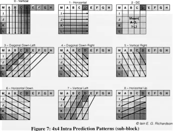
2.2.3 Intra Prediction
In intra prediction (I or P-slices) a block prediction is found using previously encoded
macroblocks that neighbor the current macroblock. Intra prediction may occur at both
theluma macroblock (16x16)and sub-block (4x4) levels. Thereare9possible prediction
modes for a sub-block and 4 possible prediction modes for macroblocks (Figure 7 and
Figure 8respectively). An8x8 chroma regionhas fourintraprediction modesthatmimic
the luma 16x16 modes. However, the ordering is different; DC (mode-0), horizontal
[image:23.523.114.404.28.282.2] [image:23.523.110.220.30.276.2](mode-1), vertical (mode-2), and plane (mode-3)[3]. Ifthe corresponding lumapixels are
encodedusing intra prediction the chroma pixels must follow suit. In order to calculate
the predicted values for thecurrent block pixels A-D and I-L must beprocessed (Figure
7). If E-H have notbeen encodedthen thevalue ofD iscopied into theirplace. Itis the
responsibilityoftheencoderto find theoptimalintraprediction mode. One measurement
of quality is to correlate the Sum of Absolute Errors (SAE), the smaller the SAE the
greaterthecompression rate[3]. Whenencoding, once a prediction modehas been chosen
theresiduals betweentheactual and predictedvalues are sent to the integertransformand
quantizerblocks Figure 1).
0-Vertical
1
-Horizontal
M A B Ci E F G H 1- J- K-.... , ' Mean(
-A-Jr-3-DagonalDown-Lefl M A B C E F G H
I
/
V
'/
J/
^
i;k
V
4-DlgonalDown-Righ M A B C D E F G H
I
\
J \ L\
Right 6 -HorizontalDownM, A B. c D E F G H
1 ^
^ 'v^ J^*V %
-M 1 A -Ve B rticaLett
P E F G H 1.
v
'/
/
J
/
/
K
J
/
I
/
/
-Horizontal
Up
M A B C 0 E F G H 1.
J,
K^
L.
[image:24.523.89.435.227.489.2])lainE. G. Richardson
Figure 7: 4x4 Intra Prediction Patterns(sub-block)
0-Vertical
1 1 1 1 1 1 1 1 1 1 1 1 1 II
vV;.,^;^;,-,'^...,,
1 -Horizontal J. I I I M I I I I
-I .. >
"'
of*'':
%'"'
a '''
&ff$4' 0/f:%
;;::'p'i
; ?
2
-Mean
i i i i i i i i i | ii i i r
Mean(H+
y)-3- Plane
[image:25.523.118.414.32.278.2]lainE.G.Richardson
Figure 8: 16x16 Intra Prediction Patterns[3]
The intra prediction mode for each block must be sent to the decoder adding additional
information and bits to the decoded stream. To limit the overhead required for intra
prediction further redundancy isremoved.
Neighboring
blocksoftenshare characteristicsincluding
their prediction modes. To take advantage of this commonality, both theencoder and decoder calculate the mostjprobablejnode of prediction for the current
block. Ifthe macroblock above and the macroblockto the left are within the same slice
and coded in 4x4 Intramode then the mostjprobablejnodeis the minimum mode ofthe
two. Note that the mode values are included in Figure 7 and Figure 8 next to the
corresponding prediction type text. Ifthe macroblock above and the macroblock to the
left are notofthe same sliceor encoded
by
other meansthen themostjprobablejnode isset to 2, DC. The encoder sends a
flag
for each 4x4 luma block telling the decoderwhetherthemostjprobablejnode isused or not. Ifanothermode of predictionis applied
then a 3-bit remainingjnode_selector is sent to
identify
which prediction method toimplement. Ifthe new prediction mode is less than the mostjprobablejnode then the
remainingjnodejselectoris set equalto the mode. Ifthe new prediction mode isgreater
than the mostjprobablejnode then the remainingjnodejselector is set to the new
predictionmode minus one. The remainingjnodejselectorcan onlytakeon values from
0-7 andthusonlyrequires4-bitstoencode
(including
themode flag).2.2.4 Inter Prediction
Inter prediction removes temporal redundancies in a video sequence, in essence it is
motion prediction. Inter prediction macroblocks must reside in P-slices and require a
history
ofpreviously encoded frames to be kept in memory. The encoder manages thereference frame buffer and communicates to the decoder viathe bit-streamwhat images
to
keep
in its buffer. The availability of multiple reference frames for motioncompensationis a newfeatureoffered withtheH.264standard.
For interprediction a 16x16 macroblock canbepartitionedinto any 4x4multiple. Figure
9 illustrates the tree structured partitions for H.264 interprediction. Ifthe macroblock is
broken into 4-8x8 blocks an additional field is added to thebit-streamforeach subblock
to specify whether or not and how the 8x8 sub-blockis partitioned. Chromablocks are
divided accordingto their lumacounterpart, i.e. the largestchromablockis 8x8 and the
smallestis 2x2. Chroma blocks arehalftheresolution ofthe luma.
16 16 8 8 8 8
16
8 0 8 0 1
0 16 0 1
8 1 8 2 3
Macroblockpartitions
0 1
0 1
2 3
Macroblocksub-partitions
[image:26.523.94.408.350.528.2]5 lain E. G. Richardson
Figure 9: Tree Structured MacroblockPartitions
Each macroblock partition has a motion vector and reference frame number associated
withit. Foran 8x8partition onlyone referenceframe may beused. All four 4x4 blocks
within an 8x8 partition must all use the same reference frame. The reference frame
number specifies which frame the prediction used and the vectorcorrelates to the block used within the referencedframe. Ifthe encoderdecides to divide amacroblockinto 4x4
partitions, it must send 16 motion vectors and reference frame numbers. It is up to the encoder to balance the trade offbetween the cost oftransmitting/storing motion vectors
and the savings of accurate motion predictionthatresultsin low energyresiduals. Figure
10 is an example taken from [1]. The image maps an encoder's attempt at the optimal
block partitioning for motion compensation. For ease of interpretation, the residual
betweenthe two frames is shown. A motion vectormust referto ablock inthereference
frameofthe same size.
[image:27.523.77.428.219.507.2]lain E. G. Richardson
Figure 10: Optimal BlockPartitioningfor IntraPrediction"1
One of the major improvements of AVC over H.261 and H.263 is V* luma pixel
resolution for motion prediction. The encoder can specify motion vectors that point to sub-pixel locations in a previously encoded frame. To calculate sub-pixels, the H.264 defines a method ofpixel interpolation. Ifthe motion vectoris an integral pixel value, i.e. does not refer to sub-pixels, then no interpolation is required. The interpolation is
carriedoutasfollows (referto Figure 1 1 forpixellocationreference).
aa
4x4Sub-block
[image:28.523.112.428.32.304.2]hh
Figure 11: Sub-pixel Mappingsfor InterPrediction111
5 H.264Standard
The sub-pixels at halfresolution that alignto either an integral columnor row (b andh)
are calculatedusing a 1-D FIR
6-tap
filter (Equation 3). The filter is applied eitherinthehorizontal or vertical direction. The result of the filter is then scaled using integer
mathematics without division (Equation 4). Note thatthe and operators specify a
bitshiftwhere '5' shiftsthe operand right5 bits.
bx =E-5F+20G+20H-5I+J
h{ =A-5C+20G+20M-5R+T
b=
{bl
+16)5h=
(h]
+16)5Eq.3
Eq.4
A zero threshold is applied to negative values and a threshold of255 appliedto positive
values. Halfresolution pixels thatare not aligned with an integral column or row (j) are
found in a similar manner. The 1-D
6-tap
filter (Equation 3) is used to find the halfresolution pixels correlating to cc, dd, hi, mi, ee, and ff. The filter is then applied a
seventhtimeto obtainji and scaled(Equation5andEquation6 ).
;',
=cc-5dd+20A, +
20m,
-5ee+ff Eq.5y=0,+512)10 Eq.6
Onceagaintheresult ispassed throughminimum(zero)andmaximum(255)thresholds.
Pixels that are located at quarter resolution locations, such as a, c, d, n, f, i, k and q, are
found
by linearly interpolating
(averaging) the adjacentintegral-pixelandhalf-pixel. Theinterpolated value is always rounded up
by
adding one prior to division (Equation 7). Ifthe Va resolution pixel ispositioned similarto e, g, p,or r, the interpolation isperformed
diagonally
(Equation 8). Note thatall corresponding chroma sub-pixels in thereferenceimageare found using strictly bilinear interpolation
a=(G+b+\)\ Eq.7
c=(b+h+\)\ Eq.8
Often adjacent inter predicted blocks have motion vectors that are similar. The H.264
standard takes advantage ofthis likeness when transmitting motion vectors. Both the
encoder anddecoderwillforma predictedmotion vectorbasedonthe surrounding blocks
that have been previously encoded and arein the same slice. The difference betweenthe
predicted vector and actual vector used
by
the decoder is transmitted. The method offormulating
aprediction changes accordingto thedimensionofthecurrentblock andthedimensions oftheblocks
directly
above,to theleft, anddiagonally
up andto theright.2.2.5 Transformand Quantization
Visual information contained within an image may be prioritized according to its
frequency. High
frequency
data shows up as edges or boundaries while lowfrequency
dataresides in smooth regions. Ifsome high
frequency
energy is removed fromaframeits image
integrity likely
remains intact.Removing
lowfrequency
or DC energyresultsin a
drastically
different image. Thusthe lowfrequency
data has high priority whilethehigh
frequency
data has low priority.By
transforming images from the spatial domaininto some formofthe
frequency
domain, low priority data may be easily removed. Notethatremoving high
frequency
data is achievedby
quantizationinthe H.264standard.The Discrete Cosine Transform(DCT) wasthe transformofchoiceforMPEG-1,
MPEG-2, MPEG-4, and H.263[5]. Although the DCT has proven advantageous, it requires
floating
point arithmetic. Some microcontrollers do not havefloating
point instructionsin their ISA and
floating
point operations complicate matters in hardware solutions. Ineither case extra clock cycles result. To simplify the CODEC transform the H.264
standard defines three transforms that only require simple 16-bit integer mathematics.
The primaryorcoretransform is in factanintegerversionoftheDCT. Forthederivation
pleasereferto [5].
2.2.5.1 4x4 Core Transformand Quantization
As discussed in the previous sub-sections the H.264 standard removes spatial (Section
2.2.3) and temporal (Section 2.2.4) redundancies within a frame. A prediction of the
current macroblock is formed based on either surrounding macroblocks or data from
previouslyencoded frames. The difference betweenthepredicted and actualdatais then
transformedintothe
frequency
domainduring
encoding.Y=
X =
Y=
-cfxc;
A l 1 1 T
xu
Xn
^13
^14
"1 2 1 1"
2 1 -1 -2
X2l
X22
-^23 ^24 1 1 -1 -2 1 -1 -1 1
x3i
xn
X33
X34
1 -1 -1 2-2 2
-lj
X4i
X42
X43 ^44 1 -2 1 -1= cjwci
1 1 1 1/2
]Z'u
7 7 7 1 ^13 *M4"
1 1 1 1
1 1/2 -1 -1 7 7 7 7
Z.23 Zv24 1 1/2 -1/2 -1 1 -1/2 -1 1
^31 7^32 7^33 ^347 1 -1 -1 1
1 -1 1 -1/2 .k,
7 7^43 7-^44J -1 1
1/2J
Eq.9Eq.10
Prior to quantization allresiduals are sent through the core transform(Equation 9) while
16x16 intra prediction incorporates 2-additional transforms. The core transform is
performed on all 4x4 residual luma and chroma blocks. Equation 10 illustrates the
inverse core transformwhose data is supplied from inversequantization. Iftheencoder
did not use 16x16 intra prediction mode then Y is sent through Equation 11 for
quantization. PF is apost-scaling factordetermined according toTable 2 where a =
Xi
and b=J^/C
.
Z:J
=round
PF
" Q
Eq.ll
Position(ij) PF
(0,0), (2,0), (0,2), (2,2) (1,1), (1,3), (3,1), (3,3)
mtim b2/4
else . ab/2
Table2:PFLook-upTable
Qstep
is a tablelook-up
factor (Table 3) determinedby
the encoderto achieve maximumcompression. The
look-up
table allows only the Quantization Parameter (QP) to be sentavoiding fractional numbers. Notethat
Qs,ep
doubles every 6 steps.QP
Vstep
0 1 2 3 4 5 6 7 8 9 10 11 12
0.625 0.6875 0.8125 0.875 1 1.125 1.25 1.375 1.625 1.75 2 2.25 2.5
QP 18 24 ... 30 36 ... 42 48 51
Qsteo 5 10 20 40 80 160 224
Table3:QstepLook-upTable
Inverse quantization within the decoder is achieved
by
applying Equation 12. And usingtheafore mentioned tables. Notethat there is ascaling factorof64x topreventrounding
errors'
. After inverse quantization, W is sent through the inverse transform (Equation
8).
Zi}=64Z..QslepPF Eq.12
2.2.5.2 4x4and 2x2 Transform for 16x16 Intra Prediction Mode
If a macroblock is encoded using 16x16 intraprediction then two additional transforms
are applied. The core transform must be applied 24 times to transform a 16x16
macroblock (16xforthe luma blockand4x foreach chromablock. Eachofthe 16-luma
transformations will yield a DC luma coefficient. Note that the DC coefficient will
always be located at Yn (Equation 13). The 16-luma coefficients are sent through a
[image:31.523.177.355.109.231.2] [image:31.523.43.491.324.387.2]Hadamard transform (Equation 14) and divided
by
2. The inverse transform is identicalwithout ascaling (Equation 12).
'
1 1 1 1
1 1 -1 -1
WD
=1 -1 -1 1
i1
-1 1 -1'-\
1 1 1"
*o
= 1 1 1 -1 -1 -1 -1 11 -1 1 -1
1 22 '32 '42 "32 "42 23 l33 J23 "33 '34 '24
1 1 -1 -1
1 -1 -1 1
1 -1 1 -1
"1 1 1 1
1 1 -1 -1
1 -1 -1 1
1 -1 1 -1
12 Eq.13
Eq.14
-V
The 4-chroma DC coefficients that result from 16x16 intra prediction mode are sent
through Equation 15 and quantized (Equation 11). For decoding, the coefficients are
rescaled and sent through the identical transform. After which the resulting DC
coefficients are reinserted into the 4x4 chroma block and the core inverse transform
performed.
W = 1 1
1 IT Y
JL 21 '22. 1 1
1 -1
Eq.15
2.2.5.3
Reordering
In the encoding path after transformation and quantization a macroblock consists of
16-4x4 luma coefficient blocks and 8-4x4 chroma coefficient blocks (Figure 12). If the
macroblock was compressedusing 16x16 intra prediction then an additional 4x4 and
2-2x2 coefficientblocks arecreatedfromtheDC coefficients. Insuchcases, theblocksare
sent to the entropy encoder starting with block -1 and
finishing
with block 25.Otherwise,blocks -1, 16, and 17 do not existandarethereforeexcluded.
The actual coefficients in a 4x4 block are sent in raster scan order (Figure 13). Frame
macroblocks are sentin zigzag order andfield macroblocks aresent in field scanorder.
16 J 0 J 1 J 4 IT 5 J 2 J 3 J 6 J 7 J 8 J 9 J 12 J 13 J 10 J 11 J 14 15 Luma
3 lain E. G. Richardson
[image:33.523.83.446.29.286.2]18 19 20 21 Cb j, 22 J 23 id 24 J 25 Cr
Figure 12: 16x16 Macroblock BlockOrdering151
--2
12
13
14
-16
Zig-ZagScan Field Scan
Figure 13: RasterScanOrders forDecoding
2.2.6
Entropy Coding
Entropy
codingtechniques are aimed atcompressing bit-level information. Inthe H.264standard most header information is encoded using fixed- and variable-length
binary
codes and actual data encoded using variable-length codes (VLC) or context-adaptive
[image:33.523.117.412.344.492.2]arithmetic coding (CABAC)[5]. CABAC is available in the main profile but excluded
fromtheBaseline Profile. Fora reference onCABACplease referto [5].
2.2.6.1 Variable Length Codes
The H.264 standard usesExp-Golomb entropy coding, and subtle variations, tocompress
the low-level bit-stream. All variations are based ongenerating a code numberand then
performing calculations based on the code number. Table 4 defines the first 62 code
numbers.
Bit-Stream Form Code Number Range
1
0 1X0
0
1-2
00 1 X, Xo
0 0 0 1 X2 X, X0
3-6
7-14
0 0 0 0 1 X3 X2 X, x0
0 0 0 0 0 1 X4 X3 X2 X, Xq
15-30
[image:34.523.122.399.187.297.2]31-62
Table 4: Exp-GolombEntropyCode Number Ranges
Thecode numberisfound
by
first countingthe numberofleading
'0's, excludingthe firstT, and reading an equivalent number of subsequent bits. The results are fed into
Equation 16toproducethecode numberorfinalunsignedExp-Golombresult.
CodeNumber=ue=
2kadi"gZer"Bi's
-\+X Eq.16
Ifsigned Exp-Golomb entropy coding isperformed, the decodermustthenplug the code
numberinto Equation 17.
1CodeNumber^
se=
(-!)'CodeNumber
Ceil Eq.17
The code number may also serve as an index (denoted as me in the standard) into Table
9-4 in [1]. The table determines which macroblock prediction method was used forthe
currentmacroblock.
2.2.6.2 Context Adaptive Variable Length
Coding
(CAVLC)4x4 lumina and chromaresidualblocks (Figure 12) are encodedusing CAVLC. CAVLC
begins
by
calculating a coefficient token (coeffjoken). The coeffjoken determines thenumber ofnon-zero coefficientsin the4x4 block and the number oftrailing 'l's
(up
to3). There are fourcoefficient token
look-up
tables (Table 5), each tailored to arangeofcoefficients. The H.264 uses previously encoded blocks that are in the same slice to
determine the appropriate
lookup
table (N). N is determined based on thelookup
tablesused in the upper (Nu) and left (NL) macroblocks as such; if both are available
thenN=
(Nu
+NL
)/2
, if only NL is available then N= NL, if only Nu is available thenN=Nu,elseN=0.
N Table forcoeffjoken
0,1
2,3
Num-VLCO
Num-VLCl
4,5,6,7
8
Num-VLC2
FLC
Table 5:coeffjokenLook-upTable
After the number of non-zero coefficients and number of trailing 'l's have been
encoded the sign of each trailing
'1'
is sent (0=+, 1=-) in reverse order. Ifthere are
more then 3 trailing 'l's onlythe last 3 are sent. Next the magnitude and sign ofeach
non-zero coefficient are sent in reverse order using 1 of 7 level
look-up
tables(Level_VLC0-Level_VLC6). The level
look-up
tableuseddynamically
changes accordingto predefined coefficient thresholds. Ifthere are greaterthen 10 non-zero coefficients at
first Level_VLCl is used, else Level_VLC0 is used. If a coefficient exceeds a certain
threshold the level
look-up
table is increased. Oncethe non-zero coefficients have beensent (according to the level look up tables), the number ofzerospreceding the last non
zero coefficient are encoded using VLC. Finally, the total number ofzeros proceeding
and number ofzeros
immediately
preceding each non-zero coefficient is sent in reverseorderusing VLC. Notethat thenumber ofzerospreceding thelowest
frequency
neednotbesent as itcanbecalculated fromthepreviousinformation.
2.2.7
Deblocking
FilterBy
partitioning the frame into macroblocks thedecoded image may have block artifacts.A higher degree of compression will increase the likelihood of
"blocked"
images. To
remedy this, a
deblocking
filter is passed over every 16x16 luma and 8x8 chromadecoded macroblock. Once the decoder abstractsthe transform coefficients and applies
the inverse transform, the 1x6 filter is passed over eachhorizontal and vertical4x4
sub-blockedge. Theexact filter and filter strengthusedare dynamically chosenaccording to
[image:35.523.188.338.155.231.2]the macroblock content and encoding method. For a detailed explanation of the
deblocking
filterreferto [2].2.3
MicroBlaze Soft-Processor
Xilinx has put together a development suite, known as the Embedded Development Kit
(EDK), which allows the user to turn anFPGA or portion of an FPGA into a processor.
In addition to the development environment, Xilinx provides a
library
of VHDLIntellectual
Property
(IP) Modules to incorporate into the processor design. This type ofconfigurableVHDL implemented processorhas been dubbed a soft-processor. Xilinx in
fact offers three separate soft-processor designs.
They
are, listed inincreasing
complexity, PicoBlaze, MicroBlaze, and PowerPC. Although diverse, the PowerPC is a
bit large for
decoding
anH.264 bit-stream andwould occupya large amount ofspace onthe FPGA. The Picoblaze is directed at small applications with limited instruction
memory. For these reason the MicroBlaze processor has been chosen as the decoder
platform. MicroBlaze is able to address enough RAM to executethe code required and
uses fewer gates then the PowerPC. The
following
is a summarized description oftheMicroBlaze basedondocumentationprovided
by
Xilinx.2.3.1 Processor Architecture
The MicroBlazeprocessoris a32-bit load/store RISC processor. Aswith mostload/store
architectures the MicroBlaze consists of a program counter, instruction decoder,
Arithmetic Logic Unit (ALU), and abankofregisters toexecutetheinstructionset.
The soft-processor architecture also contains an instruction bufferto facilitate pipelining
andtwo memory interfaces (IF); one for data and one for instruction. A Machine Status
Register(MSR)tracks thecurrent state oftheprocessor andretains information fromthe
last executed instruction such as divide
by
zero (DBZ),Carry
(C), Interrupt Enable (IE),etc. The MicroBlazealso provides stackinstructions and a stackpointer (SP)foreaseof
use.
The ALU provides simple integer arithmetic and integer operations (shift, barrel shift,
etc). There is no hardware within the processor architecture to support
floating
point(FP) instructions. This means thatthe compiler must break down any
floating
points and FP operations into integer arithmetic algorithms that consume several instructions and clock cycles. A programmer writing in a high level language must take into consideration thelatency
introduced with the use offloating
points. The register bank consists of34 32-bitregisters (Table 6). Notethatin realitythe programmeronly has fullreign over 23 "free" registers (R2-R12 and R19-R31). The remaining 9 registers are
dedicated to maintaining process flow. The "free"
registers are divided into two categories, volatile and non-volatile. Volatile registers do not retain their value across function calls while non-volatile register do. It is up to the programmer to push any
volatileregistersonthe stack priorto afunctioncall.
Register Type Purpose RO RI Dedicated Dedicated =0 Stack Pointer R2 R3-R4 Dedicated Volatile
Read-onlysmalldataarea anchor
Return Values R5-R10 R11-R12 Volatile Volatile Passingparameters/Temporaries Temporaries R13 R14 Dedicated Dedicated
Read- write smalldataarea anchor
Return addressfor Interrupt
R15 R16
Dedicated Dedicated
Return addressfor Sub-routine
Return addressforTrap
R17 R18
Dedicated Dedicated
Return Address for Exception Reservedfor Assembler R19-R31
RPC
Non-volatile Special
Mustbesaved acrossfunctioncalls
[image:37.523.125.399.244.449.2]Program Counter RMSR Special Machine Status Register
Table 6: MicroBlaze Register Bank
2.3.1.1 Pipeline
The MicroBlaze architecture consists of 3-pipeline stages; fetch, decode, and execute.
Each stage may work on a concurrent instructionprior to the completion ofthe current
instruction. The processor assumes that every branch is not takenresulting in a 1-cycle
penalty for branching. A 2-cyle penalty is avoided
by
allowing the instructionimmediately
afterthebranchtoexecute.2.3.1.2 Cache
The hardware designer has the option to include an instruction and data cache
(implemented via EDK). The cache is provided to optimize larger designs that require
external memory. Hereafter external memory refers to memory that is not located
on-chip with the FPGA while internal memory refers to the Block RAM (BRAM) that is
providedon-chip withthe FPGA. The instructionanddatacachereside in localmemory.
In cache2-bits are appended to signify whether an instruction oraddress is cacheable or
non-cacheable. In total memory may contain 1-GB of cacheable memory and 3-GB of
non-cacheable memory. An address incache is divided into atagaddress and cacheline.
The cache line can be 9 to 14 bits yielding a 4kB to 64kB cache respectively.
Every
instruction fetch is sent to cache and primary memory via the address bus.
Primary
memory is located either in local memory, external memory, or a combination. Ifthe
address is in non-cacheable memory then the cache ignores the fetch. Otherwise the
cache performs a tag
look-up
to see ifthe line is incache, ifso it returnsthe data. Ifthedata is not incache then theprocessormust waitfor primary memorytoreturn.
2.3.2 Processor Busses
There are four bussesavailable and compatible withtheMicroBlaze soft-processor. One
of the busses provides access for high speed peripherals (FSL), another connects the
processorto local dataand instruction memory (LMB), andthe finaltwo busses serve as
general accesslinestobothperipherals and external memory.
2.3.2.1 Fast Simplex Link(FSL)
The MicroBlaze has access to 8-master and 8-slave Fast Simplex Link Interfaces. The
FSL bus is implemented ontheFPGAas aFIFO. Each FSL interface containstwo 32-bit
widebuses, one forreadand theother forwrite. The FSLis designed to provide access
to oneway streaming data. Each interfacecontains abit that specifiesthedirectionofthe
bus. An FSL interface allows the processor to
directly
communicate with peripheralswithout sharing the data lines with other modules. This is very useful for signal
processing, image processing, network processing,
etc.[14]
The FSL expedites
communicationfor high prioritycontrolanddataacquisition. When multipleMicroBlaze
processors are placed on a single FPGA the FSL is typically used for inter-processor
communications.
![Figure 8: 16x16 Intra Prediction Patterns[3]](https://thumb-us.123doks.com/thumbv2/123dok_us/122312.11856/25.523.118.414.32.278/figure-x-intra-prediction-patterns.webp)