TRAINER of MOBILE PHONE
mod. CTS2/EV
Volume 1/2
THEORY AND EXERCISES
CONTENTS
Page
1. INTRODUCING THE CELLULAR NETWORK 1
1.1Concept of Cellular Network 1.1.1 Handover
1.2Analog Cellular System 1.3GSM Digital System
1.4Architecture of a GSM network 1.5Network Service Areas
1.5.1 GSM Service Area 1.5.2 PLMN Service Area 1.5.3 MSC/VLR Service Area 1.5.4 Location Area
1.5.5 Cell
1.6Techniques of multiple access 1.7Transport technologies
1.7.1 1G 1.7.2 2G 1.7.3 2.5G 1.7.3 3G
2. COMPONENTS OF A CELLULAR NETWORK 16
2.1 Mobile Station (MS) 2.1.1 SIM card
2.1.2 SIM card Phase II 2.1.3 Electric characteristics 2.1.4 SIM Locking
2.1.5 Mobile Equipment (ME) 2.2 Base Station Subsystem (BSS)
2.2.1 Base Transceiver Station (BTS) 2.2.2 Base Station Controller (BSC) 2.2.3 Cell topology
2.3 Network Sub-System (NSS)
2.3.1 Mobile Services Switching Center (MSC) 2.3.2 Gateway Mobile Switching
2.3.3 Home Location Register (HLR) 2.3.4 Visitor Location Register (VLR 2.3.5 Authentication Center (AuC) 2.3.6 Equipment Identità Register (EIR) 2.4 Operation and Support Subsystem (OSS)
Page
3. AIR INTERFACE 34
3.1 Noises and Interferences 3.1.1 Co-channel interference 3.1.2 Sideband splash
3.1.3 Doppler effect 3.1.4 Fading
3.1.5 Diversity
3.2 FDMA/TDMA multiplexing
3.2.1 FDMA multiplexing and frequency reuse 3.2.2 TDMA multiplexing
3.3 Handover
3.3.1 Intracell (Channel-Channel) Handover 3.3.2 Intercell / Intra BSC / BTS – BTS Handover 3.3.3 Intercell / Inter BSC / BSC - BSC Handover 3.4 Logical channels
3.4.1 Traffic CHannel (TCH) 3.4.2 Broadcast CHannel (BCH)
3.4.3 Common Control CHannel (CCCH) 3.4.4 Dedicated Control CHannel (DCCH) 3.5 Radio Link Failure
3.6 Random Access 3.7 Access Class 3.8 Structure of Bursts
3.9 Base Station Colour Code 3.10 Dynamic Power Control (DPC) 3.11 Radio link measurements
3.11.1 RxLev 3.11.2 RxQual 3.12 Voice coder
3.12.1 Codec/Decodec
3.12.2 Enhanced Full Rate (EFR) 3.12.3 Half Rate (HR)
3.13 Channel coding 3.14 Modulation
3.15 Multipath Equalization
3.16 Discontinuous Transmission (DTX) 3.17 Discontinuous Reception (DRX)
4. DESCRIPTION OF THE TRAINER CTS2/EV 63
4.1 General Description 4.2 Schematic diagram
4.2.1 Structure of the GSM network 4.2.2 Mobile Phone (MS1-4)
Page 4.3 Operator Panel
4.3.1 Keyboard & Display 4.3.2 Test Points
4.3.3 Fault Simulator
4.3.4 User Mode Controls & Indicators 4.3.5 Ber Test
4.3.6 User 4 Source 4.3.7 DTMF Decoder
4.3.8 RX Frame Sync Detector 4.3.9 Microphone In
4.3.10 Speaker 4.3.11 Rf Transmitter 4.3.12 RF Receiver 4.3.13 Channel Simulator
5. EXERCISES 79
5.1 Description of the operatine modes
5.2 Exercise 1: Installing and preparing the Trainer
5.3 Exercise 2: Enabling the 1st connection (Users MS1 and MS2) 5.3.1 Analyzing the signals
5.4 Exercise 3: Disabling the 1st connection (Users MS1 and MS2) 5.5 Exercise 4: Enabling the 2nd connection (Users MS3 and MS4)
5.5.1 Microphone signal and Test Tone 5.5.2 Analyzing the signals
5.6 Exercise 5: Test mode 5.7 Exercise 6: DTMF mode
5.7.1 Analyzing the signals 5.8 Exercise 7: Power supply 5.9 Exercise 8: Keyboard
5.9.1 Analyzing the signals 5.10 Exercise 9: Buzzer
5.10.1 Analyzing the signals 5.11 Exercise 10: Display
5.11.1 Analyzing the signals
5.12 Exercise 11: Using the Spectrum Analyzer
1. INTRODUCING THE CELLULAR NETWORK
1.1 CONCEPT OF CELLULAR NETWORK
Cellular networks have been designed for the need of using a communication network when people are moving: this is the reason why it is alsco called mobile network.
The difference between wireless and cellular telecommunications consists of the fact that wireless telecommunications carry out
broadcasting transmissions (such as radio and TV), where the covering
of the territory is carried out by high-power transmitters towards all the terminals of each user and a unique frequency is used.
On the contarry, cellular communications divides the covering of the
territory into cells (this is the reason of the term cellular) and each cell is
serve by a baseradio station transmitting on a certain number of radio
channels.
The channels transmitted by adjacent cells are different to avoid any interference.
The fig. 1.1 shows the topology of a cellular network. Observe:
• the group of frequencies used by each cell (and identified by a number) is different from that of the adjacent cell
• each cell has a radio covering identified by the group of frequencies used and not by the number of available transmitters.
A cellular transmission can offer two types of advantages:
• each cell works with a reduced power. In fact the modest extension dimensions of each cell lead to a low transmission power of the transmitter;
• frequencies are reused in non adjacent cells. This is possible
because each cell becomes a separate base system and groups of few adjacent cells cover a part of the territory with all the available frequencies.
1.1.1 Handover
The frequency change procedure enabling a mobile phone user to pass from a cell to the adjacent one is called handover.
This procedure implies the passage from a frequency to another one of the communication channel because different carrier frequencies correspond to adjacent cells.
However this procedure does not provoke any break of the phone conversation because the user must not realize it.
At the end the mobile phone is tuned to a new channel where the communication quality is better.
Observe that increasing the number of cells covering a certain area and consequently reducing their size will increase the system capacity, that is the number of managed users, but this will reduce the frequency reuse distance (that is the distance between two cells using the same channel). Moreover the interference between channels using the same frequency will increase: this phenomenon is called Co-Channel Interference.
Another effect is represented by the increase of handovers the system must carry out during a conversation.
In conclusion the size of cells cannot be reduced below certain values; therefore there is again the problem of the limited number of available frequencis.
1.2 ANALOG CELLULAR SYSTEM
The first cellular systems introduced during the early 1980’s were of analog type.
These systems have used the Frequency Modulation (FM) and shown the following limits:
• each user asking for a connection is assigned a frequency that is engaged for all the conversation, consequently it cannot be used by other terminals: this technique is called SCPC (Single Channel Per
Carrier) actually corresponding to the FDMA (Frequency Division
Multiple Access) technique;
• no encryption algorithm can be applied directly unless specific devices, that is very expensive scramblers, are used;
• the security of the access to the network only depends on the acknowledgment of a serial number that identifies the mobile terminal, cloning the terminal is not impossible;
• they are not suitable for data transmissions.
The early system named AMPS (Advanced Mobile Phone Standard)
was developed in USA and it entered the narket in 1979 at Chigago. The North European solution was the NMT (Nordic Mobile Telephone)
system: it was started for the first time in Sweden in 1981 and immediately after, in Norway, Denmark and Finland.
Then the TACS (Total Access Communications System) standard, a
modified version of the AMPS system, has been developed in the United Kingdom.
The early TACS network started its commercial service in the United Kingdom in 1985.
The early specifications assigned the system 1000 channels centered in the band 890-960 MHz; then they have evolved to the ETACS
(Extended TACS) standard that assigns 1320 channels in the band 872-950 MHz.
1.3 GSM DIGITAL SYSTEM
During the early 1980s, analog cellular telephone systems were experiencing a rapid growth in Europe.
But each country developed its own system, which was incompatible with everyone else's in software and hardware.
The operation of the mobile equipment was limited to national boundaries.
Defining a pan-European standard would have led to operate competitively, due to the standardization of interfaces and functions enabling the administrators to use systems supplied by different manufacturers.
Thus a wide market could have been opened allowing important economies of scale in the production of terminals and apparatuses with the consequent reduction of their costs, and creating an international service without any border.
In 1982 the CEPT (Conférence Européenne des Postes et des
Télélecommunications) formed a study group called GSM (Groupe
Spécial Mobile) to study and develop a pan-European mobile phone cellular system for all the countries of Western Europe.
The proposed system had to meet specific standards: • good subjective speech quality
• low costs for terminals and service
• support for international roaming (automatic switching among different networks)
• support for a wide range of new services and facilities • ISDN compatibility
• ensuring an excellent degree of security and secrecy in communications.
Three years, from 1982 to 1985, passed in analysing the choice between analog and digital system.
Then the final choice fell on the digital system.
Therefore an unproven (at the time) technology, opposed to the
then-standard analog cellular systems like AMPS and TACS, was chosen. But digital technology has been promoted by the rapid technological evolution of the sectors of digital processing of signals and by the integration of the electronic components due to the availability of the integrated circuits VLSI.
A cellular system applying a digital technology offers a lot of advantages:
• a frequency can be used to serve more users by means of TDM
(Time Division Multiplexing) techniques;
• it has a higher capacity for what explained before, but also because digital systems are less sensitive to noise and interferences; consequently they enable to reduce the dimensions of the cells, increasing the number of users that can be served at the same time; • it ensures a high degree of secrecy because the information sent on
the radio path can directly be coded by the user equipment;
• it ensures a high degree of security: the identity of the equipment asking for the access to the network can be checked with the application of a proper algorithm and of a secret authentication key; • it enables to carry out data transmissions (vocal signals are digitized
and then transmitted).
Another important advantage consisted in ensuring compatibility between the ISDN and the network supporting the mobile phone system.
An agreement among the adhering countries led to the decision of reserving two frequency bands: 890-915 MHz and 935-960 MHz.
In 1987 the technical and political problems for standardizing the different points of view of the involved countries and of the several scholars that had carried out design and testing, have already found a solution, consequently a MoU (Memorandum of Understanding) could
be drawn up for the coordinated introduction of the GSM system.
The first of July 1991 was indicated as date for starting the commercial service.
In 1989 GSM responsibility was transferred to ETSI (European
Telecommunication Standards Institute), more precisely to a Technical Committe of this institute.
Fron then on the acronym GSM has stood for Global System for Mobile
This Technical Committee has worked out regulations, standards and technical specification described in twelve sets of recommendations. The first part of the specifications was published in 1990 (PHASE 1). This first phase ended in 1991 and it concerns the definition of the specifications of the essential basic services and of some additional services; then a further phase was concluded in 1993 (PHASE 2): during this phase basic and additional services have been integrated.
The over 6000 pages of ETSI recommendations try to allow flexibility and competitive innovation among manufacturers, but they also provide enough standardization to ensure actual internetworking between the
components of the system.
Commercial service was started in mid-1991, and by 1993 there were 36 GSM networks in 22 countries.
Although standardized in Europe, GSM is not only a European standard: at present GSM networks (including DCS1800 and PCS1900)
are operational in 160 countries around the world.
The Fig. 1.2 compares the two techniques: TDMA, used in GSM digital networks, and FDMA, used before in analog networks.
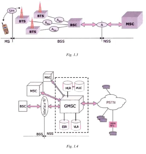
1.4 ARCHITECTURE OF A GSM NETWORK
A GSM network consists of several functional units that can be grouped into four main subsystems (see the horizontal description of the figs.1.3 and 1.4):
• the Mobile Station MS is the mobile terminal used by the subscriber
• the Base Station Subsystem BSS controls the radio link with the
Mobile Station
• the Network SubSystem NSS, the main part of which is the Mobile
services Switching Center (MSC), implements the connection
between the user of the mobile phone network and the users of the other, mobile and fixed networks
• the Operation and Support Subsystem OSS will oversee the proper
operation and setup of the network.
[image:12.595.66.535.274.770.2]Fig. 1.3
The communication between the different units of a GSM network is ensured by specific interfaces.
The possibility of roaming, that is of moving freely on the territory
served by one’s own administrator and also on that covered by other administrators of the countries adhering to the GSM, requires to store the users’ position in a data base and to refresh it as users shift.
At this pur pose the geographical service zone of the GSM network is divided hierarchically into differente Network service areas.
Then a GSM operator is always able to know the position of each subscriber.
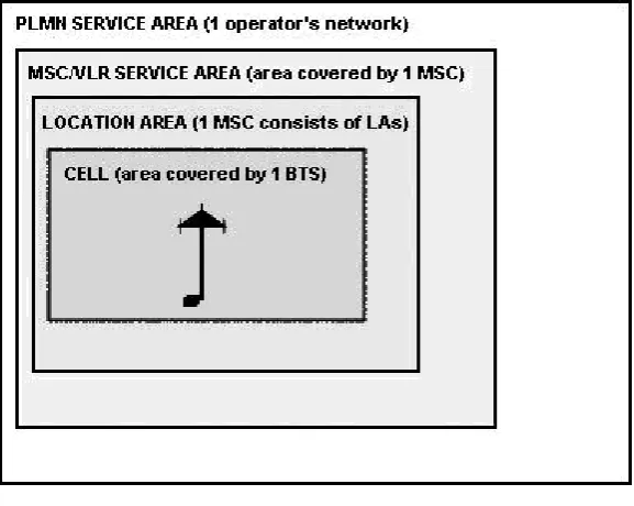
The Fig.1.5 shows the Architecture and interfaces of a GSM network and of other communication platforms.
1.5 NETWORK SERVICE AREAS
[image:14.595.215.504.140.370.2]Observe the composition of NETWORK SERVICE AREAS in the varios geographic zones.
Fig. 1.6
1.5.1 GSM Service Area
This service area consists of the separate networks of all the operators of the different countries sharing the GSM system with world extent.
1.5.2 PLMN Service Area
This is the whole covering area served by the Public Land Mobile Network(PLMN) of an individual operator.
A country can include different operators and consequently several PLMN.
Every PLMN is univocally identified by:
• Mobile Country Code(MCC): country code, and by
• Mobile Network Code(MNC): mobile operator code.
1.5.3 MSC/VLR Service Area
This is the area covered by only one MSC and by the VLR included in it.
MSC and VLR can be separated; therefore two separate areas: a MSC Service Area and a VLR Service Area, can be defined.
Fig. 1.7
1.5.4 Location Area
An MSC/VLR area is subdivided into more Location Areas (LAs).
A Location Area (the Fig. 1.8 shows six LAs) is defined as that area within which an MS can move freely without its position, stored in the VLR, must be refreshed.
The paging messages addressed to a MS, to inform of the arrival of a call, are radiated only in the LA where the MS is located correctly. When an MS passes from an LA to another LA, it will send a message of Location updating to the network, so that this can refresh the
information stored in the VLR (and, if necessary, in the HLR if also the VLR changes).
Every LA is identified by a Local Area Identity (LAI) having the following configuration:
LAI = MCC / MNC / LAC
where:
• MCC and MNC have the meanings explained above,
• LAC (Local Area Code): it univocally identifies an LA within the
PLMN of the operator.
1.5.5. Cell
This is the area covered by an individual BTS.
More cells geograohically adjacent are grouped into an LA.
Each cell is identified by a unique Cell Global Identity (CGI) having
the following structure:
CGI = MCC / MNC / LAC / CI
where:
• MCC, MNC and LAC have the meanings explained above, • CI (Cell Identity) univocally identifies a cell within an LA.
1.6 TECHNIQUES OF MULTIPLE ACCESS
When some resources must be shared by more users, some techniques of multiple access (or multiplexing) must be applied.
In detail, the same resource (repeater ot BTS) must be shared by more users, in cellular networks: so some specific techniques of access to this resource must be used.
The systems using radio frequency as communication means, show two resources: Frequency and Time.
During the frequency division each terminal uses a part of the
frequency spectrum for all the time: this technique is called Frequency Division Multiple Access (FDMA).
During the time division each terminal uses the whole (or most)
frequency spectrum for a part of the time: this technique is defined as Time Division Multiple Access (TDMA).
The third solution is the Code Division Multiple Access (CDMA)
where each terminal uses the whole frequency spectrum for all the time: CDMA uses some codes to identify the links.
1.7 TRANSPORT TECHNOLOGIES
This section will descrive the modernest transport technologies of wireless cellular systems, up to the last generation called 3G (3rd Generation).
1.7.1 1G
This is the first generation of cellular telephony.
The technique FDMA for the channel division (one per user) and the frequency modulation (FM) were used.
There were different standards:
NMT (Nordic Mobile Telephone)
AMPS (Advanced Mobile Phone System), used in USA
TACS (Total Access Communications System) and E-TACS (extended
version with higher number of channels) used in Europa and supplanted by GSM networks (2G)
C-450
Radiocom2000
RTMI (Radio Telefono Mobile Integrato = integrated mobile phone system, early system used in Italy),
and others more.
1.7.2 2G
The main difference is that 2G is digital, whereas 1G is analog. It is divided into TDMA and CDMA.
TDMA (Time Division Multiple Access), used for:
• Voice and data, up to 9.6 kbps
Pros and cons:
• low consumption of the battery • unidirectional transmission
• data rate decidedly slower than that of 3G.
As already mentioned, this technique enables a transmission medium (radio, in this case) shared by more users to enter the channel.
In detail, more users share the same channel (and frequency). The signal to be sent is divided into different Time Slots.
Each Time Slot is assigned to a different user.
Fig. 1.10
TDMA is a type of Time-division multiplexing with a slight difference: instead of having a unique transmitter and a unique receiver, there are more transmitters connected with a unique receiver.
The situation is complex in the Up-Link (connection from the Terminal to the Base station) because the Terminal can move and then it can modify the timing provoking some holes in transmission.
This technique has been standardized for different systems.
• GSM (Global System for Mobile Communications) is the system
using the bands of 900 MHz and 1.8 GHz, in Europe, and the band 1.9 GHz PCS, in USA.
GSM is used very much all over the world, its roaming is operating in over 180 countries and the Short Messaging Service (GSM-SMS) transmits in only one direction and it can send messages with a length up to 60 characters.
• D-AMPS (Digital AMPS) or IS-54/IS-136 established itself in North
America, ma it has been supplanted by GSM/GPRS and CDMA2000.
It was developed to use the AMPS channels (spaced of 30 kHz) and to allow a soft transition from the analog network to the digital network.
Three Time Slots per channel were used.
• PDC (Personal Digital Cellular) established itself in Japan.
• iDEN (Integrated Dispatch Enhanced Network) was developed
especially to increase the spectrum occupation with respect to 1G systems.
It works on a channelling of 25 kHz although it occupied only 20 kHz to provide a protection against interferences.
• DECT (Digital Enhanced Cordless Telecommunications) was
developed as a mobile system of private or business use.
At present it is widespread all over the world and it uses the band of 1900 MHz.
Normally it interact with a base station or gateway connected with the PSTN network.
Even more mobile terminals can be connected with a base station within a range of 100 m.
It uses a channelling of 1.728 MHz, twelve Time Slots and 32 kbit/s.
CDMA (Code Division Multiple Access)
This tecnnology is less widespread than TDMA, but at present its spreading is continuous and fast because it enables a higher transmission capacity.
If compared with the other technologies, CDMA offers the best combination of good siognal quality, high safety, low power consumption and excellent reliability.
Moreover it allows that the same frequencies can be shared by several terminals.
If compared with TDMA, it offers the advantage of enabling several terminals to be served by a lower number of cells.
It uses the Spread-Spectrum technology and a special coding diagram for assigning a different code to each transmitter.
This type of technology must use a band higher that that of the data item having to be sent.
cdmaOne is based on CDMA technology and it is used in Americas and
in some parts of Asia.
1.7.3 2.5G
It is an intermediate step between 2G and 3G.
It includes those technologies that have implemented the packet switching: it is not a standard, but a commercial definition.
Actually it works on GSM and CDMA networks.
GPRS (General Packet Radio Service), used for:
• Data, up to 115 kbps, it supports the data transmission by packets
Pros and cons:
1.7.3 3G
3G technologies are based on the specifications ITM-2000 issued by ITU: in the begining 3G was conceived as a univocal standard unified at world level; actually it has been implemented into four different standards.
EDGE (Enhanced Data GSM Environment), used for:
• Data, up to 384 kbps
This temporary solution is adopted by the operators that cannot supply W-CDMA technology (because they have not any licence), but they are provided with a GSM network
W-CDMA (Wideband CDMA).
It is commonly known as Universal Mobile Telecommunications System (UMTS).
This is the prevailing standard in the countries where the GSM is used and it is suitable for data transmission in circuit switched and packet switched Public Data Networks.
It is used for Voice and Data with rate from 144 kbps (rural environments and maximum mobility) and 384 kbps (sub-urban areas and low mobility) up to 2 Mbps (zones well covered and very low mobility). It will be developed up to 10 Mbps.
Pros and cons:
• This will be the prevailing technology, very good to ensure a global roaming
• First of all it has been implemented in the region of Pacific Asia
CDMA 2000
It represents an evolution of the CDMA standard developed in 2G environment.
It is particularly widespread in America, Japan and Korea.
It is used for:
• Voice and Data, from 144 kbps to 3 Mbps
Who proposed it promises a simpler migration from TDMA towards CDMA2000 than to W-CDMA, as well as a more efficient use of spectrum.
It has evolved to:
• CDMA2000 1xRTT: first phase of CDMA2000.
• CDMA2000 1xEV-DO: it sends data onto separate channels
2. COMPONENTS OF A CELLULAR NETWORK
2.1 MOBILE STATION (MS)
The mobile station (MS) represents the mobile unit enabling the user to enjoy the services offered by GSM.
It mainly consists of two components:
• Mobile Equipment (ME), that is the hardware equipment or
terminal supplying all the possible services of the Mobile Station. It is identified uniquely by the International Mobile Equipment Identity (IMEI)
• Subscriber Identity Module (SIM): this system of personalization
of the Mobile Station storse the specific parameters of the user (such as phone numbers, contacts, etc …).
Note that there is a clear distinction between the actual mobile equipment and the SIM that stores all the data identifying the subscriber.
This last componenti s separate from the terminal and it is removable. The components of a Mobile Station are often concentrated in the only
Mobile Equipment (ME) and SIM.
2.1.1 SIM Card
A SIM card includes a serial store where several pieces of information are saved, and of a processor being able to execute some Encryption algorithms.
The opportunities offered by these smart-cards can vary considerably between two different operators, according to the specific implementations.
Fig. 2.1
The main data stored in a SIM are:
• IMSI (International Mobile Subscriber Identity): this is a code for
identifying the user
• Ki (Individual subscribers authentication key): this is a secret
authentication key
• A3, that is an authentication algorithm, and
• A8 (Ciphering key generating algorithm, Encryption algorithm), that
is an encryption algorithm.
These last two algorithms can be assembled into a unique algorithm of
Moreover it must also store the following (compulsory) data: • IC card identification: serial code for identifying the SIM
• SIM service table: it indicates the optional services available in the SIM
• Location information: Temporary Mobile Subscriber Identity (TMSI), Location Area Information (LAI), current values of the Periodic Location Updating Timer (T3212) and of the Location update status;
• Cipher key (Kc) and cipher key sequence number
• BCCH information: list of the carriers that can be used for cell-reselection
• Access control class
• Forbidden PLMNs: forbidden networks
• HPLMN search period: timer of search of one’s own network when roaming
• Language preference • Phase of the SIM
• Personal Identity Number (PIN) • Indicator of PIN enabled/disabled • Counter of PIN typing errors • PIN Unblocking Key (PUK) • Counter of PUK typing errors
It can also store the following optional data:
• PLMN selector: automatic selection of network operator • List of the selected Cell Broadcast channels
• Abbreviated Dialling Numbers: list of short numbers
• Fixed Dialling Numbers: list of the only numbers that can be dialled • MSISDN number of the subscriber
• Last numbers dialled: list of the last numbers dialled • Short messages: list of SMS messages received and sent • Subscriber’s phonebook
• Counters for the service of Advice of Charge • Personal Identity Number 2 (PIN2)
• Counter of PIN2 typing errors • PIN Unblocking Key 2 (PUK2) • Counter of PUK2 typing errors
The enabling access to the service is supplied by the SIM card that is enabled by a Personal Identity Number (PIN) of four or eight digits (to
avoid any unauthorized use).
But, if the PIN code is typed erroneously for three times in sequence, the card is blocked to ensure an even higher security.
In this case, typing the 8-digit PUK code (PIN Unblocking Key) will
unblock the card.
As some new services have been added in the PHASE 2 of development of the GSM system, another PIN (PIN2) has been programmed to protect the content of some new fields and to differentiate the access. For instance, a subscriber can lend his/her own SIM card to a friend revealing the only PIN.
Thus he/she will be sure that this friend can only call without using all the services that require the PIN2.
Of course there is also a PUK2 with the same functions of PUK.
A SIM can store:
• 100 phone numbers and each phone number can be described with 12 alphanumeric characters
• 10 SMS messages (these quantities can vary according to the specific implementations of manufacturers), and
• a list of the subscriber’s favourite GSM operators: every time the signal of the network where he/she is recorded is missing, the GSM system will automatically apply for the access to the first one of the networks indicated in this list. If this application is rejected, the same operation is repeated with the next network, and so on. This procedure will continue cyclically until the subscriber is recorded on a new network.
The IMSI code and the authentication key Ki are the credentials for the identification of the subscriber: they are equivalent to the Equipment Serial Number(ESN) of analog systems.
The ESN code is a number of 11 digitts: the first three digits identify the manufacturer, then two digits are kept for a reserved (they are often set to zero), the other six digits are a serial number that identifies the terminal.
Then the IMSI code is associated with the GSM subscriber, whereas it does not concern the used Mobile Equipment (ME) at all.
The IMSI code has a maximum length of 18 digits and it is configured as indicated here below:
MCC
(3 digits)
MNC
(2 digits)
MSIN
(max 13 digits)
where:
• MCC: Mobile Country Code, identifying the operator’s country
• MNC: Mobile Network Code, identifyng the operatore inside the
country
• MSIN: Mobile Station Identification Number (max 13 digits), serial
2.1.2 SIM card of Phase II
A SIM card is available in two sizes: • ISO (or ID-1): size of a credit card
• Plug-in: size of a stamp, with dimensions of 25 x 15 mm, introduced
by Nokia and Ericsson.
The Read Only Memory (ROM) stores the operating system, the
administrator (that manages the Phase II GSM services) and the security algorithms A3 and A8.
The Random Access Memory (RAM) is used to execute the algorithms
and as buffer for data transmission.
The Electrically Erasable Programmable Read Only Memory (EEPROM) storse all the data of the subscriber.
The SIM cards of Phase II have a larger store enabling a higher storing capacity.
A serious trouble for all the SIM cards is represented by the deterioration suffered by EEPROMs in the writing/reading phases: this will reduce their duration (the correct operation of a GSM SIM card is usually guaranteed for approximately two years).
In fact the memory cells included in a normal EEPROM available on the market at present can support 10,000 write/read cycles at the most. Some SIM cards with a threshold of 100,000 cycles have been developed for particular applications.
2.1.3 Electrical characteristics
SIM card and ME are interfaced through eight pins: C1 to C8.
Their position on the SIM card and their dimensions are specified in ETSI 11.11.
Fig. 2.2
• C1: supply voltage Vcc (pin C1) of a SIM Card; it can be equal to 5
V, 3.3 V, or to 1.8 V • C2: RESET pin
• C3: the RESET signal is sent by the ME onto the pin C3 of the SIM,
it can range from 1 to 5 MHz. The SIM card has not any internal clock signal
• C4: at present it is not used in the GSM standard; it is kept free for
future developments
• C6: input pin of the programming voltage Vpp. As the SIM card
cannot directly be reprogrammed by the terminal in the GSM system, this pin C6 can (or cannot) be connected with Vcc, it can never be connected with the ground
• C7: for data input or output
• C8: at present it is not used in the GSM standard; it is kept free for
future developments
2.1.4 SIM locking
The SIM locking is a function supported by a lot of telephones.
It enables an operator to forbid the use of the telephone to all the SIM cards of other operators.
Thus an operator is sure that the new user remains its own subscriber for a certain period.
At the same time the user has often the opportunity of buying a telephone at a cheaper price.
Some operators supply a code number for unlocking the telephone, after a certain time (one or two years).
This code number is different for the telephones and it is calculated according to the IMEI.
The SIM locking is forbidden in a lot of countries such as Denmark, for instance.
2.1.5 Mobile Equipment (ME)
IMEI (International Mobile Equipment Identity) and IMEISV
(International Mobile Equipment Identity Software Version) codes identify a Mobile Equipment uniquely.
They can be distinguished by the number of their digits: 15 or 16.
They are safely stored in the mobile phone directly by the manufacturer. If compared with the normal IMEI, the IMEISV also includes the information concerning the software version installed in the GSM terminal.
The IMEI code has the following configuration:
TAC
(6 digits) (2 digits) FAC
SNR
(6 digits)
SP
(1 digit)
The IMEISV code has the following configuration:
TAC
(6 digits) (2 digits) FAC
SNR
(6 digits)
SVN
(2 digits)
where:
• TAC: Type Approval Code, it is supplied by a Central Authority of
GSM and it identifies the basic model of the equipment
• FAC: Final Assembly Code, it identifies the place of production or
• SNR: Serial Number
• Sp: additional riserve digit
• SVR: Software Version Number
GSM terminals are divided into five classes according to the maximum power of transmission on radio channels.
They can also vary their output power dynamically on 15 levels (Dynamic Power Control) to keep a very good transmission quality by limiting co-channel interferences and consumptions at the most.
Terminals have been classified according to their output peak power as indicated here below:
• Class 1: 20 W • Class 2: 8 W • Class 3: 5 W • Class 4: 2 W • Class 5: 0.8 W.
The radio transmission and reception actually occur in different times (rated delay of 3 time slots).
This eliminates the use of the duplexer filter that is absolutely necessary in analog systems to separate the transmission and reception signals being active continuously and at the same time.
The main function that must be carried out by a mobile phone are: • radio transmission and reception
• selection of the best serving cell with respect to the speech quality • recording the the location area
• transmission measures on the used radio channel and on the sideband channels
• transmission power control • handover
• declaration of its own IMEI
• man-machine interface (display and keypad) • authentication and encryption of speeches
2.2 BASE STATION SUBSYSTEM (BSS)
The Base Station Subsystem (BSS) represents the radio section of the
system and consequently it includes the functional units that enable to ensure the radio covering of an area consisting of one or more cells. It includes two units:
• Base Transceiver Station (BTS), and
• Base Station Controller (BSC).
The communication interface between these two units, named A-bis, is
standardized.
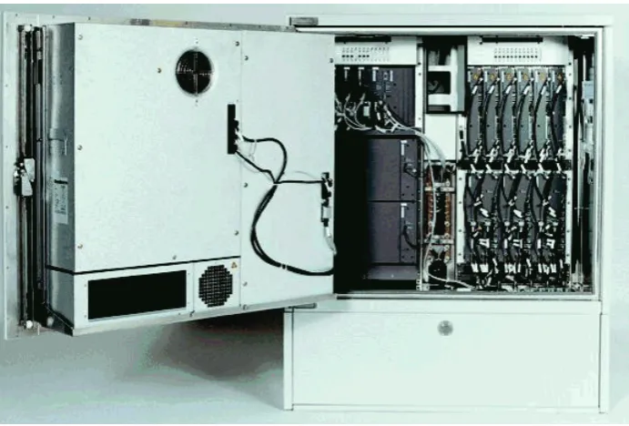
2.2.1 Base Transceiver Station (BTS)
The acronym BTS indicates the functional unit consisting of the transceivers and of the equipment enabling to supply a cell with radio covering.
Usually BTS are also called Base Radio Stations (BRS). The fig. 2.3 shows an example of radiating panel.
Fig. 2.3
This panel has the following electrical characteristics:
• Frequency Range: 870 - 960 MHz
• Gain: 16 dBi
• Polarization: +45 º and -45 º • Beamwidth: 85 º (H) / 9 º (V) • Lateral side lobes: > 19 dB
• Front /Back ratio: > 25 dB
• Power: 500 W (50 Ω - 7/16 female)
Fig. 2.4
2.2.2 Base Station Controller (BSC)
The base station controller (BSC) oversees the operation of one ore more BTS, manages the selection of radio channels (setup and release of links), the frequency-hopping, the internals handover, and others. It ensures the connection between a mobile station (MS) and the Mobile services Switching Center (MSC).
A wide urban area includes a high number of BTS controlled by one or few BSC.
When these two units are not in the same place, the BTS-BSC link is ensured by a PCM specific line of 2.048 Mbit/s that supplies 32 channels at 64 kbps.
As the vocal coding used by GSM is different from that PCM, a special device, called TRAU (Transcoder Rate Adapter Unit) is necessary: this
device will carry out a matching or transcoding from the GSM coding (13 kbps; 16 kbps including the redundancy for the line coding) into PCM coding (64 kbps).
This transcoding can be carried out:
• in the BSC (TRAU installed in BSC) so that four multiplexed GSM traffic channels can be inserted into a PCM channel; thus the BTS-BSC link can be used at the best (remote transcoding), or
• in the BTS (TRAU installed in BTS); this transcoding is convenient only in the case of a common location of BTS and BSC (local transcoding).
The PCM frame has a duration of 0.125 ms.
It is subdivided into 32 channels of 64 kbps (TS equal to 0.125/8 = 3.9
Therefore the total capacity of a channel is: 64x32=2.048 Mbit/s.
TS 0 corresponds to the synchronism, TS 16 to signalling, the remaining 30 ones are reserved to the traffic channels.
A signalling channel is necessary for each radio carrier (TRXC), that is 8 TCH channels.
Now analyze the performance in both the cases (table 2.1).
• Local transcoding: the PCM channel carries up to three radio carriers (TRXC), that is 24 TCH channels, using (8+1)x3=27 TS
• Remote transcoding: the PCM channel carries up to ten radio carriers (TRXC), that is 80 TCH channels, using (2+1)x10=30 TS (in this case, a TRXC carrier requires two TS for the TCH channels, and 1 for signalling).
LOCAL transcoding TS REMOTE transcoding
Synchronism 0 Synchronism
TRXC 1
Signalling TRXC 1 1 Signalling TRXC 1
TRXC 1
Traffic channels 1-8 TRXC 1
2 Traffic channels 1-8 TRXC 1 3
4 Signalling TRXC 2
TRXC 2 5 Traffic channels 1-8
TRXC 2 6
7 Signalling TRXC 3
TRXC 3 8 Traffic channels 1-8
TRXC 3 9
TRXC 2
Signalling TRXC 2 10 Signalling TRXC 4
TRXC 4
Traffic channels 1-5 TRXC 2
11 Traffic channels 1-8 TRXC 4 12
13 Signalling TRXC 5
TRXC 5 14 Traffic channels 1-8
TRXC 5 15
Signalling 16 Signalling
TRXC 2 Traffic channels 6-8 TRXC 2
17 Signalling TRXC 6
TRXC 6 18 Traffic channels 1-8
TRXC 6 19
TRXC 3
Signalling TRXC 3 20 Signalling TRXC 7
TRXC 7
Traffic channels 1-8 TRXC 3
21 Traffic channels 1-8 TRXC 7 22
23 Signalling TRXC 8
TRXC 8 24 Traffic channels 1-8
TRXC 8 25
26 Signalling TRXC 9
TRXC 9 27 Traffic channels 1-8
TRXC 9 28
Not used
29 Signalling TRXC 10
TRXC 10 30 Traffic channels 1-8
TRXC 10 31
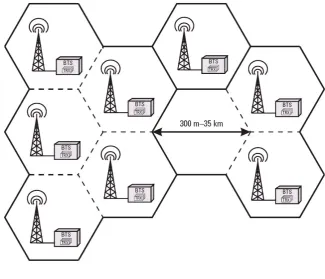
2.2.3 Cell topology
Cells and their base transceiver stations (BTS) can take three
configurations according to the network load, to the suscribers’ uses and to the morphology, to ensure the best radio coverage onto the area.
StandardConfiguration, where:
• every BTS has assigned a different Cell Identity (CI)
• a certain number of BTS (often only one) form a Location Area (LA). The fig. 2.5 shows three Las respectively consisting of one,
three and five BTS.
This is one of the most frequent configurations.
[image:31.595.190.516.283.562.2]The configurations described in the next page are suitable for urban areas with rising traffic density.
Fig. 2.5
The Umbrella CellConfiguration includes (fig. 2.6):
• a BTS of high power with an antenna installed in a very high position that provides an “umbrella-shaped” coverage for a number of BTS characterized by low power and small diameters of the covering area; • the frequencies used by the umbrella cell cannot be used by any
internal cell to avoid any interference.
Fig. 2.6
The configuration with Sectorized (Collocated) BTS includes (fig.
2.7):
• several BTS arranged in a place with the antennas covering only an area of 120° or 180° and using typically transmitters of low power; • the different BTS can easily be synchronized (differently from the
case of Umbrella Cell configuration);
• all the BTS can be connected with the BSC in an economical way via the interface A-bis
This configuration, as well as the Umbrella Cell configuration, are typically used in the areas with high density of population.
2.3 NETWORK SUB-SYSTEM (NSS)
The network subsystem, often identified as Intelligent Network (IN),
supplies a lot of services.
The mobile phone system GSM is a public telecommunications network, consequently it must include some telephone exchanges that can route the calls.
Then the central component is the Mobile services Switching Center (MSC).
An MSC will cover a certain area of the territory (consequently it controls all the BSC of that zone) and it must serve all the MS moving in that area.
It can manage the users’ mobility by exchanging information continuously with a data base, called Visitor Location Register (VLR),
that store the information concerning the MS available in that area (user identity, IMEI, phone number, MSISDN, authentication parameters, etc…) temporarily.
These MS are merely "visitors" in the area served by the VLR. In fact, they can move to an area served by another VLR in any time. Although the VLR can be implemented as functional unit, separately from the MSC, all the manufacturers prefer to assemble them together (the interface between these two elements can be proprietary) and the resulting assembly is usually defined MSC/VLR.
In this case both the units will cover the same geographic area, called MSC/VLR area.
Every administrator has its own central data base, named Home Location Register (HLR), where both the subscribers’ data (known as
static) and other (dynamic) data that can vary for actions of the same users (activation of additional services, etc…), as well as the identity of the VLR where the user’s MS is recorded as "visitor", are stored permanently.
As the HLR is merely a data base, it only storse the safety parameters, without generating them.
These parameters are calculated with proper algorithms by a functional unit named Authentication Center (AuC).
The problem of the possible use of stolen, faulty or not approved mobile equipment ME can find a solution in the use of a functional unit, the Equipment Identity Register (EIR), that stores all the IMEI codes
signalled as faulty or stolen.
2.3.1 Mobile Services Switching Center (MSC)
The most important component of a network subsystem is the Mobile services Switching Center (MSC).
It carries out the functions of a normal network switching node, that is: • setting up (including authentication)
• checking and • taxing
the calls from/to the MS present in the geographic area served by it.
Moreover it performs all the essential operations to manage a mobile user such as the mobility management and call routing.
These functions are carried out in collaboration with the other units of the network subsystem.
The MSC supplies the links with the following fixed networks:
• Public Switching Telephone Network (PSTN) • Integrated Services Digital Network (ISDN)
• Packet Switched Public Data Network (PSPDN) or Circuit Switched Public Data Network (CSPDN).
2.3.2 Gateway Mobile Switching Center (GMSC)
All the calls coming from fixed networks or from mobile networks of other administrators and sent to a GSM network, are forwarded to a special MSC, called Gateway MSC (GMSC): this is the access point to the GSM PLMN (Public Land Mobile Network) where the called mobile user is recorded.
The GMSC interrogates the subscriber’s HLR that questions the proper VLR, in its turn; then it will route the call to the MSC controlling the zone where the subscriber meets.
2.3.3 Home Location Register (HLR)
The HLR is the data base where an administrator of GSM network stores the data concerning its own subscribers permanently.
Every administrative action affecting the user data is carried out by the network administrator on the HLR.
It can be unique, or stand-alone, for the whole network, or it can be distributed in the system: then some MSC cannot have any HLR, but they can be connected with that of other MSC.
An AuC for generating the safety parameters can be associated with a HLR.
A HLR number is assigned to each HLR; this number is supplied to the concerned VLRs and it enables to identify the HLR corresponding to every MS recorded in them.
But, as a GSM network is interconnected with other networks (PSTN, ISDN, other PLMN), a numbering plan consistent with these networks must be programmed.
A phone number (MSISDN) is assigned to every MS: this number
uniquely identifies a subscriber in the numbering plan of the international public switching telephone network, according to the specifications E.164 on the numbering for ISDN (natural replacements of the traditional PSTN).
An MSISDN has a maximum length of 15 digits with the following configuration:
CC NDC IN
where:
• CC: Country Code, international code number complying with the
specifications E.163
• NDC: National Destination Code; it identifies a GSM PLMN at
national level. Several NDC can be located in a PLMN
• SN: Subscriber Number, that identifies the subscriber in the PLMN
of his/her own operator.
The CC and NDC codes enable to identify the GSM operator, whereas the first digits of SN enable to go back to the HLR where the called MS is recorded.
The main user data stored in a HLR are:
• International Mobile Subscriber Identity (IMSI), that identifies
the subscriber uniquely inside any GSM network; it is also included in the SIM card
• Mobile Station ISDN Number (MSISDN), that identifies a
subscriber uniquely in the numbering plan of the international public switching telephone network. public switching telephone network. There may be several numbers according to the subscribed services (for instance, voice, data, fax can be identified by separate numbers) • Type and state of the additional services and of the services available
for the subscriber (voice, data, SMS)
• VLR number, for knowing the VLR where the MS is currently
recorded.
The main functions of a HLR can be summarized as follows: • security: dialogue with AuC and VLR
• location management: dialogue with VLR
• routing information (MSRN): dialogue with GSMC • managing the user data and the costs of calls
2.3.4 Visitor Location Register (VLR)
This register (VLR) storse and refreshes the information concerning the MS that move temporarily within the area covered by it.
Thse data selected by the HLR are necessary for the check of calls and the control of additional services.
On the whole the geographic territori covered by a GSM network can be divided into several service areas: each are is controlled by a MSC and is provided with a VLR.
When a MS enters the area covered by a new MSC, it is stored in the register of the visitors (VLR) of that MSC; at the same time the general register od users (HLR) is updated to record the new geographic position of the terminal.
The main user data stored in the VLR are:
• IMSI, MSISDN, MSRN and safety parameters • HLR number: for identifying its own HLR
• Temporary Mobile Subscriber Identity (TMSI): used to censure the safety of IMSI. It is assigned every time the Location Area (LA) varies
• State of the MS (off, not reachable, etc…), category (operator, ordinary user, test call) and possible priority
• State of the additional services (Call Waiting, Call Divert, Call Barring, etc…)
• Types and state of the services available for the subscriber (voice, data, fax, SMS, etc…), called bearer services and teleservices
• Location Area Identity (LAI) of the area where the MS meets within those controlled by the MSC/VLR.
2.3.5 Authentication Center (AuC)
AuC is the functional unit of the GSM system charged with the generation of the necessary parameters for the authentication of users. It will check whether the service has been requested by a rightful subscriber, supplying both the codes for authentication and encryption, to guarantee the subscriber and the network operator from undesired infringements of any third party.
The authentication verifies the rightfulness of the SIM without transmitting any personal data of the subscriber such as IMSI and cipher key, on the radio channel, to check whether the subscriber who is trying to enter is the true one and not a clone.
On the contrary, the encryption generates some secret codes that will be used to encrypt all the communication exchanged on the radio channel.
AuC will store: • the IMSI code
that are used to authenticate and encode the radio channels, besides a generator of random numbers (RAND), the algorithms A3 and A8.
Authentication is always carried out every time a MS is connected with the network: when it receives or sends a call, at the expiry of the periodical location updates, at the request of enabling, disabling or questioning the additional services.
As the data handled by AuC are extremely important for the network and for the user, special safety and protection measures are normally taken for their preservation.
2.3.6 Equipment Identity Register (EIR)
Every mobile equipment (ME) is uniquely indentified by the IMEI code, in the GSM system.
The IMEI does not concern the subscriber’s identity (IMSI stored in the SIM card).
EIR is a data base storing the IMEI codes.
An IMEI can be invalidated when the mobile equipment is stolen or when it is not approved.
A correct operation of EIR requires the definition of various "lists" such as:
• White list: it includes the IMEI of all the ME of approved type and
operating, available in the countries adhering to GSM. Threfore they are authorised to be connected with the network
• Black list: it includes all the IMEI that are locked (for instance, those
stolen or of not approved type); therefore they are not authorized to be connected with the network
• Grey list: it includes all the IMEI marked as faulty, or those of
equipment not approved (at the administrator’s discretion). The terminals inserted in this list are signalled to the system operators with an alarm signal when they request the access, so that the subscriber using the equipment and the area from where he/she calls, can be identified.
Every time a terminal tries to connect with the network, the MSC checks with the EIR whether the ME is not included in the Black list or in the Grey list: in this case, the access to the network is forbidden. The EIR can be unique for all the system, or it can be implemented in a distributed configuration.
Generally it is better to keep it physically separated from the other units (HLR, AuC, etc…) for safety reasons.
This is also accessibile in remote way to enable the updating of its various lists from any point of the network.
2.4 OPERATION AND SUPPORT SUBSYSTEM (OSS)
A GSM network consists of a lot of functional units of different type that need proper activities of Operation, Administration and Maintenance: all these operations must properly be coordinated to avoid any discrepancy among the network parameters.
2.4.1 Operation and Maintenance Center (OMC)
An OMC is the functional unit that enables the GSM operator to monitor and check the correct operation of a part of the GSM network consisting of one or more MSC, with the corresponding BSC and BTS.
An OMC has the following functions:
• managing the configurations and performance of all the elements of the GSM network (BSC, BTS, MSC, VLR, HLR, EIR and AUC) • managing the faults, alarms and the state of the system with the
possibility of carrying out various types of tests to analyze the performance and to verify the correct operation of the system itself • controlling the safety
• gathering all the data concerning the subscribers’ traffic that are necessary for the invoicing.
2.4.2 Network Management Center (NMC)
2.5 GSM INTERFACES
GSM recommendations have defined various interfaces to enable the communication among the different system units.
Different protocols or specific parts of general protocols correspond to these interfaces.
This section will summarize their main characteristics.
• Um: this air-interface is used to carry the comnunication between MS and BTS
• A-bis: this is the internal interface of the BSS; it enables to
communicate between BTS and BSC. The interface A-bis enables the control and location of radio frequencies in BSTs
• A: the interface A is inserted between BSS and MSC; it manages the
location of radio resources in MS and their mobility
• B: the interface B is inserted between MSC and VLR and it uses the
protocol MAP/B. Generally the MSC alsi includes the VLR, so that this becomes an “internal” interface. When a MSC needs information on the position of a MS, it interrogates the VLR through the protocol MAP/B on the interface B
• C: the interface C is inserted between HLR and G-MSC or G-SMS.
Every call coming from outside the GSM netweork and sent to a MS (for instance, a call coming from the fixed network PSTN) must compulsorily be sent to the Gateway to get the routing information and complete the call; the protocol MAP/C on the interface C is just charged of this function. Moreover, the MSC can optionally transfer some pieces of information on the costs of the calls, to the HLR • D: the interface D is inserted between VLR e HLR; it uses the
protocol MAP/D to exchange information concerning the position or the management of a MS
• E: the interface E interconnects two MSC; it enables to exchange
data concerning the handovers between the anchor and the relay
MSC using the protocol MAP/E
• F: the interface F interconnects a MSC with the EIR; it uses the
protocol MAP/F to verify the state of the IMEI of a MS
• G: the interface G interconnects two VLR of two different MSC and
uses the protocol MAP/G to transfer the information of a MS, for instance, during the location update procedure
• H: the interface H is inserted between a MSC and the G-SMS; it
uses the protocol MAP/H to transfer the short text messages (SMS) • I: the interface I interconnects a MSC directly with a MS; the
3. AIR INTERFACE
3.1 NOISES AND INTERFERENCES
A radio channel of a mobile phone system can be deteriorated by two causes;
• noise and • interference.
The noise consists of environmental phenomena such as lightning, and of causes such as electric motors.
On the contrari, there are two types of interferences: • sideband splash
• co-channel interference.
A beam of electromagnetic waves can be reflected by obstacles met on its path.
In the case of a mobile phone network this phenomenon is defined as multiple path.
The propagation by multiple paths leads to the following advantages: • delayed diffusion of the received signal
• random phase changes that generate fast fading of the signal level (Rayleigh fading)
• randon frequency modulation due to different shuifts (Doppler effect) on different paths
3.1.1 Co-channel interference
If the distance between two transmitters that work on the same frequencies is not long enough, the signals of two or more cells can arrive at a MS, on the same channel, thus provoking a phenomenon called co-channel interference.
Therefore the capacity of a mobile phone netowrk is limited by the reuse capacity of frequencies.
3.1.2 Sideband splash
This type of interference is due to the fact that the filters used in the equipment to eliminate the signals and noises falling outside the band, are not ideal.
Both the expected frequency and the sideband frequencies arrive at the receiver after crossing the filter.
3.1.3 Doppler effect
The continuous movement of the Mobile Stations with respect to the BTS provokes a real shift of the reception frequency, in reception; this effect is commonly known as Doppler effect.
If a MS that is talking moves at a speed of 50 km/h, the average Doppler compensation is of approximately 30 Hz.
3.1.4 Fading
The propagation of electromagnetic waves does not occur in an ideal free space, consequently it is affected by different phenomena:
• reflection, against obstacles of bigger size than its wavelength
• refraction, in the passage from a transmission medium to another
one: for instance, air-cement, and • diffraction.
The phenomenon of reflection is particularly interesting because it can provole some sudden and instantaneous fading of the received signal.
There are different types of fading:
• slow fading, due to the presence of big obstacles (hills or tall
buildings) that create some shadow zones;
• fast fading, due to the presence of several reflecting surfaces that
send several signals of different phases to the receiving antenna. When these signals are in phase opposition provole a deep fading;
• Rice fading, when the antenna receives a direct signal (the
transmitting antenna is visible) and several reflected signals.
3.1.5 Diversity
The effects of fading can be reduced with two methods:
• Antenna diversity. Two receiving antennas, placed at a distance
equal to an odd multiple of a quarter of wavelength (the wavelength is of 30 cm at 900 MHz), are used. As the signals received by these two antennas cover different paths, it is less probabile that they both are affected by fading at the same time.
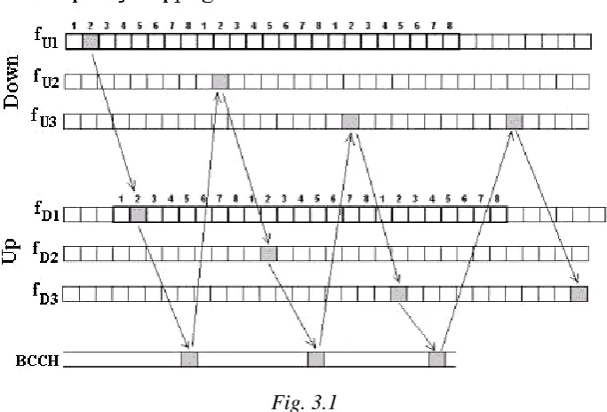
• Frequency diversity. The same signal is transmitted at different
frequencies: in fact, if a frequency is subject to fading, this is not possibile at another frequency because the fading mainly depends on the carrier frequency. Actually the same number of Time Slots is kept, but carriers will hop from a frame to another.
Fig. 3.1
This technique offers two adantages:
• reduction of Rayleigh fading; if a frequency undergoes this type of fading "hopping" in pseudo-random way on various frequencies, it is hard that they undergo the same fading. Thus the interferences due to this phenomenon are reduced;
• reduction of co-channel interferences; implementing the Frequency-Hopping in two MS placed in two near cells that use the same TS and travel on equal frequencies, will lead to a reduction of the interferences between the two MS.
The Frequency-Hopping algorithm is transmitted on the Broadcast Control Channel (BCCH).
This is the reason why the time slot 0 (carrying the channel BCCH) does not undergo any frequency-hopping.
3.2 FDMA/TDMA MULTIPLEXING
The GSM system uses a combination of frequency division (FDMA) and time division (TDMA) multiplexing techniques for the radio resource.
3.2.1 FDMA multiplexing and frequency reuse
The GSM system uses the technique of Frequency Division Multiple Access to divide the allowed bandwidth into carrier frequencies or channels.
A channel number, called ARFCN (Absolute Radio Frequency Channel
Number), is associated with each frequency for its univocal identification.
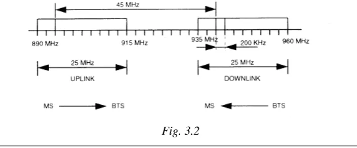
GSM 900 The International Telecommunication Union (ITU) has assigned the
GSM 900 system:
• the band 890-915 MHz for the communication between MS and BTS (Uplink)
• the band 935-960 MHz for the communication between BTS and MS (Downlink)
The band of 25 MHz is divided into 124 carriers, numbered from 1 to 124.
The spacing between carriers amounts to 200 kHz.
E-GSM 900 The E-GSM 900 (Extended GSM) system has been assigned:
• the band 880-915 MHz for the Uplink • the band 925-960 MHz for the Downlink
The channels with ARFCN from 0 to 124 are like those of the GSM band.
Then the channels with ARFCN from 975 to 1023 follow; their spacing is still 200 kHz.
GSM-R The GSM-R (GSM Railway) system, standardized for railway uses, has
been assigned:
• the band 876-880 MHz for the Uplink • the band 921-925 MHz for the Downlink
The band of 4 MHz is divided into 19 carriers, with ARCFN from 955 to 974.
The spacing between carriers amounts to 200 kHz.
[image:43.595.180.533.633.779.2]The fig. 3.2 shows the map of frequency-GSM channels for all the systems mentioned above.
DCS 1800 The DCS 1800 system has been assigned:
• the band 1710-1785 MHz for the Uplink • the band 1805-1880 MHz for the Downlink.
The band of 75 MHz is divided into 374 carriers, numbered from 512 to 885.
The spacing between carriers amounts to 200 kHz.
PCS 1900 The PCS 1900 system has been assigned:
• the band 1850-1909.6 MHz for the Uplink • the band 1930-1989.6 MHz for the Downlink.
The band of 60 MHz is divided into 299 carriers, numbered from 512 to 810.
The spacing between carriers amounts to 200 kHz.
GSM 400 The last standard in chronological order is GSM 400, that has been
subdivided into two further standards: the GSM 450 characterized by:
• the band 450.5-457.6 MHz for the Uplink • the band 460.4-467.6 MHz for the Downlink.
The band of 7 MHz is divided into 35 carriers, numbered from 259 to 293.
The spacing between carriers amounts to 200 kHz;
the GSM 480 characterized by:
• the band 478.8-486 MHz for the Uplink • the band 488.8-496 MHz for the Downlink.
The band of 7 MHz is divided into 35 carriers, numbered from 306 to 340.
The spacing between carriers amounts to 200 kHz.
GSM 850 Another standard defined is GSM 850 characterized by:
• the band 868-894 MHz for the Uplink • the band 824-849 MHz for the Downlink.
The band of 26 MHz is divided into 124 carriers, numbered from 128 to 251.
The spacing between carriers amounts to 200 kHz.
Carrier frequencies are distributed, in a country, among the various operators of GSM system and of any other analog system already existing.
The N channels (carrier frequencies) assigned to an operator are divided into M groups so that each group is supplied with N/M channels.
A group of channels is assigned to each cell, to diversify the frequencies used by cells being geographically adjacent.
A cluster is defined as the assembly of the adjacent M cells where all
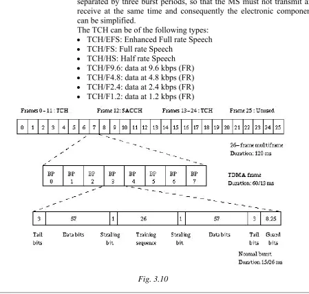
3.2.2 TDMA multiplexing
Each individual cell is divided into 8 time slots or bursts with duration
of 0.577 ms, according to the technique of Time Division Multiple Access (TDMA).
The set of 8 time slots, lasting 4.616 ms (0.577x8), is called frame.
The kth time slot of each frame of the ith carrier forms a channel; they are 992 (124x8) on the whole.
In its turn, the sequence of frames too is divided periodically among more channel, with a kind of second-level TDMA that assigns one or more frames to an individual channel.
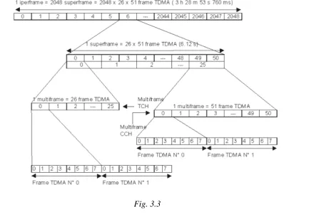
Then the traffic channels are organized in groups of 26 frames, the control channels in groups of 51 frames.
These groups form a multiframe.
The two multiframes with durattion of 120 ms and 235.4 ms are inserted into a superframe of 6.12 s that respectively includes 51 and 26
multiframes (for a total of 1326 frames), unifying the structure of the two channels.
In their turn 2048 superframes form a hyperframe consisting of
222=2715648 frames numbered progressively (frame number, FN) and
cyclically on a period of 3 hours, 28 min, 53 s and 773 ms.
[image:45.595.88.522.448.763.2]In conclusion a physical channel is identified by its own number of time slot (TS), of frame (FN) and of carrier frequency.
The uplink and downlink channels are separated by 3 time slots, to simplify the necessary electronic components of a MS so that transmission and reception cannot occur at the same time.
Thus a MS that is in reception in the time slot Tk of the carrier Fi MHz, will transmit in the time slot T(k+3) on the frequency Fi - 45 MHz. The remaining six time slots can be reserved to the listening of the other channels that the MS can receive, so that it can drive the handover procedures efficaciously.
The total number of the available physical channels is 992: they must be distributed inside the cluster of cells.
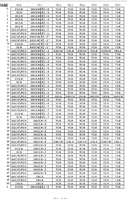
Logical channels must be inserted "physically" in the TDMA structure. A logical channel is associated with a time slot of a frequency on
which it alternates with the other channels in the sequence of frames. The time slot 0 of only one of the frequencies assigned to a cell in both directions is usually reserved to the signalling channels (BCCH, SCH, FCCH, AGCH, PCH, RACH, SDCCH).
This frequency takes the name of fundamental carrier or BCCH carrier, The FCCH, SCH and BCCH channels must always be transmitted in downlink to enables the Mobile Stations to connect with the network.
3.3 HANDOVER
One of the peculiar characteristics of cellular systems is the possibility of talking on the phone while going on moving freely in the territory. This mobility can lead to the necessity of changing serving cell or transmission channel frequently to ensure a good quality of the signal to the user permanently.
This automatic switching without any break of the link is called handover.
There are several types of handover:
• normal Handover; that occurring during a call
• SDCCH Handover, that occurring during the signalling of the call
setup. The SDCCH is the signalling channel of the Air interface where the signalling of call setup is sent
• Directed Retry; it occurs after the signalling of call setup has ended,
but the traffic channel has not been assigned yet. Actually, the signalling of call setup is carried out through a cell, whereas the call in progress (that is paid) comes from another cell
• Handover due to Traffic Reasons; this is ordered by the GSM
network to the MS to balance the load of cells.
In detail, the SDCCH handover, Directed Retry and Handover Due to Traffic Reasons are not used in the case of channel-channel intracell handover.
Moreover the Directed Retry is not applied to the intercell MSC-MSC handover.
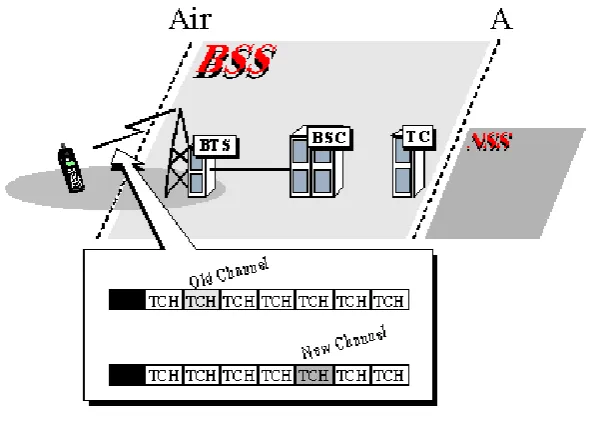
3.3.1 Intracell (Channel-Channel) Handover
[image:47.595.207.504.153.365.2]It enables to transfer a communication among different channels (or TDMA time slots) of the same cell, that is of the same BTS (Fig. 3.4).
Fig. 3.4
3.3.2 Intercell / Intra BSC / BTS – BTS Handover
It enables to transfer a communication among different cells controlled by the same BSC (Fig. 3.5).
3.3.3 Intercell / Inter BSC / BSC - BSC Handover
It enables to transfer a communication among cells of different BSCs controlled by the same MSC (Fig. 3.6).
Fig. 3.6
3.3.4 Intercell / Inter MSC / MSC - MSC Handover
It enables to transfer a communication among cells controlled by different MSCs (Fig. 3.7).